manuals.online logo
Brands
  1. Home
  2. •
  3. Brands
  4. •
  5. Leuze electronic
  6. •
  7. Relay
  8. •
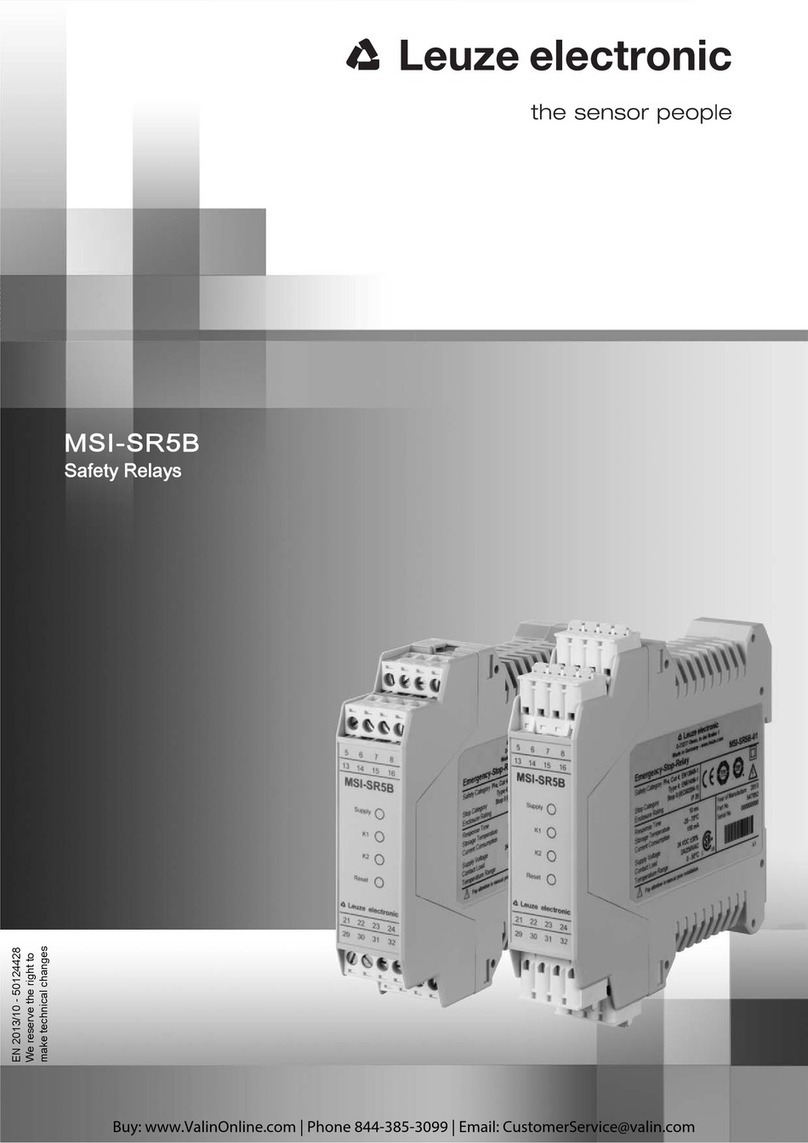
  9. Leuze electronic MSI-SR5B Series User manual

Leuze electronic MSI-SR5B Series User manual

SAFE IMPLEMENTATION AND OPERATION
Original operating instructions
EN 2013/10 - 50124428
We reserve the right to
make technical changes
Leuze electronic MSI-SR5B 2
© 2013
Leuze electronic GmbH + Co. KG
In der Braike 1
D-73277 Owen / Germany
Phone: +49 7021 573-0
Fax: +49 7021 573-199
http://www.leuze.com
[email protected]
Leuze electronic MSI-SR5B 3
1.1 Used symbols and signal words . . . . . . . . . . . . . . . . . . . . . . . . . . . . . . . . . . . . . . . . . . . . . . . . . . . . 5
1.2 Checklists . . . . . . . . . . . . . . . . . . . . . . . . . . . . . . . . . . . . . . . . . . . . . . . . . . . . . . . . . . . . . . . . . . . . . 5
2.1 Approved purpose and foreseeable improper operation . . . . . . . . . . . . . . . . . . . . . . . . . . . . . . . . . . 6
2.1.1 Proper use . . . . . . . . . . . . . . . . . . . . . . . . . . . . . . . . . . . . . . . . . . . . . . . . . . . . . . . . . . . . . . . . . . . . . 6
2.1.2 Using E-Stop buttons. . . . . . . . . . . . . . . . . . . . . . . . . . . . . . . . . . . . . . . . . . . . . . . . . . . . . . . . . . . . . 7
2.1.3 Using reset buttons . . . . . . . . . . . . . . . . . . . . . . . . . . . . . . . . . . . . . . . . . . . . . . . . . . . . . . . . . . . . . . 7
2.1.4 Foreseeable misuse . . . . . . . . . . . . . . . . . . . . . . . . . . . . . . . . . . . . . . . . . . . . . . . . . . . . . . . . . . . . . 7
2.2 Competent persons . . . . . . . . . . . . . . . . . . . . . . . . . . . . . . . . . . . . . . . . . . . . . . . . . . . . . . . . . . . . . . 8
2.3 Responsibility for safety. . . . . . . . . . . . . . . . . . . . . . . . . . . . . . . . . . . . . . . . . . . . . . . . . . . . . . . . . . . 8
2.4 Disclaimer . . . . . . . . . . . . . . . . . . . . . . . . . . . . . . . . . . . . . . . . . . . . . . . . . . . . . . . . . . . . . . . . . . . . . 8
9
3.1 System overview . . . . . . . . . . . . . . . . . . . . . . . . . . . . . . . . . . . . . . . . . . . . . . . . . . . . . . . . . . . . . . . 10
3.2 Display elements . . . . . . . . . . . . . . . . . . . . . . . . . . . . . . . . . . . . . . . . . . . . . . . . . . . . . . . . . . . . . . . 10
7.1 Terminal assignments . . . . . . . . . . . . . . . . . . . . . . . . . . . . . . . . . . . . . . . . . . . . . . . . . . . . . . . . . . . 17
7.2 Sensor wiring . . . . . . . . . . . . . . . . . . . . . . . . . . . . . . . . . . . . . . . . . . . . . . . . . . . . . . . . . . . . . . . . . . 17
7.2.1 Selecting the operating modes . . . . . . . . . . . . . . . . . . . . . . . . . . . . . . . . . . . . . . . . . . . . . . . . . . . . 18
7.2.2 Acceptance of pending sensor signals (S1 and S2), for both channel 1 (Sx1) and channel 2 (Sx2) .
19
7.2.3 Acceptance of the RES manual release signal via the start button at (RES-I) . . . . . . . . . . . . . . . . 19
7.3 Circuit diagram examples . . . . . . . . . . . . . . . . . . . . . . . . . . . . . . . . . . . . . . . . . . . . . . . . . . . . . . . . 19
7.4 Connecting to the machine control . . . . . . . . . . . . . . . . . . . . . . . . . . . . . . . . . . . . . . . . . . . . . . . . . 23
8.1 Switching on . . . . . . . . . . . . . . . . . . . . . . . . . . . . . . . . . . . . . . . . . . . . . . . . . . . . . . . . . . . . . . . . . . 24
8.2 Start/restart . . . . . . . . . . . . . . . . . . . . . . . . . . . . . . . . . . . . . . . . . . . . . . . . . . . . . . . . . . . . . . . . . . . 24
8.2.1 Unlocking start/restart interlock . . . . . . . . . . . . . . . . . . . . . . . . . . . . . . . . . . . . . . . . . . . . . . . . . . . . 24
9.1 Before the initial start-up and following modifications . . . . . . . . . . . . . . . . . . . . . . . . . . . . . . . . . . . 25
9.1.1 Checklist  initial start-up . . . . . . . . . . . . . . . . . . . . . . . . . . . . . . . . . . . . . . . . . . . . . . . . . . . . . . . . . 25
9.2 To be performed periodically by a competent person . . . . . . . . . . . . . . . . . . . . . . . . . . . . . . . . . . . 26
9.3 To be performed daily by the operating personnel . . . . . . . . . . . . . . . . . . . . . . . . . . . . . . . . . . . . . 27
9.3.1 Check list  daily or at change of shift . . . . . . . . . . . . . . . . . . . . . . . . . . . . . . . . . . . . . . . . . . . . . . . 27
Leuze electronic MSI-SR5B 4
13.1 Dimensions . . . . . . . . . . . . . . . . . . . . . . . . . . . . . . . . . . . . . . . . . . . . . . . . . . . . . . . . . . . . . . . . . . . 33
Leuze electronic MSI-SR5B 5
Table 1.1: Warning symbols and signal words
Table 1.2: Other symbols
Table 1.3: Terms and abbreviations
The checklists (see chapter 9 Testing) serve as a reference for the machine manufacturer or supplier.
They replace neither testing of the complete machine or system prior to the initial start-up nor their periodic
testing by a competent person. The checklists contain minimum testing requirements. Depending on the
application, other tests may be necessary.
Symbol for dangers
NOTICE Signal word for property damage
Indicates dangers that may result in property damage if the measures for danger
avoidance are not followed.
CAUTION Signal word for minor injury
Indicates dangers that may result in minor injury if the measures for danger avoid-
ance are not followed.
WARNING Signal word for serious injury
Indicates dangers that may result in severe or fatal injury if the measures for dan-
ger avoidance are not followed.
DANGER Signal word for life-threatening danger
Indicates dangers with which serious or fatal injury is imminent if the measures for
danger avoidance are not followed.
Symbol for tips
Text passages with this symbol provide you with further information.
Symbols for action steps
Text passages with this symbol instruct you to perform actions.
AOPD Active Optoelectronic Protective Device
Active Optoelectronic Protective Device
OSSD Output Safety Switching Device
ESPE Electro-Sensitive Protective Equipment
(AOPD)
EDM External Device Monitoring
RES Start/restart interlock (reset)
PFHDProbability of a dangerous failure per hour
MTTFdMean time to a dangerous failure
(Mean Time To dangerous Failure)
PL Performance Level
Leuze electronic MSI-SR5B 6
Before using the safety relay, a risk evaluation must be performed according to valid standards (e.g.
EN ISO 12100, ISO 13849-1, EN/IEC 61508, EN/IEC 62061). The result of the risk assessment deter-
mines the required safety level of the safety relay (see table 13.1). For mounting, operating and testing,
this document as well as all applicable national and international standards, regulations, rules and direc-
tives must be observed. Relevant and supplied documents must be observed and handed to the affected
personnel.
Before working with the safety relay, completely read and understand the documents applicable to your
task.
In particular, the following national and international legal regulations apply for the start-up, technical
inspections and work with safety relays:
 Machinery directive 2006/42/EC
 Low voltage directive 2006/95/EC
 Electromagnetic compatibility 2004/108/EC
 Use of Work Equipment Directive 89/655/EEC supplemented by Directive 2009/104/EC
 OSHA 1910 Subpart 0
 Safety regulations
 Accident-prevention regulations and safety rules
 Industrial safety regulation and employment protection act
 Product Safety Act
For safety-related information you may also contact the local authorities (e.g., industrial inspec-
torate, employer's liability insurance association, labor inspectorate, occupational safety and
health authority).
During all conversions, maintenance work and inspections, make certain that the voltage supply is
interrupted and protected against being restarted again.
Only have work on the electrical system and electronics performed by a competent person.
Make certain that the safety relay is correctly connected and that the protective function of the protec-
tive device is ensured.
Make certain that, during all conversions, maintenance work and inspections, the system is securely
shut down and protected against being restarted.
Leuze electronic MSI-SR5B 7
Only if the safety relay is correctly connected and correctly started up is the protective function of the
protective device ensured. To prevent misuse and resulting dangers, the following must be observed:
 These operating instructions are included in the documentation of the system on which the protective
device is mounted and are available to the operating personnel at all times.
 The safety relay is used as a safety monitoring device in combination with safety sensors, switches
and command devices for guarding danger zones or points of operation in machines and systems.
 The safety relay must only be used after it has been selected in accordance with the respectively
applicable instructions and relevant standards, rules and regulations regarding labor protection and
safety at work, and after it has been installed, connected, checked and commissioned by a -
.
 The safety relay must only be connected and commissioned in accordance with its specifications
(technical data, environmental conditions, etc.).
 The Reset acknowledgment button for unlocking the start/restart interlock must be located outside
of the danger zone.
 The entire danger zone must be visible from the installation site of the acknowledgment button.
 The safety relay must be selected so that its safety-related capability meets or exceeds the required
Performance Level PL ascertained in the risk assessment (see table 13.1).
 The machine or system control must be electrically influenceable so that a switch command sent by
the safety relay results in the immediate shutdown of the dangerous movement.
 The construction of the safety relay must not be altered. When manipulating the safety relay, the pro-
tective function is no longer guaranteed. Manipulating the safety relay also voids all warranty claims
against the manufacturer of the safety relay.
 The safety relay must be tested regularly by a competent person (see chapter 9 Testing).
 The safety relay must be exchanged after a maximum of 20 years. Repairs or the exchange of parts
subject to wear and tear do not extend the service life.
It must be ensured that the E-Stop function always acts directly and immediately. An example for the
connection of a two-channel E-Stop button (see chapter 7.2.2 Acceptance of pending sensor signals (S1
and S2), for both channel 1 (Sx1) and channel 2 (Sx2)).
E-Stop buttons connected to the safety relay act only on the safety circuit to which the AOPD or the safety
switch is assigned. Thus, it can be considered to be an area E-Stop. The limited sphere of action of the
button is to be clearly marked for the operating personnel. E-Stop buttons must only be used for safety-
related STOP signaling.
The Reset reset button for unlocking the start/restart interlock (RES)
 must be located outside of the danger zone.
 must be mounted so that the entire danger zone can be viewed from the installation site.
 must not be accessible from within the danger zone.
If the overview of the situation is not ensured in the case of two danger zones, two reset buttons (e.g.,
connection at the local socket of the AOPD) are to be used. The assignment of the buttons for the respec-
tive danger zone is to be clearly labeled for the operating personnel.
Any use other than that defined under the Approved purpose or which goes beyond that use is consid-
ered improper use.
Alone, the safety relay is not a complete protective device. It is not suitable for use in the following cases:
 in explosive or easily flammable atmospheres.
 on machines or systems with long stopping times.
Leuze electronic MSI-SR5B 8
Prerequisites for competent persons:
 They have a suitable technical education.
 They know the rules and regulations for labor protection, safety at work and safety technology and
can assess the safety of the machine.
 They know the instructions for the safety relay and the machine.
 They have been instructed by the responsible person on the mounting and operation of the machine
and of the safety relay.
Manufacturer and operating company must ensure that the machine and implemented safety relay func-
tion properly and that all affected persons are adequately informed and trained.
The type and content of all imparted information must not lead to unsafe actions by users.
The manufacturer of the machine is responsible for:
 Safe machine construction
 Safe implementation of the safety relay
 Imparting all relevant information to the operating company
 Adhering to all regulations and directives for the safe starting-up of the machine
The operator of the machine is responsible for:
 Instructing the operating personnel
 Maintaining the safe operation of the machine
 Adhering to all regulations and directives for labor protection and safety at work
 Regular testing by competent persons
Leuze electronic GmbH + Co. KG is not liable in the following cases:
 Safety relay is not used as intended
 Safety notices are not adhered to.
 Reasonably foreseeable misuse is not taken into account.
 Mounting and electrical connection are not properly performed.
 Proper function is not tested (see chapter 9 Testing).
 Changes (e.g., constructional) are made to the safety relay
Leuze electronic MSI-SR5B 9
The safety relay serves as a link between one or more safety-related sensors and the machine control.
These sensors may be
 type 4, type 3 or type 2 (self-testing) optoelectronic protective devices (AOPD)
 safety switches,
 safety locking devices,
 E-Stop buttons,
 safety rope switches or
 combinations of these sensors.
The safety relay includes a start/restart interlock that can be activated via the connection terminals, a
contactor monitoring function (EDM) and features two safety-related relay outputs (OSSDs) and LED
displays for status control.
Two terminal groups allow the safety relay to connect the sensors and signals their aggregate data via the
OSSDs. Only if the sensors are switched-on on both channels and on both terminal groups is it possible
to switch through - taking into account RES and EDM.
If one of the sensors switches off, this results in the immediate shutdown of the OSSDs of the safety relay.
With appropriate bridging (see table 7.1), the evaluation can be reduced to just one sensor.
The safety system consists of the safety relay and the safety components connected to it. It enables
machines or systems to achieve a safe state before persons can be endangered. Through the flexible eval-
uation of two - even different - sensors, the safety relay makes available a compact, economical safety
relay which, with Performance Level PL e in accordance with EN ISO 13849-1 and SIL 3 in accordance
with EN 61508:2001, satisfies the highest safety level.
Figure 3.1: MSI-SR5B with screw terminals Figure 3.2: MSI-SR5B with spring-cage terminals
Leuze electronic MSI-SR5B 10
Figure 3.3: Internal circuit diagram
 Double sensor evaluation at two terminal groups
 1- or 2-channel E-Stop circuit
 Cross-circuit recognition
 Monitoring of external contactors in the reset circuit
 Monitored reset button (cross connections between the button contacts and earth faults in the button
circuit are detected.)
 Automatic or manual start/restart
 Stop category 0 (EN 60204-1:2006)
 2 release circuits
 LED displays Power, K1 and K2, reset
 Operating voltage 24 V AC/DC
 Housing width, 22.5 mm
 Removable connection terminal blocks (screw terminals, spring-cage terminals)
Four LEDs indicate the operating state of the safety relay.
N.O.
N.O.
29 31
30 32
14
K2
K1
5
CH1
CH2
~
=
+
24 16 713
MSI- SR5
21
22 23
15 8
&
(+24V)
(+S12)
(+S11)
(-S12)
(-S22)
(+S22)
(+S21)
(IV-O)
(RES-I)
(RES-O)
(0V-O)
(0V)
6
Leuze electronic MSI-SR5B 11
1 LED Supply
2 LED K1
3 LED K2
4LED Reset
Figure 3.4: Display elements of the MSI-SR5B
Table 3.1: LED displays
1
2
3
4
Supply green supply voltage
K1 green channel 1
K2 green channel 2
Reset orange start/restart interlock locked
Leuze electronic MSI-SR5B 12
The start interlock function ensures that if the supply voltage is switched on or restored - even with a clear
protective field - the safety-relevant output contacts (OSSDs) of the safety relay do not automatically
switch to the ON state, but instead do so only after the reset button is pressed and released.
The restart interlock function prevents the OSSDs of the safety relay from automatically switching to the
ON state if the protective fields of one or more of the connected AOPDs are again released following an
interruption or if a safety switch is again closed. Unlocking likewise occurs by pressing and again releasing
the reset button.
If the start/restart interlock function operating mode is not selected for the safety relay, this function and
the corresponding safety level are to be ensured by other means.
Observe the safety information (see chapter 2 Safety).
Automatic start ensures that, if the supply voltage is switched on or restored and with a free protective
field or closed safety switch, the safety-relevant output contacts (OSSDs) of the safety relay automatically
switch to the ON state.
Automatic restart ensures that the OSSDs automatically switch to the ON state if the protective fields of
one or more of the connected AOPDs are again released following an interruption or if a safety switch is
closed again.
If the automatic start/restart operating mode is selected for the safety relay, walking or reaching behind
is to be made impossible or the appropriate safety level is to be ensured by other means.
Observe the safety information (see chapter 2 Safety).
The contactor monitoring function monitors the contactors or relays connected downstream of the safety
relay. Before the OSSDs of the safety relay are switched to the ON state, a check is always performed to
determine whether the downstream switching elements have closed and reopened. If that is not the case,
the OSSDs remain in the OFF state. If functioning correctly, the start/restart interlock can be unlocked.
The contactor monitoring operating mode is selected for the safety relay by looping the EDM contacts of
the following switching elements (e.g. relays, contactors) into the remainder of the circuit. Alternatively, the
corresponding safety level is to be ensured by other means.
To detect static faults or blocking of the reset button, the button function is monitored for signal changes.
Enabling occurs when the button is released (1/0 signal change).
Cross connections are detected on the basis of the following relationships:
 AOPDs on the basis of the different test pulses of two transistor OSSDs
 AOPDs with relay OSSDs and two-channel safety switches using 24 V and 0 V
 Cross connection between the two channels of a terminal group (+S11, +S12, -S12 and +S21, +S22,
-S22) by means of the 30 ms time window of a group.
If it is to be expected that two, single-channel, contact-controlled sensors will be switched on simultane-
ously, these must be connected at one terminal group or a protected cable layout must be selected.
Leuze electronic MSI-SR5B 13
 Sequential circuit for light beam safety devices type 4 with relay- or semiconductor outputs
 Sequential circuit for type 3 laser scanners with semiconductor outputs
 Sequential circuit for type 2 light beam safety devices (two-channel, self-testing)
 Single-channel E-Stop wiring, (up to category 2, EN ISO 13849-1, separate testing)
 Two-channel E-Stop circuit (up to category 4, EN ISO 13849-1)
 Single-channel protective door monitoring (up to category 2, EN ISO 13849-1, separate testing)
 Two-channel protective door monitoring (up to category 4, EN ISO 13849-1)
Figure 5.1: For double muting with entry and exit area, the safety relay evaluates, e.g., two AOPDs with
integrated muting function and two muting sensors for each AOPD.
Leuze electronic MSI-SR5B 14
Figure 5.2: With this type of point of operation guarding with a service door, the safety relay evaluates
the signals of the safety locking device and of the AOPD.
Leuze electronic MSI-SR5B 15
The safety relay is intended for mounting on a DIN rail in a cabinet.
Prerequisites for mounting:
 Cabinet with appropriate protection rating (at least IP54).
 Sufficient space on the DIN rail.
 Arrangement of the protective device acc. to EN 999 and IEC/pr EN 61496-2.
Snap the safety relay onto the DIN rail.
The safety relay can be connected to the safety sensors.
The protective function of the safety relay is only ensured if appropriately and professionally mounted for
the respective, intended area of application.
Only allow competent persons to install the safety relay.
Observe the relevant standards, regulations and these instructions.
Leuze electronic MSI-SR5B 16
The following must be observed for the current supply of the safety relay:
 Supply voltage 24 V DC ±20 %.
 Safe mains separation acc. to EN/IEC 60742 possible.
 A corresponding power supply unit handles interruptions of the supply voltage up to 10 ms in dura-
tion acc. to EN/IEC 61496-1.
The following conditions apply for the electrical connection:
 Integration of the safety relay in the control circuit acc. to EN ISO 13849-1.
 Lay the supply voltage cables separately acc. to EN ISO 13849-1.
 Shutdown of the supply voltage for operational purposes is to be made impossible.
 If the simultaneous switching of two single-channel, contact-controlled sensors is planned, these
must be connected at .
 If non-simultaneous switching of two single-channel, contact-controlled sensors is planned, these
are to be connected separately at and the lines to the S inputs of the safety relay
are to be laid in a protected manner.
 Connections 29, 30, 31 and 32 are equipped with reinforced isolation with respect to the housing and
the other connections. The mixed connection of protective extra low voltage and low voltage (e.g.,
240 V~) at terminals 29, 30, 31 and 32 is not permissible.
 It is not permissible to connect the sensor lines in parallel with third-party components.
 All available safety inputs must be occupied.
 To prevent welding of the output contacts, an external fuse must be connected upstream according
to the technical specifications (see table 13.2).
 Terminals 14 and 22 are not intended for the operation of external devices, but rather only for the
supply of potential-free contacts.
 When connecting potential-free contacts at inputs S (21, 13, 23, 15) of the safety relay, a safety fuse
is to be interposed acc. to DIN EN 50156-1.
For reliable and touch-safe contacts, isolate the connection ends as follows:
 Screw terminals: 7 mm
 Spring-cage terminals: 8 mm
Depending on external wiring, dangerous voltages may be present at the switching outputs.
During all work at the electrical system or electronics, make certain that each voltage supply has been
interrupted and protected against being restarted.
Only allow competent persons to perform the electrical connection.
Make certain that supply and signal lines are laid separately from power lines.
Use appropriate spark extinction for contactors in the cabinet.
Observe the installation and operating information for the products that are to be evaluated via the
safety relay (e.g., multiple light beam safety devices, safety switches, etc.).
Observe the installation and operating information for the products that are to be connected via the
safety relay (e.g., drive motors, brakes, etc.).
When using contact-controlled sensors, separately laid supply lines are to be used for sensor 1 (+S11,
+S12, -S12) and sensor 2 (+S21, +S22, -S22). Cross circuit monitoring exists within the terminal
groups, but not between the groups.
Leuze electronic MSI-SR5B 17
Connected to the safety relay are 16 numbered terminals to which the cables for the various functions are
connected.
The connection of the safety relay is divided into two sensor groups, additional functions, OSSDs and
supply voltage.
Table 7.1: Terminal assignments
The following evaluation combinations can be selected through external wiring of the safety relay:
Always connect light beam safety devices to an external safety relay and activate the restart interlock.
For access guarding, make certain that the restart interlock cannot be unlocked from within the danger
zone but that the danger zone can be viewed from the acknowledgment button (Reset).
Select the functions so that the safety relay is used as intended (see chapter 2.1 Approved purpose
and foreseeable improper operation).
5 +Ub Voltage supply, 24 V
6 0V Voltage supply, 0 V
7 +S12 24 V input 1, channel 2
21 +S11 24 V input 1, channel 1
13 -S12 0 V input 1, channel 2
8 +S22 24 V input 2, channel 2
23 +S21 24 V input 2, channel 1
15 -S22 0 V input 2, channel 2
14 IV-O 24 V voltage supply, contacts
16 RES-I Reset input
24 RES-O Signal for automatic restart-disable
22 0V-O 0 V voltage supply, contacts
29 OSSD1 Relay contact 1
30 OSSD1 Relay contact 1
31 OSSD2 Relay contact 2
32 OSSD2 Relay contact 2
Leuze electronic MSI-SR5B 18
Table 7.2: Evaluation combinations
SK = safety-related contact
The following four operating modes can be selected through external wiring of the safety relay:
AOPD 1, self-testing
(OSSD transistor)
Channel 1
Channel 2
21
7
Bridge 22 13
14 21
22 13
14 7
AOPD 2, self-testing
(OSSD transistor)
Channel 1
Channel 2
23
8
Bridge 22 15
14 23
22 15
14 8
AOPD 1, self-testing
(OSSD relay)
Channel 1
Channel 2
24V SK 21
0V SK 13
Bridge 14 7
14 21
14 7
22 13
AOPD 2, self-testing
(OSSD relay)
Channel 1
Channel 2
24V SK 23
0V SK 15
Bridge 14 8
14 23
14 8
22 15
Safety switch 1, two-
channel
Channel 1
Channel 2
24V SK 21
0V SK 13
Bridge 14 7
14 21
14 7
22 13
Safety switch 2, two-
channel
Channel 1
Channel 2
24V SK 23
0V SK 15
Bridge 14 8
14 23
14 8
22 15
Safety switch 1, one-
channel
Channel 1 24V SK 21
Bridge 21 7
Bridge 22 13
14 21
22 13
14 7
Safety switch 2, one-
channel
Channel 2 24V SK 23
Bridge 23 8
Bridge 22 15
14 23
22 15
14 8
E-Stop command
device 1, two-channel
Channel 1
Channel 2
24V SK 21
0V SK 13
Bridge 14 7
14 21
147
22 13
E-Stop command
device 2, two-channel
Channel 1
Channel 2
24V SK 23
0V SK 15
Bridge 14 8
14 23
148
22 15
E-Stop command
device 2, one-channel
Channel 1 24V SK 21
Bridge 21 7
Bridge 22 13
14 21
2213
14 7
E-Stop command
device 2, one-channel
Channel 2 24V SK 23
Bridge 23 8
Bridge 22 15
14 23
2215
14 8
Automatic start/restart RS 2416
Start/restart interlock RES 0V RES 16
Automatic start/restart and contactor monitoring RS + EDM 24 K3/K4 16
Start/restart interlock and contactor monitoring RES + EDM 0V K3/K4 RES 16
Leuze electronic MSI-SR5B 19
 For the OSSDs to release, both sensors (S1 and S2) must have satisfied the conditions shown
above.
 The time offset between the sensors (S1 and S2) is arbitrary.
 At time t1, all four channels (Sx1, Sx2) must have satisfied the release condition (see chapter 7.2.2
Acceptance of pending sensor signals (S1 and S2), for both channel 1 (Sx1) and channel 2 (Sx2)).
 Release signal RES must be applied for at least  150 ms.
The following examples show possible connection combinations for AOPDs (relay, transistor), safety
switches and E-Stop command devices on the safety relay
The following circuit shows the connection of two AOPDs with integrated muting function in a double-
muting application, whereby the muting sensors are locally coupled to the AOPDs to reduce wiring.
t < 60 s
Sx1
Sx2
t < 60 s
OSSDs
Sx1
Sx2
OSSDs
350 ms 350 ms
RES
150 ms
>
t1 t2
OSSDs
50 ms
Bridges are to connect the remaining sensor inputs
where no components are connected (see table 7.2).
Leuze electronic MSI-SR5B 20
Figure 7.1: Two type 4 AOPDs each with two safety-relevant transistor outputs, manual restart (RES)
and contactor monitoring (EDM, K3 and K4)
The following circuit shows the connection of an AOPD in a location-of-hazard safeguard. An E-Stop
button is provided in this circuit.
Figure 7.2: One type 4 AOPD with two safety-relevant transistor outputs, two-channel E-Stop button,
RES and contactor monitoring (EDM, K3 and K4)
The following circuit shows the connection of an AOPD (laser scanner) in a danger zone guarding system.
With this circuit, a reset button can deactivate the start/restart interlock.
0V MSI-SR5
7
21
13
15
23
6
8
+24V 5
16
22
24
AOPD, Type 4
+24V
14
AOPD, Type 4
+24V
K3 K4
(+Ub)
(+S12)
(+S11)
(-S12)
(+S22)
(+S21)
(-S22)
(IV-O)
(RES-I)
(RES-O)
(0V-O)
(0V)
0V MSI-SR5
7
21
13
15
23
6
8
+24V 5
16
22
24
+24V
AOPD, Type 4
+24V
14
(+U
b
)
(+S12)
(+S11)
(-S12)
(+S22)
(+S21)
(-S22)
(IV-O)
(RES-I)
(RES-O)
(0V-O)
(0V)
K3 K4

Other manuals for MSI-SR5B Series

1

Other Leuze electronic Relay manuals

Leuze electronic MSI-SR-LC31AR Series User manual

Leuze electronic

Leuze electronic MSI-SR-LC31AR Series User manual

Leuze electronic MSI-SR-ES20-01 User manual

Leuze electronic

Leuze electronic MSI-SR-ES20-01 User manual

Leuze electronic MSI-TB Series User manual

Leuze electronic

Leuze electronic MSI-TB Series User manual

Leuze electronic MSI-SR5B Series User manual

Leuze electronic

Leuze electronic MSI-SR5B Series User manual

Leuze electronic MSI-TRMB User manual

Leuze electronic

Leuze electronic MSI-TRMB User manual

Leuze electronic ML2R-SR4 User manual

Leuze electronic

Leuze electronic ML2R-SR4 User manual

Leuze electronic MSI-SR-LC21DT03 Series User manual

Leuze electronic

Leuze electronic MSI-SR-LC21DT03 Series User manual

Popular Relay manuals by other brands

MICROENER IM30-DK Operation manual

MICROENER

MICROENER IM30-DK Operation manual

Dossena 9DER3/2IM quick start guide

Dossena

Dossena 9DER3/2IM quick start guide

Weidmüller TFIS 12-240VUC 1CO M7C Assembly and installation instruction

Weidmüller

Weidmüller TFIS 12-240VUC 1CO M7C Assembly and installation instruction

GE D30 series instruction manual

GE

GE D30 series instruction manual

C&S MRN3 manual

C&S

C&S MRN3 manual

BEA LO-21 quick start guide

BEA

BEA LO-21 quick start guide

Eaton PKZM0-XDM32ME Instruction leaflet

Eaton

Eaton PKZM0-XDM32ME Instruction leaflet

MSD 7564 installation instructions

MSD

MSD 7564 installation instructions

Catch Power SOLAR RELAY Installation & user guide

Catch Power

Catch Power SOLAR RELAY Installation & user guide

Koncar konpro manual

Koncar

Koncar konpro manual

HIRED-HAND 1903-4044 Assembly

HIRED-HAND

HIRED-HAND 1903-4044 Assembly

Sel SEL-487B manual

Sel

Sel SEL-487B manual

Compact Electric CDMR-61 user manual

Compact Electric

Compact Electric CDMR-61 user manual

Siemens siprotec 7SD5 user manual

Siemens

Siemens siprotec 7SD5 user manual

Loreme THL36 Configuration handbook

Loreme

Loreme THL36 Configuration handbook

ABB SC Instruction leaflet

ABB

ABB SC Instruction leaflet

GEYA GRT6-S Series instruction manual

GEYA

GEYA GRT6-S Series instruction manual

Carrier KAAWS0101AAA installation instructions

Carrier

Carrier KAAWS0101AAA installation instructions

manuals.online logo
manuals.online logoBrands
  • About & Mission
  • Contact us
  • Privacy Policy
  • Terms and Conditions

Copyright 2025 Manuals.Online. All Rights Reserved.