manuals.online logo
Brands
  1. Home
  2. •
  3. Brands
  4. •
  5. Leuze electronic
  6. •
  7. Relay
  8. •
  9. Leuze electronic MSI-TB Series User manual

Leuze electronic MSI-TB Series User manual

SAFE IMPLEMENTATIONAND OPERATION
Original operating instructions
EN 2014/02 - 50124409
We reserve the right to
make technical changes
Leuze electronic MSI-TB 2
© 2014
Leuze electronic GmbH + Co. KG
In der Braike 1
D-73277 Owen / Germany
Phone: +49 7021 573-0
Fax: +49 7021 573-199
http://www.leuze.com
[email protected]
Leuze electronic MSI-TB 3
1.1 Used symbols and signal words . . . . . . . . . . . . . . . . . . . . . . . . . . . . . . . . . . . . . . . . . . . . . . . . . . . . 5
1.2 Checklists . . . . . . . . . . . . . . . . . . . . . . . . . . . . . . . . . . . . . . . . . . . . . . . . . . . . . . . . . . . . . . . . . . . . . 5
2.1 Approved purpose and foreseeable improper operation . . . . . . . . . . . . . . . . . . . . . . . . . . . . . . . . . . 6
2.1.1 Proper use . . . . . . . . . . . . . . . . . . . . . . . . . . . . . . . . . . . . . . . . . . . . . . . . . . . . . . . . . . . . . . . . . . . . . 6
2.1.2 Foreseeable misuse . . . . . . . . . . . . . . . . . . . . . . . . . . . . . . . . . . . . . . . . . . . . . . . . . . . . . . . . . . . . . 7
2.2 Competent persons . . . . . . . . . . . . . . . . . . . . . . . . . . . . . . . . . . . . . . . . . . . . . . . . . . . . . . . . . . . . . . 7
2.3 Responsibility for safety. . . . . . . . . . . . . . . . . . . . . . . . . . . . . . . . . . . . . . . . . . . . . . . . . . . . . . . . . . . 7
2.4 Disclaimer . . . . . . . . . . . . . . . . . . . . . . . . . . . . . . . . . . . . . . . . . . . . . . . . . . . . . . . . . . . . . . . . . . . . . 8
9
3.1 Device overview. . . . . . . . . . . . . . . . . . . . . . . . . . . . . . . . . . . . . . . . . . . . . . . . . . . . . . . . . . . . . . . . 10
3.2 Display elements . . . . . . . . . . . . . . . . . . . . . . . . . . . . . . . . . . . . . . . . . . . . . . . . . . . . . . . . . . . . . . . 10
4.1 Start/restart interlock . . . . . . . . . . . . . . . . . . . . . . . . . . . . . . . . . . . . . . . . . . . . . . . . . . . . . . . . . . . . 12
4.2 Contactor monitoring (EDM) . . . . . . . . . . . . . . . . . . . . . . . . . . . . . . . . . . . . . . . . . . . . . . . . . . . . . . 12
4.3 STOP1 function (only MSI-TSB) . . . . . . . . . . . . . . . . . . . . . . . . . . . . . . . . . . . . . . . . . . . . . . . . . . . 12
5.1 Access guarding . . . . . . . . . . . . . . . . . . . . . . . . . . . . . . . . . . . . . . . . . . . . . . . . . . . . . . . . . . . . . . . 13
6.1 Arrangement of the protective device . . . . . . . . . . . . . . . . . . . . . . . . . . . . . . . . . . . . . . . . . . . . . . . 15
6.1.1 Calculating the safety distance . . . . . . . . . . . . . . . . . . . . . . . . . . . . . . . . . . . . . . . . . . . . . . . . . . . . 15
6.1.2 Multi-axis arrangement . . . . . . . . . . . . . . . . . . . . . . . . . . . . . . . . . . . . . . . . . . . . . . . . . . . . . . . . . . 16
6.1.3 Minimum distance to reflective surfaces . . . . . . . . . . . . . . . . . . . . . . . . . . . . . . . . . . . . . . . . . . . . . 16
6.1.4 Checklist  mounting the light beam safety device . . . . . . . . . . . . . . . . . . . . . . . . . . . . . . . . . . . . . 18
7.1 Terminal assignments . . . . . . . . . . . . . . . . . . . . . . . . . . . . . . . . . . . . . . . . . . . . . . . . . . . . . . . . . . . 20
7.2 Circuit diagram examples . . . . . . . . . . . . . . . . . . . . . . . . . . . . . . . . . . . . . . . . . . . . . . . . . . . . . . . . 22
8.1 Switching on . . . . . . . . . . . . . . . . . . . . . . . . . . . . . . . . . . . . . . . . . . . . . . . . . . . . . . . . . . . . . . . . . . 23
8.2 Start/restart . . . . . . . . . . . . . . . . . . . . . . . . . . . . . . . . . . . . . . . . . . . . . . . . . . . . . . . . . . . . . . . . . . . 23
8.2.1 Unlocking start/restart interlock . . . . . . . . . . . . . . . . . . . . . . . . . . . . . . . . . . . . . . . . . . . . . . . . . . . . 23
9.1 Before the initial start-up and following modifications . . . . . . . . . . . . . . . . . . . . . . . . . . . . . . . . . . . 24
9.1.1 Checklist  initial start-up . . . . . . . . . . . . . . . . . . . . . . . . . . . . . . . . . . . . . . . . . . . . . . . . . . . . . . . . . 24
9.2 To be performed periodically by a competent person . . . . . . . . . . . . . . . . . . . . . . . . . . . . . . . . . . . 26
9.3 To be performed daily by the operating personnel . . . . . . . . . . . . . . . . . . . . . . . . . . . . . . . . . . . . . 26
9.3.1 Check list  daily or at change of shift . . . . . . . . . . . . . . . . . . . . . . . . . . . . . . . . . . . . . . . . . . . . . . . 26
11.1 What to do in case of failure? . . . . . . . . . . . . . . . . . . . . . . . . . . . . . . . . . . . . . . . . . . . . . . . . . . . . . 28
11.2 Operating displays of the LEDs . . . . . . . . . . . . . . . . . . . . . . . . . . . . . . . . . . . . . . . . . . . . . . . . . . . . 28
Leuze electronic MSI-TB 4
14.1 Dimensions . . . . . . . . . . . . . . . . . . . . . . . . . . . . . . . . . . . . . . . . . . . . . . . . . . . . . . . . . . . . . . . . . . . 32
Leuze electronic MSI-TB 5
Table 1.1: Warning symbols and signal words
Table 1.2: Other symbols
Table 1.3: Terms and abbreviations
The checklists (see chapter 9 Testing) serve as a reference for the machine manufacturer or supplier.
They replace neither testing of the complete machine or system prior to the initial start-up nor their periodic
testing by a competent person. The checklists contain minimum testing requirements. Depending on the
application, other tests may be necessary.
Symbol indicating dangers to persons
NOTICE Signal word for property damage
Indicates dangers that may result in property damage if the measures for danger
avoidance are not followed.
CAUTION Signal word for minor injury
Indicates dangers that may result in minor injury if the measures for danger avoid-
ance are not followed.
WARNING Signal word for serious injury
Indicates dangers that may result in serious or fatal injury if the measures for danger
avoidance are not followed.
DANGER Signal word for life-threatening danger
Indicates dangers with which serious or fatal injury is imminent if the measures for
danger avoidance are not followed.
Symbol for tips
Text passages with this symbol provide you with further information.
Symbols for action steps
Text passages with this symbol instruct you to perform actions.
AOPD Active Optoelectronic Protective Device
Active Optoelectronic Protective Device
EDM External Device Monitoring
OSSD Output Signal Switching Device
SSD Secondary Switching Device
RES Start/ tart interlock
PFHDProbability of a dangerous failure per hour
Probability of dangerous Failure per Hour
MTTFdMean time to a dangerous failure
(Mean Time To dangerous Failure)
PL Performance Level
Leuze electronic MSI-TB 6
Before using the safety relay, a risk evaluation must be performed according to valid standards (e.g.
EN ISO 12100, ISO 13849-1, EN/IEC 61508, EN/IEC 62061). The result of the risk assessment deter-
mines the required safety level of the safety relay (see table 14.1). For mounting, operating and testing,
this document as well as all applicable national and international standards, regulations, rules and direc-
tives must be observed. Relevant and supplied documents must be observed and handed to the affected
personnel.
Before working with the safety relay, completely read and understand the documents applicable to your
task.
In particular, the following national and international legal regulations apply for the start-up, technical
inspections and work with safety relays:
 Machinery directive 2006/42/EC
 Low voltage directive 2006/95/EC
 Electromagnetic compatibility 2004/108/EC
 Use of Work Equipment Directive 2009/104/EG
 OSHA 1910 Subpart 0
 Safety regulations
 Accident-prevention regulations and safety rules
 Industrial safety regulation and employment protection act
 Product Safety Act
For safety-related information you may also contact the local authorities (e.g., industrial inspec-
torate, employer's liability insurance association, labor inspectorate, occupational safety and
health authority).
During all conversions, maintenance work and inspections, make certain that the voltage supply is
interrupted and protected against being restarted again.
Only have work on the electrical system and electronics performed by a competent person.
Make certain that the safety relay is correctly connected and that the protective function of the protec-
tive device is ensured.
Make certain that, during all conversions, maintenance work and inspections, the system is securely
shut down and protected against being restarted again.
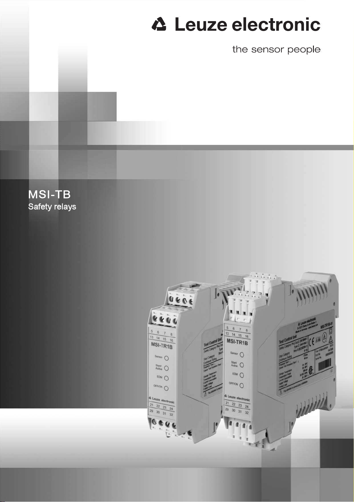
Leuze electronic MSI-TB 7
Only if the safety relay is correctly connected and correctly started up is the protective function of the
protective device ensured. To prevent misuse and resulting dangers, the following must be observed:
 These operating instructions are included in the documentation of the system on which the protective
device is mounted and are available to the operating personnel at all times.
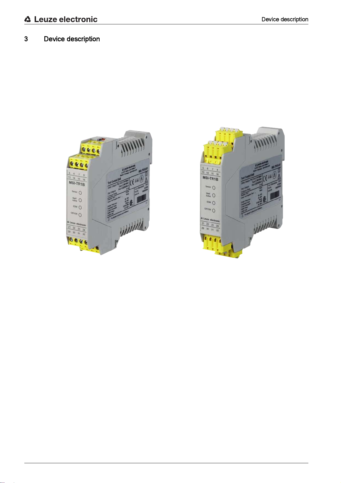
 The safety relay is used as a safety monitoring device in combination with one or more light beam
safety devices for safeguarding danger zones or points of operation on machines and systems.
 The safety relay must only be used after it has been selected in accordance with the respectively
applicable instructions and relevant standards, rules and regulations regarding labor protection and
safety at work, and after it has been installed, connected, checked and commissioned by a -
.
 The safety relay must only be connected and commissioned in accordance with its specifications
(technical data, environmental conditions, etc.).
 The Reset acknowledgment button for unlocking the start/restart interlock must be located outside
of the danger zone.
 The entire danger zone must be visible from the installation site of the acknowledgment button.
 The safety relay must be selected so that its safety-related capability meets or exceeds the required
Performance Level PL ascertained in the risk assessment (see table 14.1).
 The machine or system control must be electrically influenceable so that a switch command sent by
the safety relay results in the immediate shutdown of the dangerous movement.
 The construction of the safety relay must not be altered. When manipulating the Safety Relay, the
protective function is no longer guaranteed. Manipulating the safety relay also voids all warranty
claims against the manufacturer of the safety relay.
 The safety relay must be tested regularly by a competent person (see chapter 9 Testing).
 The safety relay must be exchanged after a maximum of 20 years. Repairs or the exchange of parts
subject to wear and tear do not extend the service life.
Any use other than that defined under the Approved purpose or which goes beyond that use is consid-
ered improper use.
Alone, the safety relay is not a complete protective device. It is not suitable for use in the following cases:
 in explosive or easily flammable atmospheres.
 on machines or systems with long stopping times.
Prerequisites for competent persons:
 They have a suitable technical education.
 They know the rules and regulations for labor protection, safety at work and safety technology and
can assess the safety of the machine.
 They know the instructions for the safety relay and the machine.
 They have been instructed by the responsible person on the mounting and operation of the machine
and of the safety relay.
Manufacturer and operating company must ensure that the machine and implemented safety relay func-
tion properly and that all affected persons are adequately informed and trained.
The type and content of all imparted information must not lead to unsafe actions by users.
The manufacturer of the machine is responsible for:
 Safe machine construction
 Safe implementation of the safety relay
 Imparting all relevant information to the operating company
 Adhering to all regulations and directives for the safe starting-up of the machine
Leuze electronic MSI-TB 8
The operator of the machine is responsible for:
 Instructing the operating personnel
 Maintaining the safe operation of the machine
 Adhering to all regulations and directives for labor protection and safety at work
 Regular testing by competent persons
Leuze electronic GmbH + Co. KG is not liable in the following cases:
 Safety relay is not used as intended
 Safety notices are not adhered to.
 Reasonably foreseeable misuse is not taken into account.
 Mounting and electrical connection are not properly performed.
 Proper function is not tested (see chapter 9 Testing).
 Changes (e.g., constructional) are made to the safety relay
Leuze electronic MSI-TB 9
The safety relays of the MSI-TB series are safety monitoring devices for electro-sensitive protective equip-
ment (ESPE), type 2, on machines with risks of bodily injury (acc. to EN 61496-1). As part of the electrical
equipment, they enable machines or systems to achieve a safe state before persons can be endangered.
The safety relay is intended for installation on the DIN rail in the cabinet and is wired via the 16 terminals .
All connection terminals are pluggable. The individual terminal blocks are mechanically coded to prevent
swapping or skewed plug in. The safety relays are available with screw terminals or spring-cage terminals.
The complete safety system consists of a safety relay and safety sensors connected to it.
Figure 3.1: MSI-TR1B with screw terminals Figure 3.2: MSI-TR1B with spring-cage terminals
Leuze electronic MSI-TB 10
a Start/active
b Active
c Transmitter
d Receiver
e Reset
f Operation with start/restart interlock
g Operation without start/restart interlock
h EDM (contactor monitoring, feedback circuit)
i Output Signal Switching Device OSSD
j Secondary switching device SSD
k Indication output Safety On
l Indication output Error
Figure 3.3: Structure of the complete safety system
Device versions:
 MSI-TR1B: standard safety monitoring device for type-2 sensors.
 MSI-TR2B: safety monitoring device with extended filter time (switches only after a continuous inter-
ruption > 130 ms; ignores small parts).
 MSI-TSB: safety monitoring device with STOP1 function.
The display elements of the safety relay simplify the start-up and fault analysis.
0V
Var . B
Var . A
+24V
St at e
Er r o r
MSI-TB
active
Receiver
0V + 24V
RES
reset
Error
active
St a r t
w/o RES
-K1
-K2
5
-A3
6
14 15 22 21 13
7 8 30 32
24 29 3123
-K2-K1
-K1
-K2
A1
A2
-K1
A1
A2
-K2
1
2
1
2
44
3
-A2
116
0V
+24V
PE
L+ L+
+ 24V
0V
PE
L- L-
3
1
Transmitter
-A1
a
b
dc
f e
h
g
j
j
i
ilk
+24V
0V
**
Figure 3.4: MSI-TR1B Figure 3.5: MSI-TR2B Figure 3.6: MSI-TSB
Leuze electronic MSI-TB 11
1 LED Sensor
2 LED Start/Active
3 LED EDM
4 LED OFF/ON
Figure 3.7: Display elements of the MSI-TB
Table 3.1: Meaning of the LEDs
1
2
3
4
Sensor green Light path free
Start/Active Yellow Restart-disable locked
EDM green EDM selected
OFF/ON green OSSD on
red OSSD off
Leuze electronic MSI-TB 12
After switching on the safety relay via the start input, the functional capability of the connected safety
sensors is cyclically monitored every two seconds.
The potential-free safety relay outputs directly send the signal for shutting down a dangerous movement.
Further integrated functions are listed in the following table.
Table 4.1: Functions of the different versions
The start/restart interlock prevents automatic start-up of the system (e.g. if the protective field is again clear
or if an interruption in the voltage supply is restored). The operating personnel must make certain that no
people are present in the danger zone before the system is manually re-enabled.
The default factory setting for this function is active.
The safety relay monitors the feedback circuits of connected contactors. The signal at the EDM input is
compared to the state of the OSSDs. While the OSSDs are switched on, the feedback circuit is open (high-
impedance); while the OSSDs are switched off, 24 V is applied to the EDM input.
The reaction at the EDM input with respect to the OSSDs is delayed by maximum 500 ms.
With the MSI-TSB variant, terminal 7 is used for the STOP1 function. The system switches on following an
interruption of the protective field. OSSD and SSD switch off with a delay of 600 ms.
Periodic function test 
Start/restart interlock selectable 
Contactor monitoring (EDM) selectable 
Indication output Safety ON 
Indication output STOP1 
Indication output Error 
Leuze electronic MSI-TB 13
Safety relays are used together with single- or multi-beam light beam safety devices, e.g. as access
guarding for danger zones. Because light beam safety devices only detect persons upon entry into the
danger zone, and not whether a person is present in the danger zone, the safety relay only triggers the
switch command upon entry of a person into a danger zone. Access guarding may therefore only be oper-
ated with activated start/restart interlock or additional safety measures must be taken.
Figure 5.1: Intervention control on packaging machinery
Leuze electronic MSI-TB 14
Figure 5.2: Access guarding / intervention control on sawing machines
Figure 5.3: Foot space protection on side-tracking shelves
Leuze electronic MSI-TB 15
The safety relay is intended for mounting on a DIN rail in a cabinet.
Prerequisites for mounting:
 Cabinet with appropriate protection rating (at least IP54).
 Sufficient space on the DIN rail.
 Arrangement of the protective device acc. to EN 999 and IEC/pr EN 61496-2 (see chapter 6.1
Arrangement of the protective device).
Snap the safety relay onto the DIN rail.
The safety relay can be connected to the safety sensors.
Optical protective devices can only perform their protective function if they are mounted with adequate
safety distance. When mounting, all delay times must be taken into account, e.g. the response times of
the light beam safety device and control elements as well as the stopping time of the machine.
The following standards specify calculation formulas:
 EN 999, The positioning of protective equipment in respect of approach speeds of parts of the
human body: mounting situation and safety distances.
 IEC/pr EN 61496-2, Active Optoelectronic Protective Devices: distance of the reflecting surfaces/
Deflecting Mirrors.
Table 6.1: Beam heights and distances
S [mm] = Safety distance
K [mm/s] = 1600 mm/s (approach speed for access guarding)
T [s] = Total time of the delay
C [mm] = 850 mm (default value for arm length)
Calculate the safety distance S for access guarding using the formula acc. to ISO 13855 or EN 999:
The protective function of the safety relay is only ensured if appropriately and professionally mounted for
the respective, intended area of application.
Only allow competent persons to install the safety relay.
Observe the relevant standards, regulations and these instructions.
2 / 500 400, 900
3 / 400 300, 700, 1100
4 / 300 300, 600, 900, 1200
Leuze electronic MSI-TB 16
S [mm] = Safety distance
ta[s] = Response time of the protective device
ti[s] = Response time of the safety relay
tm[s] = Stopping time of the machine
tt[s] = Test interval time of the safety relay
Table 6.2: Values for ti max
With multi-axis installation, the light beams must run parallel to the reference plane (e.g. floor) and must
be aligned mutually parallel.
The beam directions are to be set oppositely in each case (see figure 6.1). Otherwise, the light beams
could cause mutual interference and disturb reliable function.
a Transmitter
b Receiver
Figure 6.1: Multi-axis arrangement
ti max
MSI-TR1B 80
MSI-TR2B 150
MSI-TSB 620
If longer stopping times are determined during regular inspections, an appropriate additional time
must be added to tm.
a
a
a
b
b
b
Reflective surfaces can indirectly deflect the transmitter beams to the receiver. In this case, interruption
of the protective field is not detected.
Make certain that all reflective surfaces are the necessary minimum distance away from the protective
field.
Leuze electronic MSI-TB 17
a Required minimum distance to reflective surfaces [mm]
b Protective field width [m]
c Reflective surface
Figure 6.2: Minimum distance to reflective surfaces depending on protective field width
a Required minimum distance to reflective surfaces [mm]
b Protective field width [m]
Figure 6.3: Minimum distance to reflective surfaces as a function of the protective field width up to 10 m
a Required minimum distance to reflective surfaces [mm]
b Protective field width [m]
Figure 6.4: Minimum distance to reflective surfaces as a function of the protective field width up to 70 m
Calculate the minimum distance to reflective surfaces depending on the installation situation and
according to the following formula:
Table 6.3: Calculating the minimum distance
a
b
4° 4°
c
a
900
200
800
300
400
600
500
700
3510
b
131
a
500
3500
1000
1500
2500
2000
3000
320 40 60 70
b
131
10 30 50
b  3 m a [mm] = 131
b > 3 m a [mm] = tan(2.5°)  1000  b [m] = 43.66  b [m]
Leuze electronic MSI-TB 18
When using Deflecting Mirrors, the following must be observed:
 Range loss per Deflecting Mirror of approx. 15 %.
 Deflecting Mirrors must not be soiled.
 Environmental conditions (vapors or dust-laden air considerably limit the range).
 Arrange the Deflecting Mirror so that the optical axis is aligned with the center of the mirror (see
figure 6.5).
Figure 6.5: Arrangement of the Deflecting Mirrors
once prior to establishing the electrical connection
competent person
Table 6.4: Checklist  mounting the light beam safety device
Do the beam heights satisfy the requirements acc. to EN 999 (see table 6.1)?
Is the safety distance to the hazard location maintained (see chapter 6.1.1 Calculating
the safety distance)?
Is the minimum distance to reflective surfaces maintained (see chapter 6.1.3 Minimum
distance to reflective surfaces)?
Is it ensured that light beam safety devices cannot mutually influence one another?
Can the hazard location or the danger zone only be accessed through the protective
field?
Is it ensured that the protective field cannot be circumvented?
Do the transmitter and receiver connections point in the same direction?
Is the light beam safety device mounted acc. to the corresponding instructions provided
by the manufacturer?
Leuze electronic MSI-TB 19
Is the light beam safety device accessible for testing and replacing?
Is it ensured that the start/restart button cannot be activated from within the danger
zone?
Can the entire danger zone be seen from the installation site of the start/restart button?
Leuze electronic MSI-TB 20
The following must be observed for the current supply of the safety relay:
 Supply voltage 24 V DC ±20 %.
 Safe mains separation acc. to EN/IEC 60742 possible.
 A corresponding power supply unit handles interruptions of the supply voltage up to 10 ms in dura-
tion acc. to EN/IEC 61496-1.
The following conditions apply for the electrical connection:
 The safety relay is to be integrated in the control acc. to ISO 13849-1.
 No safety-relevant signals are switched via the message outputs.
 There are always two switching contacts integrated in the system switch-off circuit.
 Relay switching contacts are fused/protected externally according to their specifications (see
table 14.3).
For reliable and touch-safe contacts, isolate the connection ends as follows:
 Screw terminals: 7 mm
 Spring-cage terminals: 8 mm
Connected to the safety relay are 16 numbered terminals to which the cables for the various functions are
connected.
Depending on external wiring, dangerous voltages may be present at the switching outputs.
During all work at the electrical system or electronics, make certain that each voltage supply has been
interrupted and protected against being restarted.
Only allow competent persons to perform the electrical connection.
Make certain that supply and signal lines are laid separately from power lines.
Use appropriate spark extinction for contactors in the cabinet.
Observe the installation notices and operating instructions of the products that are to be connected via
the safety relay (drive motors, brakes, etc.).
Always connect light beam safety devices to an external safety relay and activate the restart interlock.
For access guarding, make certain that the restart interlock cannot be unlocked from within the danger
zone but that the danger zone can be viewed from the acknowledgment button (Reset).
Select the functions so that the safety relay is used as intended (see chapter 2.1 Approved purpose
and foreseeable improper operation).

This manual suits for next models

3

Other Leuze electronic Relay manuals

Leuze electronic MSI-TRMB User manual

Leuze electronic

Leuze electronic MSI-TRMB User manual

Leuze electronic MSI-SR-ES20-01 User manual

Leuze electronic

Leuze electronic MSI-SR-ES20-01 User manual

Leuze electronic MSI-SR5B Series User manual

Leuze electronic

Leuze electronic MSI-SR5B Series User manual

Leuze electronic MSI-SR-LC21DT03 Series User manual

Leuze electronic

Leuze electronic MSI-SR-LC21DT03 Series User manual

Leuze electronic MSI-SR5B Series User manual

Leuze electronic

Leuze electronic MSI-SR5B Series User manual

Leuze electronic ML2R-SR4 User manual

Leuze electronic

Leuze electronic ML2R-SR4 User manual

Leuze electronic MSI-SR-LC31AR Series User manual

Leuze electronic

Leuze electronic MSI-SR-LC31AR Series User manual

Popular Relay manuals by other brands

Guard master MINOTAUR MSR16R/T quick start guide

Guard master

Guard master MINOTAUR MSR16R/T quick start guide

Elko PRI-53 manual

Elko

Elko PRI-53 manual

GE L90 instruction manual

GE

GE L90 instruction manual

Basler BE1-50/51M-222 instruction manual

Basler

Basler BE1-50/51M-222 instruction manual

DOLD VARIMETER RCM Installations

DOLD

DOLD VARIMETER RCM Installations

F&F FOX HERMETIC BOX manual

F&F

F&F FOX HERMETIC BOX manual

Stelpro BA Series Installation

Stelpro

Stelpro BA Series Installation

Siemens 3RP25 operating instructions

Siemens

Siemens 3RP25 operating instructions

Honeywell 7800 SERIES manual

Honeywell

Honeywell 7800 SERIES manual

GE IFC66CD instructions

GE

GE IFC66CD instructions

Plejd LED-75 installation manual

Plejd

Plejd LED-75 installation manual

Idem SCR-7 User information

Idem

Idem SCR-7 User information

Outback Power Systems FLEXware16 Amp Maximum 250VAC product manual

Outback Power Systems

Outback Power Systems FLEXware16 Amp Maximum 250VAC product manual

GEYA GRT8-P instruction manual

GEYA

GEYA GRT8-P instruction manual

GE ACR11B instructions

GE

GE ACR11B instructions

PickData TIR Two quick start guide

PickData

PickData TIR Two quick start guide

Pandora BT-02 installation manual

Pandora

Pandora BT-02 installation manual

Dawnco series 3000 instruction manual

Dawnco

Dawnco series 3000 instruction manual

manuals.online logo
manuals.online logoBrands
  • About & Mission
  • Contact us
  • Privacy Policy
  • Terms and Conditions

Copyright 2025 Manuals.Online. All Rights Reserved.