Leuze MSI-TR1B User manual

MSI-TR1B
MSI-TR2B
Safety Relays
Original operating instructions
EN 2021/04/21 - 50124409
We reserve the right to make technical changes

© 2021
Leuze electronic GmbH + Co. KG
In der Braike 1
D-73277 Owen / Germany
Phone: +49 7021 573-0
Fax: +49 7021 573-199
http://www.leuze.com

Leuze electronic GmbH + Co. KG MSI-TR1B / MSI-TR2B 3
1 About this document. . . . . . . . . . . . . . . . . . . . . . . . . . . . . . . . . . . . . . . . . . . . . . . . . . . 5
1.1 Used symbols and signal words . . . . . . . . . . . . . . . . . . . . . . . . . . . . . . . . . . . . . . . . . . . . . . . . . . 5
1.2 Checklists . . . . . . . . . . . . . . . . . . . . . . . . . . . . . . . . . . . . . . . . . . . . . . . . . . . . . . . . . . . . . . . . . . . 5
2 Safety . . . . . . . . . . . . . . . . . . . . . . . . . . . . . . . . . . . . . . . . . . . . . . . . . . . . . . . . . . . . . . 6
2.1 Intended use and foreseeable misuse. . . . . . . . . . . . . . . . . . . . . . . . . . . . . . . . . . . . . . . . . . . . . . 6
2.1.1 Intended use . . . . . . . . . . . . . . . . . . . . . . . . . . . . . . . . . . . . . . . . . . . . . . . . . . . . . . . . . . . . . . . 6
2.1.2 Foreseeable misuse . . . . . . . . . . . . . . . . . . . . . . . . . . . . . . . . . . . . . . . . . . . . . . . . . . . . . . . . . 7
2.2 Competent persons . . . . . . . . . . . . . . . . . . . . . . . . . . . . . . . . . . . . . . . . . . . . . . . . . . . . . . . . . . . . 7
2.3 Responsibility for safety. . . . . . . . . . . . . . . . . . . . . . . . . . . . . . . . . . . . . . . . . . . . . . . . . . . . . . . . . 7
2.4 Exemption of liability . . . . . . . . . . . . . . . . . . . . . . . . . . . . . . . . . . . . . . . . . . . . . . . . . . . . . . . . . . . 8
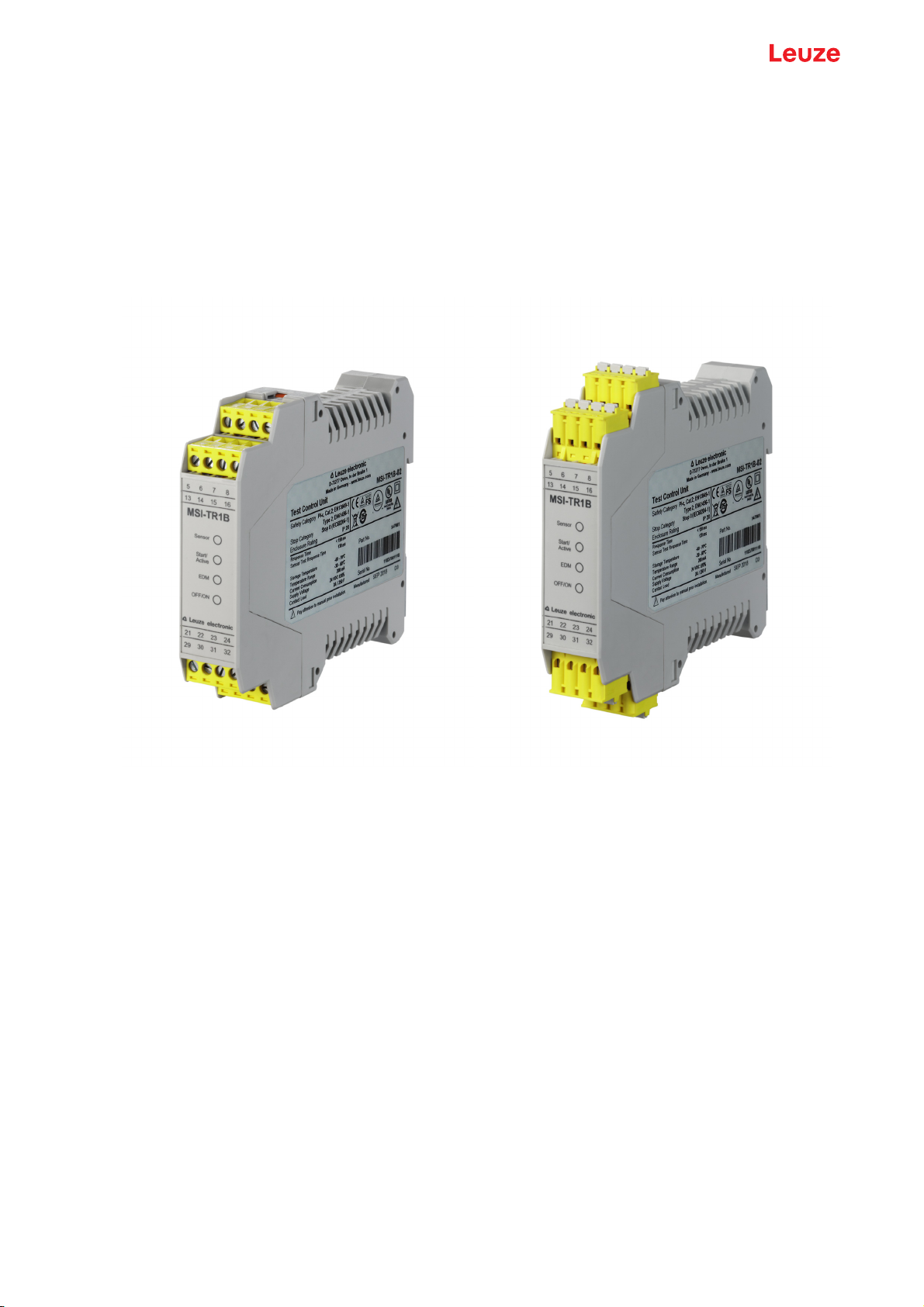
3 Device description . . . . . . . . . . . . . . . . . . . . . . . . . . . . . . . . . . . . . . . . . . . . . . . . . . . . 9
3.1 Device overview. . . . . . . . . . . . . . . . . . . . . . . . . . . . . . . . . . . . . . . . . . . . . . . . . . . . . . . . . . . . . . 10
3.2 Display elements . . . . . . . . . . . . . . . . . . . . . . . . . . . . . . . . . . . . . . . . . . . . . . . . . . . . . . . . . . . . . 10
4 Functions . . . . . . . . . . . . . . . . . . . . . . . . . . . . . . . . . . . . . . . . . . . . . . . . . . . . . . . . . . 12
4.1 Start/restart interlock (RES). . . . . . . . . . . . . . . . . . . . . . . . . . . . . . . . . . . . . . . . . . . . . . . . . . . . . 12
4.2 Contactor monitoring (EDM) . . . . . . . . . . . . . . . . . . . . . . . . . . . . . . . . . . . . . . . . . . . . . . . . . . . . 12
5 Applications . . . . . . . . . . . . . . . . . . . . . . . . . . . . . . . . . . . . . . . . . . . . . . . . . . . . . . . . 13
5.1 Access guarding . . . . . . . . . . . . . . . . . . . . . . . . . . . . . . . . . . . . . . . . . . . . . . . . . . . . . . . . . . . . . 13
6 Mounting. . . . . . . . . . . . . . . . . . . . . . . . . . . . . . . . . . . . . . . . . . . . . . . . . . . . . . . . . . . 15
6.1 Arrangement of the protective device . . . . . . . . . . . . . . . . . . . . . . . . . . . . . . . . . . . . . . . . . . . . . 15
6.1.1 Calculating the safety distance . . . . . . . . . . . . . . . . . . . . . . . . . . . . . . . . . . . . . . . . . . . . . . . . 15
6.1.2 Multi-axis arrangement . . . . . . . . . . . . . . . . . . . . . . . . . . . . . . . . . . . . . . . . . . . . . . . . . . . . . . 16
6.1.3 Minimum distance to reflective surfaces . . . . . . . . . . . . . . . . . . . . . . . . . . . . . . . . . . . . . . . . . 16
6.1.4 Checklist – mounting the protective sensor . . . . . . . . . . . . . . . . . . . . . . . . . . . . . . . . . . . . . . . 18
7 Electrical connection . . . . . . . . . . . . . . . . . . . . . . . . . . . . . . . . . . . . . . . . . . . . . . . . . 20
7.1 Terminal assignments . . . . . . . . . . . . . . . . . . . . . . . . . . . . . . . . . . . . . . . . . . . . . . . . . . . . . . . . . 20
7.2 Configuration of the EDM and RES operating modes . . . . . . . . . . . . . . . . . . . . . . . . . . . . . . . . . 21
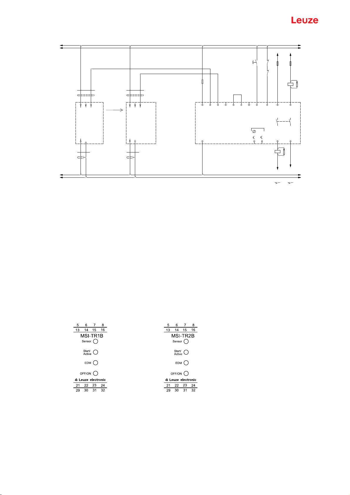
7.3 Circuit diagram examples . . . . . . . . . . . . . . . . . . . . . . . . . . . . . . . . . . . . . . . . . . . . . . . . . . . . . . 22
8 Starting up the device. . . . . . . . . . . . . . . . . . . . . . . . . . . . . . . . . . . . . . . . . . . . . . . . . 24
8.1 Switching on . . . . . . . . . . . . . . . . . . . . . . . . . . . . . . . . . . . . . . . . . . . . . . . . . . . . . . . . . . . . . . . . 24
8.2 Unlocking start/restart interlock (RES). . . . . . . . . . . . . . . . . . . . . . . . . . . . . . . . . . . . . . . . . . . . . 24
9 Testing . . . . . . . . . . . . . . . . . . . . . . . . . . . . . . . . . . . . . . . . . . . . . . . . . . . . . . . . . . . . 25
9.1 Before the initial start-up and following modifications . . . . . . . . . . . . . . . . . . . . . . . . . . . . . . . . . 25
9.1.1 Checklist – initial start-up . . . . . . . . . . . . . . . . . . . . . . . . . . . . . . . . . . . . . . . . . . . . . . . . . . . . . 25
9.2 To be performed periodically by a competent person . . . . . . . . . . . . . . . . . . . . . . . . . . . . . . . . . 26
9.3 To be performed daily by the operating personnel . . . . . . . . . . . . . . . . . . . . . . . . . . . . . . . . . . . 27
9.3.1 Check list – daily or at change of shift . . . . . . . . . . . . . . . . . . . . . . . . . . . . . . . . . . . . . . . . . . . 27
10 Maintenance. . . . . . . . . . . . . . . . . . . . . . . . . . . . . . . . . . . . . . . . . . . . . . . . . . . . . . . . 28
11 Troubleshooting . . . . . . . . . . . . . . . . . . . . . . . . . . . . . . . . . . . . . . . . . . . . . . . . . . . . . 29
11.1 What to do in case of failure? . . . . . . . . . . . . . . . . . . . . . . . . . . . . . . . . . . . . . . . . . . . . . . . . . . . 29
11.2 Operating indicators of the LEDs. . . . . . . . . . . . . . . . . . . . . . . . . . . . . . . . . . . . . . . . . . . . . . . . . 29

Leuze electronic GmbH + Co. KG MSI-TR1B / MSI-TR2B 4
12 Disposing . . . . . . . . . . . . . . . . . . . . . . . . . . . . . . . . . . . . . . . . . . . . . . . . . . . . . . . . . . 30
13 Service and support . . . . . . . . . . . . . . . . . . . . . . . . . . . . . . . . . . . . . . . . . . . . . . . . . . 31
14 Technical data . . . . . . . . . . . . . . . . . . . . . . . . . . . . . . . . . . . . . . . . . . . . . . . . . . . . . . 32
14.1 Dimensions . . . . . . . . . . . . . . . . . . . . . . . . . . . . . . . . . . . . . . . . . . . . . . . . . . . . . . . . . . . . . . . . . 34
15 Order guide . . . . . . . . . . . . . . . . . . . . . . . . . . . . . . . . . . . . . . . . . . . . . . . . . . . . . . . . 35
16 Declaration of Conformity. . . . . . . . . . . . . . . . . . . . . . . . . . . . . . . . . . . . . . . . . . . . . . 36

About this document
Leuze electronic GmbH + Co. KG MSI-TR1B / MSI-TR2B 5
1 About this document
1.1 Used symbols and signal words
Table 1.1: Warning symbols and signal words
Table 1.2: Other symbols
Table 1.3: Terms and abbreviations
1.2 Checklists
The checklists (see chapter 9 "Testing") serve as a reference for the machine manufacturer or supplier.
They replace neither testing of the complete machine or system prior to the initial start-up nor their periodic
testing by a competent person. The checklists contain minimum testing requirements. Depending on the
application, other tests may be necessary.
Symbol indicating dangers to persons
NOTE Signal word for property damage
Indicates dangers that may result in property damage if the measures for danger
avoidance are not followed.
CAUTION Signal word for minor injuries
Indicates dangers that may result in minor injury if the measures for danger avoid-
ance are not followed.
WARNING Signal word for serious injury
Indicates dangers that may result in severe or fatal injury if the measures for danger
avoidance are not followed.
DANGER Signal word for life-threatening danger
Indicates dangers with which serious or fatal injury is imminent if the measures for
danger avoidance are not followed.
Symbol for tips
Text passages with this symbol provide you with further information.
Symbol for action steps
Text passages with this symbol instruct you to perform actions.
AOPD Active Optoelectronic Protective Device
Active Opto-electronic Protective Device
EDM External Device Monitoring
OSSD Output Signal Switching Device
SSD Secondary Switching Device
RES Start/REStart interlock
PFHDProbability of a dangerous failure per hour
Probability of dangerous Failure per Hour
MTTFdMean time to dangerous failure
(Mean Time To dangerous Failure)
PL Performance Level

Safety
Leuze electronic GmbH + Co. KG MSI-TR1B / MSI-TR2B 6
2 Safety
Before using the safety sensor, a risk assessment must be performed according to valid standards (e.g.
EN ISO 12100, EN ISO 13849-1, EN/IEC 61508, EN/IEC 62061). The result of the risk assessment deter-
mines the required safety level of the safety relay (see table 14.1). For mounting, operating and testing,
this document as well as all applicable national and international standards, regulations, rules and direc-
tives must be observed. Relevant and supplied documents must be observed and handed to the affected
personnel.
Before working with the safety relay, completely read and understand the documents applicable to your
task.
In particular, the following national and international legal regulations apply for the start-up, technical
inspections and work with safety relays:
• Machinery directive 2006/42/EC
• Low voltage directive 2014/35/EU
• Electromagnetic compatibility 2014/30/EU
• Use of work equipment directive 2009/104/EC
• OSHA 1910 Subpart 0
• Safety regulations
• Accident-prevention regulations and safety rules
• Ordinance on Industrial Safety and Health and employment protection act
• Product safety law (Produktsicherheitsgesetz)
2.1 Intended use and foreseeable misuse
2.1.1 Intended use
NOTE
For safety-related information you may also contact local authorities (e.g., industrial inspec-
torate, employer's liability insurance association, labor inspectorate, occupational safety and
health authority).
DANGER
Electrically live systems pose a risk of electric shock!
During all conversions, maintenance work and inspections, make certain that the voltage sup-
ply is interrupted and protected against being restarted again.
Only have work on the electrical system and electronics performed by a competent person.
WARNING
A running machine may result in serious injury!
Make certain that the safety relay is correctly connected and that the protective function of the
protective device is ensured.
Make certain that, during all conversions, maintenance work and inspections, the system is
securely shut down and protected against being restarted.

Safety
Leuze electronic GmbH + Co. KG MSI-TR1B / MSI-TR2B 7
Only if the safety relay is correctly connected and correctly started up is the protective function of the
protective device ensured. To prevent misuse and resulting dangers, the following must be observed:
• These operating instructions are included in the documentation of the system on which the protective
device is mounted and are available to the operating personnel at all times.
• The safety relay is used as a safety monitoring device in combination with one or more light beam
safety devices for safeguarding danger zones or points of operation on machines and systems.
• The safety relay must only be used after it has been selected in accordance with the respectively
applicable instructions and relevant standards, rules and regulations regarding labor protection and
safety at work, and after it has been installed, connected, checked and commissioned by a compe-
tent person.
• The safety relay must only be connected and commissioned in accordance with its specifications
(technical data, environmental conditions, etc.).
• The acknowledgment button for unlocking the start/restart interlock must be located outside of the
danger zone.
• The entire danger zone must be visible from the installation site of the acknowledgment button.
• The safety relay must be selected so that its safety-related capability meets or exceeds the required
Performance Level PL ascertained in the risk assessment (see table 14.1).
• The machine or system control must be electrically influenceable so that a switch command sent by
the safety relay results in the immediate shutdown of the dangerous movement.
• The construction of the safety relay must not be altered. When manipulating the safety relay, the pro-
tective function is no longer guaranteed. Manipulating the safety relay also voids all warranty claims
against the manufacturer of the safety relay.
• The safety relay must be tested regularly by a competent person (see chapter 9 "Testing").
• The safety relay must be exchanged after a maximum of 20 years. Repairs or the exchange of wear
parts do not extend the mission time.
2.1.2 Foreseeable misuse
Any use other than that defined under the “Approved purpose” or which goes beyond that use is consid-
ered improper use.
Alone, the safety relay is not a complete protective device. It is not suitable for use in the following cases:
• in explosive or easily flammable atmospheres.
• on machines or systems with long stopping times.
2.2 Competent persons
Prerequisites for competent persons:
• They have a suitable technical education.
• They know the rules and regulations for labor protection, safety at work and safety technology and
can assess the safety of the machine.
• They know the instructions for the safety relay and the machine.
• They have been instructed by the responsible person on the mounting and operation of the machine
and of the safety relay.
2.3 Responsibility for safety
Manufacturer and operating company must ensure that the machine and implemented safety relay func-
tion properly and that all affected persons are adequately informed and trained.
The type and content of all imparted information must not lead to unsafe actions by users.
The manufacturer of the machine is responsible for:
• Safe machine construction.
• Safe implementation of the safety relay.
• Imparting all relevant information to the operating company.
• Adhering to all regulations and directives for the safe starting-up of the machine.

Safety
Leuze electronic GmbH + Co. KG MSI-TR1B / MSI-TR2B 8
The operator of the machine is responsible for:
• Instructing the operating personnel.
• Maintaining the safe operation of the machine.
• Adhering to all regulations and directives for labor protection and safety at work.
• Regular testing by competent persons.
2.4 Exemption of liability
Leuze electronic GmbH + Co. KG is not liable in the following cases:
• Safety relay is not used as intended.
• Safety notices are not adhered to.
• Reasonably foreseeable misuse is not taken into account.
• Mounting and electrical connection are not properly performed.
• Proper function is not tested (see chapter 9 "Testing").
• Changes (e.g., constructional) are made to the safety relay.

Device description
Leuze electronic GmbH + Co. KG MSI-TR1B / MSI-TR2B 9
3 Device description
The safety relays of the MSI-TRxB series are safety monitoring devices for electro-sensitive protective
equipment (ESPE), type 2, on machines with risks of bodily injury (acc. to EN 61496-1:2013). As part of
the electrical equipment, they enable machines or systems to achieve a safe state before persons can be
endangered.
The safety relay is intended for installation on the DIN rail in the cabinet and is wired via the 16 terminals.
All connection terminals are pluggable. The individual terminal blocks are mechanically coded to prevent
swapping or skewed plug in. The safety relays are available with screw terminals or spring-cage terminals.
The complete safety system consists of a safety relay and safety sensors connected to it.
Figure 3.1: MSI-TR1B-01 with screw terminals Figure 3.2: MSI-TR1B-02 with spring-cage termi-
nals

Device description
Leuze electronic GmbH + Co. KG MSI-TR1B / MSI-TR2B 10
a Single light beam safety device transmitter (SLS 46C)
b Single light beam safety device receiver (SLE 46C)
c Safety relay for type 2 evaluation (MSI-TRxB)
d Activation of the transmitter and testing of the single light beam safety device
e Evaluation of the switching output of the single light beam safety device
f Operating mode: restart interlock (RES) active
g External reset button for manually resetting the protective device
h Monitoring of external contactor contacts (EDM)
i Potential-free normally open contacts with positive opening for the safe shutdown of, e.g., actuators
Figure 3.3: Example setup of the complete safety system with EDM and manual reset of the safety func-
tion (restart interlock).
3.1 Device overview
Device versions:
• MSI-TR1B: standard safety monitoring device for type-2 sensors.
• MSI-TR2B: safety monitoring device with extended filter time (switches only after a continuous inter-
ruption > 130 ms; ignores small parts).
3.2 Display elements
The display elements of the safety relay simplify start-up and fault analysis.
1
2
-F97
21
22
-K76
8
21
22
-K77
9
-F98
A1
A2
-K76
-F99
A1
A2
-K77
21 22 8
21 22 8
15
0V
13
Error
14 29
EDM
424
PE
7
Reset
safetysafety
0V
BN
22
A5
L+
31
+24V
23
L-
Transmitter
activationactivation
+24V
-W1
MODE
OSSD-1
-W1
SSD-1SSD-2
Diagnosis
OSSD-2
NC
L-
Leuze
0V
0V
0V
SH
BU
+24V
SH
BK
L+
BK
BU
OUT
-W2
0V
MSI-TRxB-0x
-W2
16
4
+24V
30
Receiver
A1 2
active
A3
State
6
FE
21
BN
FE
*
SLE46C
8
MSI
restartrestart
PE
3
5
*
21
Automatic
resetreset
Leuze
SLS46C
1
Leuze
3
0V
32
+24V
Saftey on
Manual
resetreset
DEF
GHI JK
L
Figure 3.4: MSI-TR1B Figure 3.5: MSI-TR2B

Device description
Leuze electronic GmbH + Co. KG MSI-TR1B / MSI-TR2B 11
1 LED "Sensor"
2 LED "Start/Active"
3 LED "EDM"
4 LED "OFF/ON"
Figure 3.6: Display elements of the MSI-TRxB
Table 3.1: Meaning of the LEDs
1
2
3
4
LED Color Description
Sensor Green Light path free
Start/Active Yellow Start / restart interlock (RES) locked
EDM Green EDM selected
OFF/ON Green OSSD on
Red OSSD off

Functions
Leuze electronic GmbH + Co. KG MSI-TR1B / MSI-TR2B 12
4 Functions
After switching on the safety relay via the start input, the functional capability of the connected safety
sensors is cyclically monitored every two seconds.
The potential-free safety relay outputs are intended for shutting down a dangerous movement. Further
integrated functions are listed in the following table.
Table 4.1: Functions of the different versions
4.1 Start/restart interlock (RES)
The start/restart interlock prevents automatic start-up of the system (e.g. if the protective field is again clear
or if an interruption in the voltage supply is restored). The operating personnel must make certain that no
people are present in the danger zone before the system is manually re-enabled.
The default factory setting for this function is active.
4.2 Contactor monitoring (EDM)
The safety relay monitors the feedback circuits of connected contactors. The signal at the EDM input is
compared to the state of the OSSDs. While the OSSDs are switched on, the feedback circuit is open (high-
impedance); while the OSSDs are switched off, 24 V is applied to the EDM input.
The reaction at the EDM input with respect to the OSSDs is delayed by maximum 500 ms.
Function MSI-TR1B MSI-TR2B
Periodic function test
Start/restart interlock (RES), selectable
Contactor monitoring (EDM), selectable
Indication output "Safety ON"
"Error" signal output

Applications
Leuze electronic GmbH + Co. KG MSI-TR1B / MSI-TR2B 13
5 Applications
5.1 Access guarding
Safety relays are used together with single- or multiple light beam safety devices, e.g. as access guarding
for danger zones. Because protective sensors only detect persons upon entry into the danger zone, and
not whether a person is present in the danger zone, the safety relay only triggers the switch command
upon entry of a person into a danger zone. Access guarding may therefore only be operated with activated
start/restart interlock or additional safety measures must be taken.
Figure 5.1: Intervention control on packaging machinery

Applications
Leuze electronic GmbH + Co. KG MSI-TR1B / MSI-TR2B 14
Figure 5.2: Access guarding / intervention control on sawing machines
Figure 5.3: Foot-space protection on side-tracking shelves

Mounting
Leuze electronic GmbH + Co. KG MSI-TR1B / MSI-TR2B 15
6 Mounting
The safety relay is intended for mounting on a DIN rail in the switch cabinet.
Prerequisites for mounting:
• Switch cabinet with appropriate degree of protection (at least IP54).
• Sufficient space on the DIN rail.
• Arrangement of the protective device acc. to EN ISO 13855 and EN 61496-2:2013 (see chapter 6.1
"Arrangement of the protective device").
Snap the safety relay onto the DIN rail.
The safety relay can be connected to the safety sensors.
6.1 Arrangement of the protective device
Optical protective devices can only perform their protective function if they are mounted with adequate
safety distance. When mounting, all delay times must be taken into account, e.g. the response times of
the protective sensor and control elements as well as the stopping time of the machine.
The following standards specify calculation formulas:
• EN ISO 13855 "The positioning of protective devices in respect of approach speeds of parts of the
human body": mounting situation and safety distances.
• EN 61496-2:2013, "Active optoelectronic protective devices": distance of the reflecting surfaces/
deflecting mirrors.
Table 6.1: Beam heights and distances
6.1.1 Calculating the safety distance
General formula for calculating the safety distance S of an Optoelectronic Protective Device acc. to
EN ISO 13855:
S [mm] = Safety distance
K [mm/s] = 1600 mm/s (approach speed for access guarding)
T [s] = Total time of the delay
C [mm] = 850 mm (default value for arm length)
Calculate the safety distance S for access guarding using the formula acc. to ISO 13855 or EN 999:
WARNING
Improper mounting may result in serious injury!
The protective function of the safety relay is only ensured if appropriately and professionally
mounted for the respective, intended area of application.
Only allow competent persons to install the safety relay.
Observe the relevant standards, regulations and these instructions.
Number of beams/beam distance [mm] Beam heights in accordance with EN ISO 13855
[mm]
2 / 500 400, 900
3 / 400 300, 700, 1100
4 / 300 300, 600, 900, 1200
SKTC+=

Mounting
Leuze electronic GmbH + Co. KG MSI-TR1B / MSI-TR2B 16
S [mm] = Safety distance
ta[s] = Response time of the protective device
ti[s] = Response time of the safety relay
tm[s] = Machine stopping time
tt[s] = Test interval time of safety relay
Table 6.2: Values for ti max
6.1.2 Multi-axis arrangement
Figure 6.1: With multi-axis installation, the light beams must run parallel to the reference plane (e.g.
floor) and must be aligned mutually parallel.
The beam directions are to be set oppositely in each case (See Figure 6.2:). Otherwise, the light beams
could cause mutual interference and disturb reliable function.
a Transmitter
b Receiver
Figure 6.2: Multi-axis arrangement
6.1.3 Minimum distance to reflective surfaces
Device ti max [ms]
MSI-TR1B 80
MSI-TR2B 150
NOTE
If longer stopping times are determined during regular inspections, an appropriate additional
time must be added to tm.
S 1600 mm tatitmt++
t
+850 mm+=
a
a
a
b
b
b
WARNING
Failure to maintain minimum distances to reflective surfaces may result in serious injury!
Reflective surfaces can indirectly deflect the transmitter beams to the receiver. In this case, inter-
ruption of the protective field is not detected.
Make certain that all reflective surfaces are the necessary minimum distance away from the
protective field.

Mounting
Leuze electronic GmbH + Co. KG MSI-TR1B / MSI-TR2B 17
a Required minimum distance to reflective surfaces [mm]
b Protective field width [m]
c Reflective surface
Figure 6.3: Minimum distance to reflective surfaces depending on protective field width
a Required minimum distance to reflective surfaces [mm]
b Protective field width [m]
Figure 6.4: Minimum distance to reflective surfaces as a function of the protective field width up to 10 m
a Required minimum distance to reflective surfaces [mm]
b Protective field width [m]
Figure 6.5: Minimum distance to reflective surfaces as a function of the protective field width up to 70 m
Calculate the minimum distance to reflective surfaces depending on the installation situation and
according to the following formula:
Table 6.3: Calculating the minimum distance
a
b
4° 4°
c
a
400
500
600
700
3510
b
262
a
500
3500
1000
1500
2500
2000
3000
320 40 60 70
b
262
10 30 50
Distance (b) transmitter-
receiver
Calculation of the minimum distance (a) to reflective surfaces
b3m a[mm]=262
b>3m a[mm]=tan(5°)1000 b [m] = 43.66 b[m]

Mounting
Leuze electronic GmbH + Co. KG MSI-TR1B / MSI-TR2B 18
Deflecting mirrors
When using deflecting mirrors, the following must be observed:
• Range loss per deflecting mirror of approx. 15 %.
• Deflecting mirrors must not be soiled.
• Environmental conditions (vapors or dust-laden air considerably limit the range).
• Arrange the deflecting mirror so that the optical axis is aligned with the center of the mirror
(See Figure 6.6:).
Figure 6.6: Arrangement of the deflecting mirrors
6.1.4 Checklist – mounting the protective sensor
Interval: once prior to establishing the electrical connection
Tester: competent person
Table 6.4: Checklist – mounting the protective sensor
Items on the check list Yes No
Do the beam heights satisfy the requirements acc. to EN ISO 13855 (see table 6.1)?
Is the safety distance to the point of operation maintained (see chapter 6.1.1 "Calculat-
ing the safety distance")?
Is the minimum distance to reflective surfaces maintained (see chapter 6.1.3 "Minimum
distance to reflective surfaces")?
Is it ensured that protective sensors cannot mutually influence one another?
Can the point of operation or the danger zone only be accessed through the protective
field?
Is it ensured that the protective field cannot be circumvented?
Do the transmitter and receiver connections point in the same direction?
Is the protective sensor mounted acc. to the corresponding instructions provided by the
manufacturer?

Mounting
Leuze electronic GmbH + Co. KG MSI-TR1B / MSI-TR2B 19
Is the protective sensor accessible for testing and replacing?
Is it ensured that the reset button cannot be activated from within the danger zone?
Can the entire danger zone be
n from the installation site of the reset button?
Items on the check list Yes No

Electrical connection
Leuze electronic GmbH + Co. KG MSI-TR1B / MSI-TR2B 20
7 Electrical connection
The following must be observed for the current supply of the safety relay:
• Supply voltage 24 V DC ±20 %.
• Safe mains separation acc. to EN/IEC 60742 possible.
• A corresponding power supply unit handles interruptions of the supply voltage up to 10 ms in dura-
tion acc. to EN/IEC 61496-1.
The following conditions apply for the electrical connection:
• The safety relay is to be integrated in the control acc. to EN ISO 13849-1.
• No safety-relevant signals are switched via the message outputs.
• There are always two switching contacts integrated in the system switch-off circuit.
• Relay switching contacts are fused/protected externally according to their specifications (see
table 14.3).
Connecting the signal lines
For reliable and touch-safe contacts, isolate the connection ends as follows:
• Screw terminals: 7 mm
• Spring-cage terminals: 8 mm
7.1 Terminal assignments
Connected to the safety relay are 16 numbered terminals to which the cables for the various functions are
connected.
DANGER
Risk of death by electric shock!
Depending on external wiring, dangerous voltages may be present at the switching outputs.
During all work at the electrical system or electronics, make certain that each voltage supply has
been interrupted and protected against being restarted.
WARNING
Improper electrical connection may result in serious injury!
Only allow competent persons to perform the electrical connection.
Make certain that supply and signal lines are laid separately from power lines.
Use appropriate spark extinction for contactors in the cabinet.
Observe the installation notices and operating instructions of the products that are to be
connected via the safety relay (drive motors, brakes, etc.).
WARNING
Selecting the wrong functions may result in serious accidents!
Always connect protective sensors to an external safety relay and activate the restart inter-
lock.
For access guarding, make certain that the restart interlock cannot be unlocked from within
the danger zone but that the danger zone can be viewed from the acknowledgment button
(reset button).
Select the functions so that the safety relay is used as intended (see chapter 2.1 "Intended use
and foreseeable misuse").
This manual suits for next models
1
Table of contents
Other Leuze Relay manuals