Level Pro 100 Series User manual

INSTALLATION MANUAL
100 Series Submersible Pressure Sensors
Chemical Resistant Industrial Level Sensors + Displays
ContinuousSubmersibleLevel Transmitter
Levelpro-Sensors Manual
AL R1 R2
MENU
ESC
ENTER
TVLSeries
Level Process Display
Controller

INTRODUCTION
Levelpro Submersible Level Transmitters are manufactured for years of trouble free service in tough industrial applications. The 100
Series Levelpro Submersible Level Transmitter measures the height of liquid above the position of the sensing diaphragm of the
transmitter located inside the tank referenced to atmospheric pressure. The transmitter consists of a ceramic piezo-resistive sensing
element, encased in PVC, PVDF, PP, or 316 SS housing.
The Large Diameter flush diaphragm is non-clogging and damage resistant to floating solids.
The 100 Series transmitter is equipped with a high tensile strength FEP (Teflon) shielded and vented cable. and contains an internal
non-wetted weight and utilizes Kalrez O-ring seals The Ventilation tube in the cable automatically compensates for changes in
atmospheric pressure above the tank.
Excellent Chemical Compatibility PVC | PVDF | PP | 316SS
Slim Design for Tight Applications
Large Diameter, Non-Clogging, Damage Resistant, Ceramic Diaphragm
This operating manual contains important information on proper usage of the device. Read this operating manual carefully before
installing and starting up the pressure measuring device.
Adhere to the safety notes and operating instructions which are given in the operating manual. Additionally applicable regulations
regarding occupational safety, accident preven-tion as well as national installation standards and engineer-ing rules must be complied
with!
This operating manual is part of the device, and should be kept nearest its location, always accessible to all employees.
This operating manual is copyrighted. The contents of this operating manual reflect the version available at the time of printing. It has
been issued to our best knowledge. Levelpro is not liable for any incorrect statements and their effects.
By non observance of the operating manual, inappropriate use, modification or damage, no liability is assumed and warranty claims will
be excluded.
1. GENERAL INFORMATION
1.1 Information on the Operating Manual
DANGER! – Dangerous Situation, which may result in death or serious injuries
WARNING! – Potentially Dangerous Situation, which may result in death or serious injuries
CAUTION! – Potentially Dangerous Situation, which may result in minor injuries
CAUTION! – Potentially Dangerous Situation, which may result in physical Damage
1.2 Symbols Used
1.3 Limitation of Liability
The Levelpro Level Sensors have been developed for continuous level measurement. It is the operator's responsibility to check and
verify the suitability of the device for the intended application. If any doubts remain, please contact our technical department in order to
ensure proper usage and compatibility . Levelpro is not liable for any incorrect selections and their effects!
1.4 Intended Use
NOTE : �ps and informa�on to ensure a failure-free opera�on
WARNING! To avoid operator hazards and damages of the device, the following instructions have to be worked out by
qualified technical personnel.
ContinuousSubmersibleLevel Transmitter
Levelpro-Sensors Manual
01
© Icon Process Controls Ltd. All Rights Reserved

Permissible media are liquids (no solids or frozen media), specified in the data sheet. In addition it has to be ensured, that this medium is
compatible with the any wetted parts of the level sensor.
The technical data listed in the current data sheet are engaging and must be complied with. If the data sheet is not available, please
order or download it from our homepage. (http://www.iconprocon.com)
Please verify that all listed parts are undamaged included in the delivery and check for consistency specified in your order:
1.5 Package contents
The device can be identified by its
manufacturing label.
WARNING! – Danger through improper usage!
Probe
Mounting Instructions
2. PRODUCT IDENTIFICATION
3.1 Mounting and safety instructions
3. MECHANICAL INSTALLATION
Fig. 1 Manufacturing Label
Input :
Type:
Code:
SN: 0143693
0 - 10 m WC
Output : 4-20mA 2-wire
Supply:
Vs+: Red
Connector Pinout:
Vs -: Black
Shield: Yellow-Green
12-36 VDC
pressure measurement
www. iconprocon.com
Nominal
Pressure Range
Signal
Supply
Type
Designation
Ordering
Code
Serial
Number
Cable Colours
WARNING! Install the device only when depressurized and not connected to power source!
WARNING!This device may only be installed by qualified technical personnel who has read and under stood the operating
manual!
Handle this high sensitive electronic precision measuring device with care, both in packed and unpacked condition!
There are no modifications/changes to be made on the device.
Do not throw the package/device!
To avoid damaging the diaphragm, remove packaging and protective cap directly before starting assembly.
The delivered protective cap has to be stored!
Place the Protective Cap on the pressure port again immediately after disassembling.
Handle the unprotected diaphragm very carefully - it is very sensitive and may be easily damaged.
Do not use any force when installing the device to prevent damage of the device and the plant!
When placing the device into operation or after mainte nance work, the probe has to be submerged slowly into the medium!
A rough immersion into the medium can damage or destroy the diaphragm.
If there is any danger of damage by lightning or overpressure when the device is installed outdoor, we suggest putting a
sufficiently Sized overpressure protection device between the supply or switch cabinet and the device
ContinuousSubmersibleLevel Transmitter
Levelpro-Sensors Manual
02
© Icon Process Controls Ltd. All Rights Reserved

Carefully remove the pressure measuring device from the package and dispose of the package properly.
Mount the device according to your demands.
If the probe has been delivered without mounting accessories. Please Contact Icon Process Controls(www. iconprocon.com)
for tank connection LP100 Junction Box
3.2 Installation Steps for Probe
For the protection of the diaphragm, some of the probes have a protection device. The device must be removed before installation
3.3 Removing the Protection Cap
If it is necessary for your application to remove the protection cap, this has to be done with utmost care. To prevent damage of
the diaphragm, please follow these instructions.
ContinuousSubmersibleLevel Transmitter
Levelpro-Sensors Manual
03
3.4 Installation Procedure - Sensors and Junction Box
1 2 3
4 5 6
Take Junction Box Open Lid
Carefully Lower the 100 Series
2" NPT
Connection
Thread into Fitting
Open Lid
1. Feed 100 Series Wire Redand
Blackin Junction Box
2. Tighten Cord Grip
Connection
100 Series Wire
Red wire 3 Terminals
Black wire 2 Terminals
Do Not Bend
Capillary Reference
Tube
100 Series
Sensor
100 Series
Sensor
Lid is Tethered
12
3 4
5 6
© Icon Process Controls Ltd. All Rights Reserved
1/4 Turn
+-
LP100 Junction Box

The default for the Input is 4 mA and this will not change.
Typically will be the tank is empty (example. 000.0 Gallons, 000.0 inches, 000.0 feet etc.).
ypically will be when the tank is full (example: 500.0 Gallons, 120.0 inches, 10.0 feet, etc.)
Shielded cable is recommended for control loop wiring.
Use the Red wire as the (+) and the Black wire as the (-)
Wiring to the Levelpro Series Tank Level Controller
External
Display
-+
+
+
4-20
Output
Examples : Pump Shut-Off
High Level Alarm
4. WIRING DIAGRAM
Wiring to a Loop Powered Display :
AL R1 R2
MENU
ESC
ENTER
100 Series Level Sensors
1 2
3 4
5 6
AL R1 R2
MENU
ESC
ENTER
16 15 14 13 12 11 10 9 8 7 6 5 4 3 2 1
Power Supply 120VAC
Terminal 1 & 2
TVL Channel Terminals
TVL Series
Level Process Display | Controller
Jump Wire
3&8
Alarm Pump Magnetic
Contactor Relay
Alarm
ProAlert-1000
Audible / Vesual
Output Relays
Output Relays
Wiring LP 100
Junction Box
MENU
ESC
ENTER
ContinuousSubmersibleLevel Transmitter
Levelpro-Sensors Manual
04
© Icon Process Controls Ltd. All Rights Reserved

4.2 Connection Diagram
13141516 12 11 10 09 08 07 06 05 04 03 02 01
Power Supply
120VAC
04 03 02 01
TVF Terminals
Red wire Terminal 8
Black Wire Terminal 11
Junction Box Terminals
Red wire Terminal 6
Black Wire Terminal 1
TVF Terminals
Black Wire Terminal 1
White Wire Terminal 2
Sentinel LTE Telemetry100 Series
120 VAC Power Supply
TVLChannel Terminals
Junction Box Terminals
12
3 4
5 6
Junction Box Terminals
Green wire Terminal 5
Black Wire Terminal 4
Junction Box Terminals
Red wire Terminal 3
Black Wire Terminal 2
13 12 11 10 09 08 07
12
3 4
5 6
12
3 4
5 6
12
3 4
5 6
4.1 Wiring Diagram
2-wire-system (current)
P
Supply + +
Supply -
Vs
I
(Red)
(White)
A
24VDC
2-wire-system
(current) HART.
Vs
Supply +
Supply -
P+
I
Inferface
HART
PC
R
A
24VDC
2-Wire-System | 4-20mA
Sentinel LTE
Telemetry
Supply +
Supply -
Vs
Green
Black
100 Series with Sentinel LT Series
100 Series Sentinel LT Series
ContinuousSubmersibleLevel Transmitter
Levelpro-Sensors Manual
05
© Icon Process Controls Ltd. All Rights Reserved

5. SERVICE | REPAIR
5.1 Return
Before every return of your device, whether for recalibration, decalcification, modifications or repair, it has to be cleaned carefully. You
have to enclose a notice of return with detailed defect description when sending the device. If your device came in contact with harmful
substances, a declaration of decontamination is additionally required. Appropriate forms can be downloaded from our homepage
(www.iconprocon.com). Should you dispatch a device without a declaration of decontamination and if there are any doubts in our
service department regarding the used medium, repair will not be started until an acceptable declaration is sent.
The warranty conditions are subject to the legal warranty period of 12 months from the date of delivery. In case of improper use,
modifications of or damages to the device, we do not accept warranty claims. Damaged diaphragms will also not be accepted.
Furthermore, defects due to normal wear are not subject to warranty services.
7. WARRANTY CONDITIONS
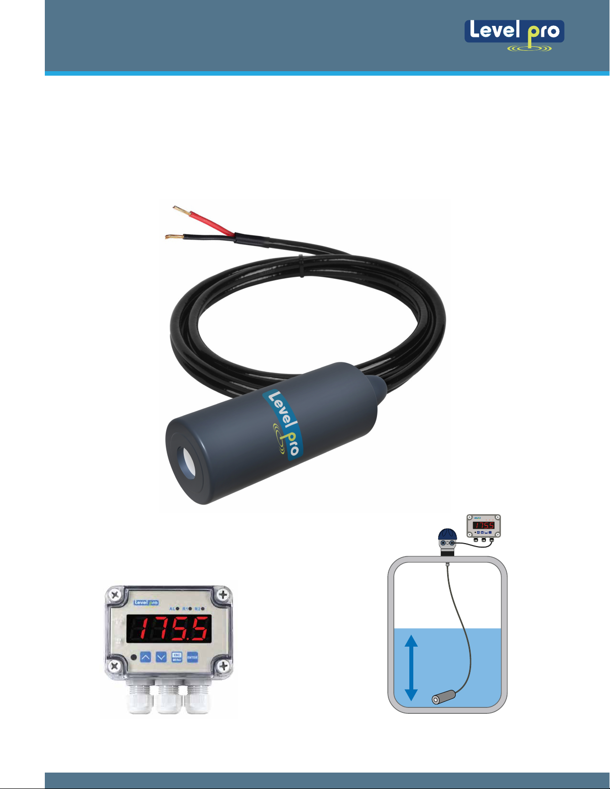
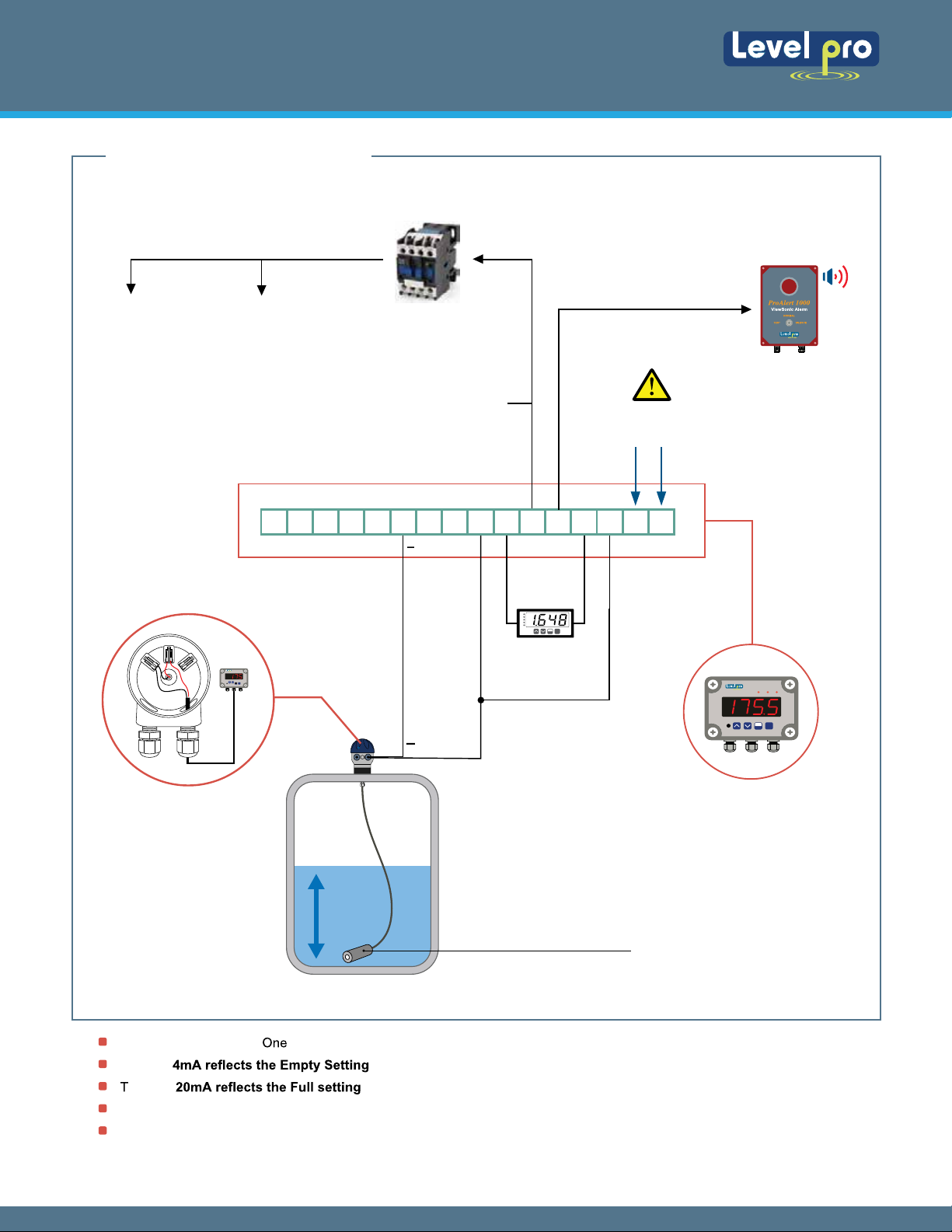
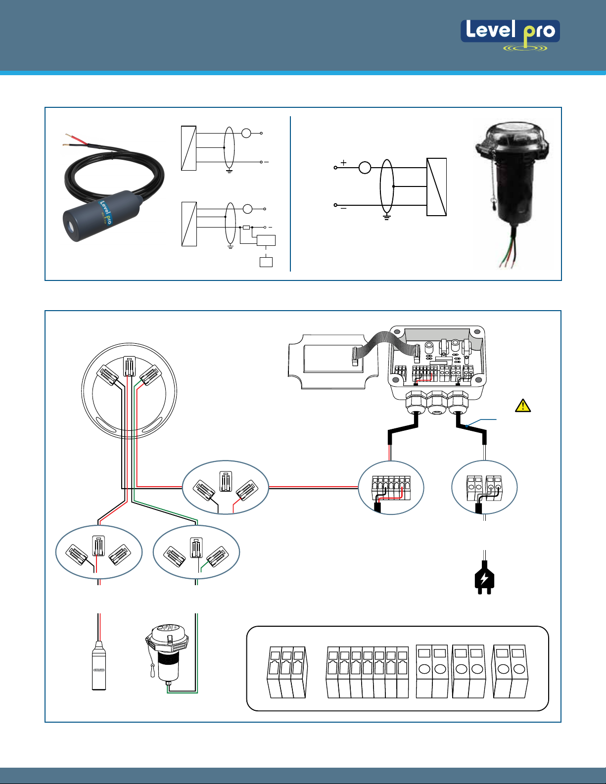
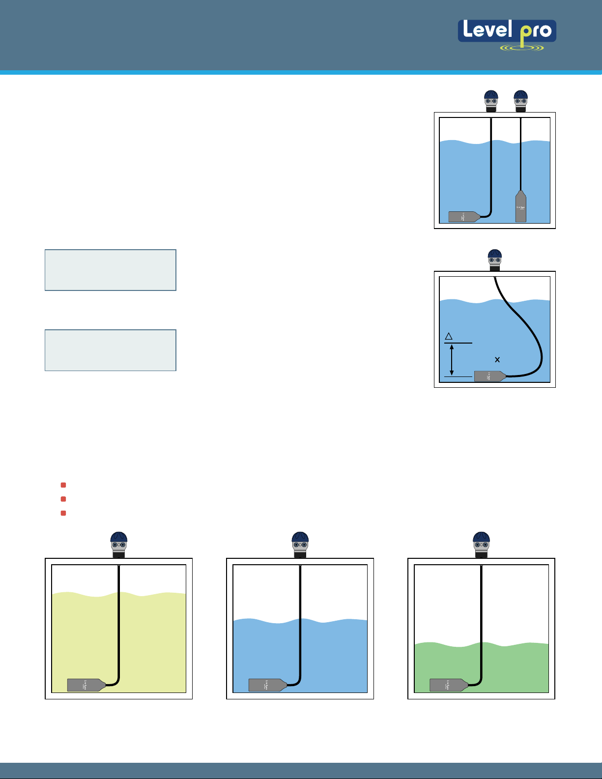
The Levelpro pressure transmitter is placed near or on the bottom of the tank. A ceramic pressure diaphragm within the pressure
transmitter is exposed on one side to the application liquid. The other side is exposed to the reference pressure via a small ventilation
tube located inside of the cable. The difference in pressure between liquid and reference pressures will slightly deflect the diaphragm.
The deflection of the diaphragm is measure by a built-in microprocessor located inside the ceramic diaphragm.which is converted into a
4-20mA two wire current signal proportional the height of the liquid. Make sure that Levelpro Transmitter is compatible with the
application liquid media.
TECHNOLOGY
SAFETY PRECAUTIONS
About this Manual : PLEASE READ THE ENTIRE MANUAL PRIOR TO INSTALLING OR USING THIS PRODUCT. This
manual includes information on all versions of the Levelpro Pressure Level Transmitters Please refer to the part number
located on the transmitter label to verify the exact model which you have purchased.
User's Responsibility for Safety : Levelpro offers a wide range of liquid level sensors and technologies. While each of
these technologies are designed to operate in a wide variety of applications, it is the user's responsibility to select a
technology that is appropriate for the application, install it properly, perform tests of the installed system, and maintain all
components. The failure to do so could result in property damage or serious injury.
Proper Installation and Handling : Only properly-trained staff should install and/or repair this product.
Wiring and Electrical : CAUTION - Do not exceed specified supply voltage rating of 30 VDC. Permanent damage not
covered by warranty will result. This device is not designed for 120 or 240 volt AC operation. Use only the specified
voltage found in the specification sections.
Temperature and Pressure : TheLevelpro series are designed for use in the specified application temperatures referred
to in the specification section.
Material Compatibility : Make sure that the model which you have selected is chemically compatible with the application
liquids.
Make a Fail-Safe System : Design a fail-safe system that accommodates the possibility of transmitter failure or battery
power loss. In critical applications, Levelprorecommends the use of redundant backup systems and alarms in addition to
the primary system.
If the device came in contact with hazardous substances, certain precautions have to be complied with for purification!
The device must be disposed according to the European Directives 2002/96/EG and 2003/108/EG (on waste electrical and
electronic equipment) Waste of electrical and electronic equipment may not be disposed by domestic refuse!
6. DISPOSAL
WARNING!Depending on the measuring medium, deposit on the device may cause danger for the user and
the environment. Comply with adequate precau-tions for purification and dispose of it properly.
ContinuousSubmersibleLevel Transmitter
Levelpro-Sensors Manual
06
© Icon Process Controls Ltd. All Rights Reserved

8. GETTING STARTED
Pressure transmitters are designed to be completely submersed within the application fluid. The
transmitters can either rest along the bottom of the tank or be suspended at any desired level
within the tank. Please note that the physical location of the level transmitter will indicate the
lowest level of measurement within the tank.
For example: mounting the transmitter 2 feet from the bottom of the tank, then the lowest reading
of liquid will be 2 feet from the bottom.
The Specific Gravity (SG) of a liquid will not change the pressure of the transmitter, but will affect how the transmitter reads the liquid
height. Remember, liquids with a SG < 1.0 are lighter than water (Oil) and liquids with a SG > 1.0 are heavier than water. (Sulphuric Acid)
GETTING STARTED (Continued)
How does Specified Gravity affect pressure transmitters?
How to convert Pressure into Liquid Height?
Pressure transmitters are all defined by the pressure range or distance range. To convert pressure
to Liquid Height, use the following ratio:
1 psi = 2.31 feet of water
or
1 psi = 0.704 meters of water
10 psi x 2.31'/psi = 23.1'
or
23.1'/2.31 = 10 psi
Therefore, a 10 psi transmitter will have a
Liquid Height = 23.1 feet
With the above ratio, you can always find the Liquid Height or Water Column (wc) of any Levelpro
pressure transmitter
SG = .0 (Water H20) SG = 1.2SG = 0.9
1 psi
2.31 Feet (S.G.)
H2
Water has a SG = 1.0.
A SG <1.0 required more liquid (a taller water column) to equal the same pressure or height as with water.
A SG >1.0 requires less liquid (shorter water column) to equal the same pressure or height as with water.
ContinuousSubmersibleLevel Transmitter
Levelpro-Sensors Manual
07
© Icon Process Controls Ltd. All Rights Reserved

Levelpro sensors are provided in distance measurement ranges i.e. 0-14 ft, 0-20 ft, 0-33 ft etc. To calculate the maximum range or the
liquid that a particular sensor will measure, use the following formula:
Example : 0-14 ft transmitter installed in a liquid with a maximum height of 12 feet and a SG=0.9 will have a Sensor Height with a
range 0-14' = 14 feet /0.9 = 15.5'…so it can measure more liquid than the 14' range due to the SG being below 1 (H20 water)
Example : Compare the Maximum Liquid Height of a liquid with a SG = 1.5.
SG = 1.5 : 0-20' Range transmitter will have a Maximum Sensing Height (Liquid) = 20/1.5 = 15 ft
SG = 1.0 : 0-20' Range transmitter will have a Maximum Sensing Height (Liquid) = 20/1 =20 ft
When the Specific Gravity is less than 1.0, the Maximum Liquid Height of the transmitter will increase. The reverse is true by increasing
the Specific Gravity. With a SG = 1.5, the Maximum Sensing Height (Liquid) = 15' with a Transmitter with a Range of 0-20 ft
Transmitter
Note :Identifying the correct specific gravity for the fluid is critical in understanding the operational range of the pressure transmitter.
Maximum Liquid Height (feet) = Maximum Liquid Height of Liquid / SG
This method works with the Levelpro Series level displays & controllers. These panel meters are configured using the linear SCALE
function. The settings are as follows:
GETTING STARTED (Continued)
Settings Default Represents Typical Setting
Input 1= Empty 4.0 Input Current @ Empty 4.0mA
Input 2 = Full 20.0 Input Current @ Full 20.0mA
How to configure a panel meter when a pressure transmitter is used?
Remember, pressure transmitters are configured so 0 psi/ft = 4 mA and the maximum psi/ft = 20 mA. Levelpro pressure transmitter
applications will not use the full range of the transmitter. Therefore, a full tank will typically have a current less than 20 mA.
Note: The values for empty and full represent what the display will show when the tank is either Empty or Full. Empty and Full
must be the same units (example: Gallons, Inches, percent).
9. INSTALLATION
The Levelpro Series is designed to operate while submerged in the actual application liquid. Avoid
installing the level transmitter along the bottom of the tank if materials such as sludge will build up
and coat/cover the transmitter. This also includes any debris that will settle along the bottom of the
tank. In these applications, it is best to suspend the transmitter above the highest level of
sludge/debris that will occur.
Location : Select a location where the temperature of the transmitter will be within the
specification of the sensor.
Position : The transmitter is not position sensitive.
Mounting : The transmitter can be mounted via several methods. It can be suspended
from the cable, it can be placed resting on the bottom of the tank in either horizontal or
vertical orientation, or it can be attached to a pipe or hardwired using the LP100 conduit
box on the top of the housing.
1.
2.
3.
SLUDGE
ContinuousSubmersibleLevel Transmitter
Levelpro-Sensors Manual
08
© Icon Process Controls Ltd. All Rights Reserved

2 4 . 0V
+
-
24VDC POWER SUPPLY
DIGITAL MULTIMETER
100 SERIES SENSORS
Note: Use caution when sealing the cable at the top of the tank. There is a
ventilation/reference tube located within the cable. The purpose of this tube is
provide a comparison between atmospheric pressure and the pressure that is being
exerted on the sensing diaphragm within the tank. The reference tube must be open
and free to allow air to flow back to the pressure diaphragm. Avoid blocking or
bending the ventilation tube by compressing the cable. Always keep the cable
termination clean, dry and free of moisture and prevent liquid from entering the vent
tube. The LP100 Installation Junction Box comes with a Gortex breather to allow for
air to pass but not moisture. It also has the cable grip located at the bottom to
secure the sensor.
Avoid installations where other tank requirements will cause the transmitter to move or swing.
Example: A mixer blade could cause the level transmitter to whip around within the tank. An
alternative would be to move the transmitter to a more stable section of the tank or to install the
Transmitter inside a still well/drop tube. This will minimize the effects created by the mixer.
Termination: The cable for the transmitter is typically terminated at a junction box located on top of
the tank. Since the vent tube is contained within the cable, the pressure within the junction box
must always be the same as the reference (typically atmospheric) pressure for the liquid. The
inside of the function box must be clean, dry and free of moisture. (A descant can be provided)
Add the optional fitting LP 100 to complete the package. The LP 100 features a 2" NPT thread for
mounting and a liquid tight connector to seal the cable interface, and a Gortex breather that allows
for the transfer of air, but not moisture.
After final installation of the Levelpro transmitter and its companion receiver (TruVu), no routine maintenance is required. A periodic check
of system calibration is suggested. Be sure to include a brief description of the problem plus any relevant application notes. Contact
customer service to receive a return goods authorization number before shipping.
Maintenance should consist of inspection to see that the transmitter is free from debris and not coated with any substance, which would
prevent liquid from freely entering and leaving the transmitter. If this occurs, the transmitter should be cleaned.
If transmitter is not functioning properly, isolate the transmitter from
the system and wire as shown below. Be sure to remove the sensor
from the classified area when preforming this test. Multi - Meter
should read 4mA with the transmitter out of liquid.
1. First, verify that the sensor is wired correctly.
2. Next, check if the power supply is providing the required power.
3. Finally confirm that the loop resistance is not exceeding the sensor's specification.
10. MAINTENANCE
Testing the Transmitter:
200
2000k
200k
E
B
CC
B
E
E
NPN
PNP
E
20k
2000 200
hFE
2000
20
200 200
750
200
2000
20
200
1000
m
m
V
V~
10A
OFF
4.0
24V
4mA
4-20mA Output
Cable Grip
Gortex Breather
ContinuousSubmersibleLevel Transmitter
Levelpro-Sensors Manual
09
Vaporbloc ®
Com
mA

Icon Process Controls warrants to the original purchaser of its products that such products will be free from defects in materials and
workmanship under normal use and service in accordance with instructions furnished by Icon Process Controls for a period of one years
from the date of sale of such products. Icon Process Controls obligation under this warranty is solely and exclusively limited to the
repair or replacement, at Icon's option, of the products or components, which Icon examination determines to its satisfaction to be
defective in material or workmanship within the warranty period.
Icon Process Controls must be notified within thirty (30) days pursuant to the instructions below of any claims of lack of conformity
under this warranty . Any product repaired under this warranty will be warranted only for the remainder of the original warranty period.
Any product provided as a replacement under this warranty will be warranted for the full 1 year from the data of sale.
Products cannot be returned to Icon Process Controls without Icon's prior authorization. To return a product that is thought to be
defective please submit a customer return (MRA) request form and follow the instructions therein. All warranty and non-warranty product
returns to Icon Process Controls must be shipped prepaid and insured. Icon will not be responsible for any products lost or damaged in
shipment.
For technical support please contact us at [email protected] | visit www.iconprocon.com |905.469.9283
Please ensure you have the Part and Serial number available
11. WARRANTY, RETURNS & LIMITATIONS
Returns:
Limitations:
This warranty does not apply to products which :
1)
are beyond the warranty period or are products for which the original purchaser does not follow the warranty procedures outlined above;
2) have been subjected to electrical, mechanical or chemical damage due to improper, accidental or negligent use;
3) have been modified or altered;
4) anyone other than service personnel authorized by Icon have attempted to repair;
5) have been involved in accidents or natural disasters; or
6) are damaged during return shipment to Icon.
Icon Process Controls reserves the right to unilaterally waive this warranty and dispose of any product returned to Icon where :
1) there is evidence of a potentially hazardous material present with the product; or
2) the product has remained unclaimed at Levelpro for more than 30 days after Icon Process Controls has dutifully requested disposition.
This warranty contains the sole express warranty made by Levelpro in connection with its products. ALL IMPLIED WARRANTIES,
INCLUDING WITHOUT LIMITATION, THE WARRANTIES OF MERCHANTABILITY AND FITNESS FOR A PARTICULAR PURPOSE,
ARE EXPRESSLY DISCLAIMED. The remedies of repair or replacement as stated above are the exclusive remedies for the breach of
this warranty. IN NO EVENT SHALL LEVELPRO BE LIABLE FOR ANY INCIDENTAL OR CONSEQUENTIAL DAMAGES OF ANY KIND
INCLUDING PERSONAL OR REAL PROPERTY OF FOR INJURY TO ANY PERSON. THIS WARRANTY CONSTITURES THE FINAL,
COMPLETE AND EXCLUSIVE STATEMENT OF
WARRANTY TERMS AND NO PERSON IS AUTHORIZED TO MAKE ANY OTHER WARRANTIES OR REPRESENTATIONS ON
BEHALF OF Icon Process Controls.
ContinuousSubmersibleLevel Transmitter
Levelpro-Sensors Manual
10

ContinuousSubmersibleLevel Transmitter
Levelpro-Sensors Manual
Table of contents
Other Level Pro Accessories manuals
Popular Accessories manuals by other brands

Fozmula
Fozmula L13X Calibration instructions

Trio Datacom
Trio Datacom EB450 quick start guide

Parker Pneumatic
Parker Pneumatic MPS-1 Series Installation & service instructions

Philips
Philips CRP323 brochure

Lightolier
Lightolier Lytespan 24MHT4RS specification

Banner
Banner Registration Mark Sensor R58 Expert brochure

HBM
HBM T10FM Mounting instructions

KAPSULE
KAPSULE UV-C SANITIZER manual

HomeMatic
HomeMatic HM-WDS100-C6-O-2 Mounting instruction and operating manual

Crestron
Crestron AirBoard CCS-WB-1 Supplemental guide

Cardinal
Cardinal 205 Installation and technical manual

SKY-WATCHER
SKY-WATCHER Star Adventurer 2i instruction manual