SAFETY PRECAUTIONS
About this Manual : PLEASE READ THE ENTIRE MANUAL PRIOR TO INSTALLING OR
USING THIS PRODUCT. This manual includes information on all versions of the Levelpro
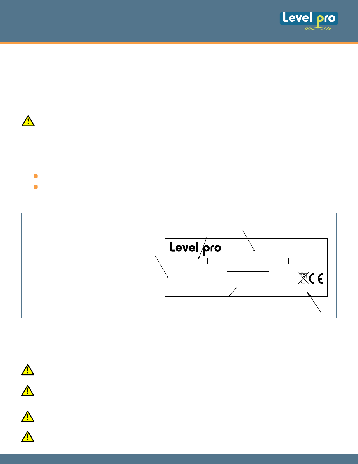
Pressure Level Transmitters Please refer to the part number located on the transmitter label to
verify the exact model which you have purchased.
User's Responsibility for Safety : Levelpro offers a wide range of liquid level sensors and
technologies. While each of these technologies are designed to operate in a wide variety of
applications, it is the user's responsibility to select a technology that is appropriate for the
application, install it properly, perform tests of the installed system, and maintain all
components. The failure to do so could result in property damage or serious injury.
Proper Installation and Handling : Only properly-trained staff should install and/or repair this
product.
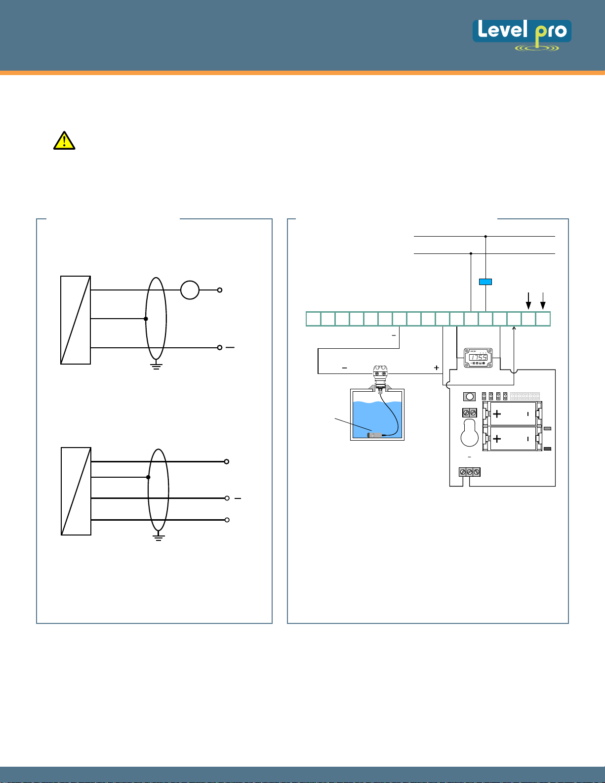
Wiring and Electrical : CAUTION - Do not exceed specified supply voltage rating of 30 VDC.
Permanent damage not covered by warranty will result. This device is not designed for 120
or 240 volt AC operation. Use only the specified voltage found in the specification sections.
Temperature and Pressure : The Levelpro series are designed for use in the specified
application temperatures referred to in the specification section.
Material Compatibility : Make sure that the model which you have selected is chemically
compatible with the application liquids.
Make a Fail-Safe System : Design a fail-safe system that accommodates the possibility of
transmitter failure or battery power loss. In critical applications, Levelpro recommends the use
of redundant backup systems and alarms in addition to the primary system.
Heavy Duty Industrial Level Transmitter
Levelpro-Sensors Manual
8
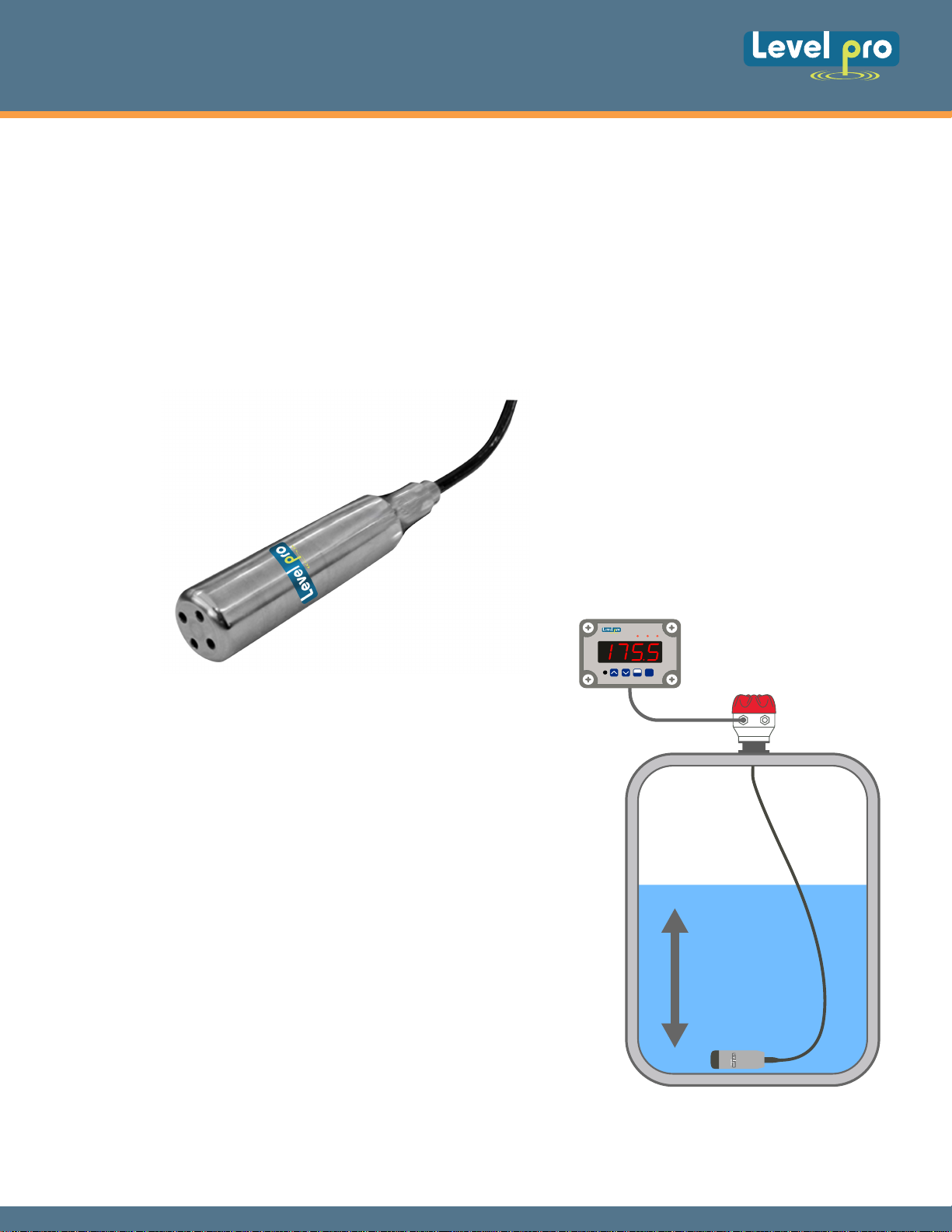
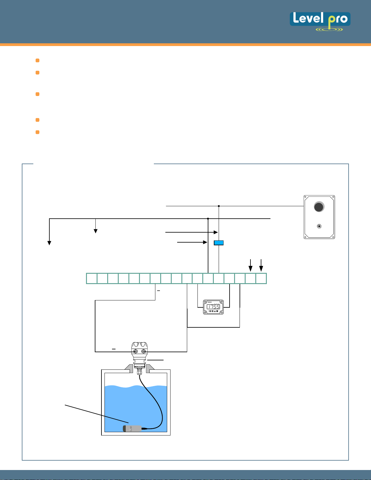
GETTING STARTED
Pressure transmitters are designed to be completely
submersed within the application fluid. The transmitters
can either rest along the bottom of the tank or be
suspended at any desired level within the tank. Please
note that the physical location of the level transmitter
will indicate the lowest level of measurement within the
tank. For example: mounting the transmitter 2 feet from
the bottom of the tank, then the lowest reading of liquid
will be 2 feet from the bottom.