manuals.online logo
Brands
  1. Home
  2. •
  3. Brands
  4. •
  5. IntelliSense
  6. •
  7. Accessories
  8. •
  9. IntelliSense PHANTOM XJ-835 User manual

IntelliSense PHANTOM XJ-835 User manual

35' x 50'
(11 m x 15 m)
Range
INSTALLATION INSTRUCTIONS
PHANTOM
FEATURES
.35' x 50' range Form A alarm relay
.
.RF immunity
.SelectablePIRsensitivity
.Flush-mount installation
Mirrored optics
Built-in range adjustment
.
Electronic circuit protection
.
MOUNTING LOCATION
The XJ-835 is designed for useindoors. Make sure the sensor has a clear
line of sight to the protected area. Infrared energy cannot penetrate solid
objects. If the XJ-835 is blocked, it will not alarm.
Aim the XJ-835 toward the interior of the room, away from windows and
heating/cooling sources.
Amountingtemplateisprovided for easy installation. Tracethetemplateon
the mounting surface, then cut and drill the holes. Follow the instructions in
the Mounting Procedure section to mount the sensor.
The unit can also be installed in a single-gang electrical box. Follow the
installation procedure described in the Mounting Procedure section.
MOUNTING PROCEDURE (Continued)
2. Remove the printed circuit board (PCB) by pushing the board in and
down(atthesametime). Whentheboardisclearoftheenclosure,gently
pull it from the housing. Refer to Figure 1.
3. Secure the rear housing to the desired location with either two or four #6
slotted countersunk flathead screws. (Make sure the rear housing is
mounted upright as shown in Figure 2.)
4. Wire the unit (refer to the Wiring section), and return the PCB to the rear
housing.
5. Place the two rectangular labels (provided) over the mounting holes as
shown in Figure 2.
6. Toreplacethefronthousing:place the insidefronthousing slots overthe
top latches of the rear housing and snap the housings together. (Refer
to Figure 2.)
Model XJ-835
PassiveInfrared
MotionSensor
The XJ-835 flush-mount passive infrared motion sensor from IntelliSense
provides reliable detection coverage at an affordable price.
TheXJ-835featuresadense35'x50'pattern,RFimmunity,andalow20mA
current draw. In addition, an adjustable printed circuit board (PCB) makes
it possible to adjust the range without relocating the sensor.
This compact, attractive unit is easy to install and maintain. A mounting
template is included with the XJ-835 to simplify installation.
APPLICATIONS
The XJ-835 is ideal for office and residential applications.
MOUNTING PROCEDURE
To mount the unit:
1. Remove the front
housing from the unit
by depressing the
latch through the
slot in the bottom of
theXJ-835,while
separating the front
and rear housings.
.
DualelementPIR
.
.Dense detection pattern
.Pet-alley mask included
.
.9 - 14 VDC operation
Low 20 mA current draw at
12VDC
NOTE: When
using the pet-
alleymask,mount
the sensor at a
height of 3' 4"
and set the PCB
at position +1.
Figure4
XJ-835PIR
MIRROR
PET-ALLEYMASK
The pet-alley mask blocks lower zones
to exclude small pets from the field of view.
To install the pet-alley mask:
1. Remove the PCB from the rear
housing.
2. Install the masking material
(provided) over the two lower
and four intermediate PIR
mirror segments.
(See Figure 4.)
3. Return the PCB to the rear
housing and walk-test the unit.
Figure1 XJ-835Assembly
Push PCB here to
remove from rear
housing
PCB
PCB
Holder
Slot
Depress latch to
remove front housing
Front Housing
Rear Housing
Top latches
PCB
Enclosure Place the pet-
alley mask
over these
segments of
thePIR mirror
RANGE ADJUSTMENT
The XJ-835 housing is designed for easy PCB adjustment. This allows for
detection range adjustment without relocating the sensor.
PCB POSITION
3'4"
6'
8'
10'
35' 30' 25'
35' 30'
+10-1-2-3
MTG
HEIGHT
35'
25'35'
15'
XJ-835RangeChart
****
***
* * 20'
*
*PCB Positions not recommended.
Press the PCB in and move it up or down until it "clicks" into the desired
PCB position. (Refer to Figure 2.)
Walk-testthesensor.
Referto theXJ-835 Range Chart
on the right.
At the left side of the chart, find
the desired mounting height.
On the top of the chart, find the
required PCB position.
The square where PCB position
and mounting height intersect is
the pattern distance.
.
.
.
.
.
.
To adjust the range:
WIRING
Terminal strip TB1 is located at
the back edge of the PCB.
The XJ-835 rear housing features
a convenient PCB holder for
wiring. Remove the PCB from the
rear housing and slide it into the
PCB holder (refer to Figure 2).
Wire the XJ-835 as shown in
Figure 3 (use 22 to 14 AWG).
Figure 2 Rear Housing
Top latches
PCB
Holder
Depress
this latch
to remove
the front housing PCB
Positions
Labels
covering
mounting
holes
Figure3
Wiring
NC C
100 mA,
30VDC
ALARM
20 mA,
9 - 14 VDC
POWER
+
TM
5-051-259-00 Rev D
IntelliSense is a trademark of IntelliSense Systems, Inc.
Patented. Other US and International Patents Applied
For. Copyright 1995 IntelliSense
All rights reserved.
PIR SENSITIVITY PROTECTION PATTERNS
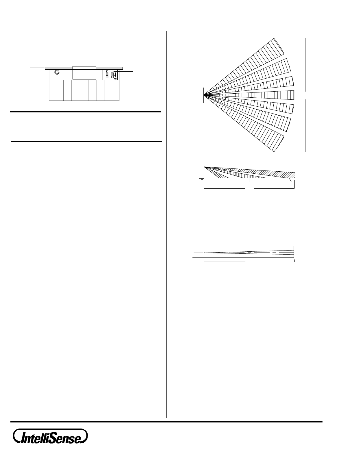
TOPVIEW
Wide Angle Pattern
Seller warrants its products to be in accordance with its own plans and specifications and to be free
fromdefectsinmaterialsandworkmanshipundernormaluseandservicefor18monthsfromthedate
stamp control on the product; or for products not having an IntelliSense Systems date stamp, for 12
months fromthe dateof original purchase,unless theinstallation instructions orcatalogue sets forth
a shorter period, in which case the shorter period shall apply.
Seller's obligation shall be limited to repairing or replacing, at its option, free of charge for materials
or labor, any part which is proved not in compliance with Seller's specifications or proves defective
in materials or workmanship under normal use and service. This warranty is void if the product is
altered or improperly repaired or serviced by anyone other than an authorized IntelliSense factory
service center. Contact your local IntelliSense distributor for the service center location nearest you.
THEREARENOWARRANTIES,EXPRESSORIMPLIED,OFMERCHANTABILITY,ORFITNESSFOR
APARTICULARPURPOSE OROTHERWISE,WHICHEXTENDBEYONDTHEDESCRIPTION ON
THE FACE HEREOF. In no case shall Seller be liable to anyone for any consequential or incidental
damages for breach of this or any other warranty, express or implied, or upon any other basis of
liability whatsoever, even if the loss or damage is caused by Seller's own negligence or fault.
Seller does not represent that its product may not be compromised or circumvented; that the product
will prevent any personal injury or property loss by burglary, robbery, fire, or otherwise; or that the
product will in all cases provide adequate warning or protection. Buyer understands that a properly
installed and maintained alarm system may only reduce the risk of burglary, robbery, or fire without
warning, but it is not insurance or guarantee that such will not occur or that there will be no personal
injuryorpropertylossasaresult. CONSEQUENTLY,SELLERSHALLHAVENOLIABILITYFORANY
PERSONAL INJURY, PROPERTY DAMAGE, OR OTHER LOSS BASED ON A CLAIM THAT THE
PRODUCT FAILED TO GIVE WARNING. However, if Seller be held liable, whether directly or
indirectly, for any loss or damage arising under this Limited Warranty or otherwise, regardless of
cause or origin, Seller's maximum liability shall not in any case exceed the purchase price of the
product, which shall be fixed as liquidated damages and not as a penalty, and shall be the complete
and exclusive remedy against Seller.
This warranty replaces all previous warranties and is the only warranty made by IntelliSense on this
product. No increase or alteration, written or verbal, of the obligation of this warranty is authorized.
LIMITEDWARRANTY
TheXJ-835 is equippedwith adip switch forselecting PIRsensitivity. Refer
to the chart below to determine which sensitivity level is best suited for your
application.
SENSITIVITY DIP SWITCH #1
Figure5 SettingthePIRSensitivity
WALK-TEST
Apply power to the unit and let it warm up for at least three minutes. Begin
walk-testing when the alarm LED (DS1) goes out.
Walk across the protected area at the ranges to be covered. Two to four
normal steps across the pattern should make the alarm LED light. Wait for
thealarmLEDtogoout,thencontinuewalk-testing. Whenthereisnomotion
in the protected area, the alarm LED should be off.
Important: The XJ-835 should be tested at least once each year to
ensure proper operation.
ALARMLEDDISABLE
To disable the alarm LED (DS1) after walk-testing the sensor, move
DIP Switch #2 to the OFF position. See Figure 5.
OFF
LOW
(Pulse count 3)
ONHIGH
(Pulse count 2)
PCB DIP
SWITCH
#1
ALARMLED
(DS1)
35'
SIDEVIEW
Wide Angle Pattern
ZONES
floor
TOPVIEW
Pet-Alley Pattern The TOP VIEW Pet-Alley Pattern is the
same as the TOP VIEW Wide Angle
Pattern.
SIDEVIEW
Pet-Alley Pattern
Intermediate
8'
Long RangeLower 35'
3'4"
50'
Important: The XJ-835 must be connected to a UL listed power
supply or UL listed control panel capable of providing a minimum
of four hours of standby power.
SPECIFICATIONS
Range:
35'x50'
(11 m x 15 m)
PIRfieldsofview:
7 long range zones
4 intermediate
2 lower
Alarmrelay:
Form A (normally closed)
100mA,30VDC
Powerrequirements:
9-14VDC
20mA,12VDC
RFimmunity:
30 V/m, all mobile bands
10 - 1000 MHz
PIRsensitivity:
DIP switch selectable pulse count;
pulse count 2 (high) or pulse
count 3 (low)
Dimensions:
4.5" high x 2.9" wide x 2.5" deep
(11.4 cm x 7.4 cm x 6.4 cm)
Weight:
3 oz (84 g)
Packaged Product is 6 oz (170 g)
Approvals/Listings:
UL listed
Whitelightimmunity:
up to 20,000 candlepower at 10'
(3 m)
Operatingtemperature:
32oto 120oF (0oto 49oC)
TM

Other IntelliSense Accessories manuals

IntelliSense DUAL TEC DT-900 Series Owner's manual

IntelliSense

IntelliSense DUAL TEC DT-900 Series Owner's manual

IntelliSense DT-7225 User manual

IntelliSense

IntelliSense DT-7225 User manual

IntelliSense DT-420T User manual

IntelliSense

IntelliSense DT-420T User manual

IntelliSense DT-725D DUAL TEC User manual

IntelliSense

IntelliSense DT-725D DUAL TEC User manual

IntelliSense IS-2260 Service manual

IntelliSense

IntelliSense IS-2260 Service manual

IntelliSense DT-7435 EU DUAL TEC Setup guide

IntelliSense

IntelliSense DT-7435 EU DUAL TEC Setup guide

IntelliSense DT-600 Series User manual

IntelliSense

IntelliSense DT-600 Series User manual

IntelliSense DT-7450 EU DUAL TEC Setup guide

IntelliSense

IntelliSense DT-7450 EU DUAL TEC Setup guide

IntelliSense IntelliSense IS-320 User manual

IntelliSense

IntelliSense IntelliSense IS-320 User manual

IntelliSense MC-550 User manual

IntelliSense

IntelliSense MC-550 User manual

IntelliSense DT-700 DUAL TEC User manual

IntelliSense

IntelliSense DT-700 DUAL TEC User manual

IntelliSense STEALTH XJ-2035 User manual

IntelliSense

IntelliSense STEALTH XJ-2035 User manual

Popular Accessories manuals by other brands

Quincy lab 140AE-1 operating manual

Quincy lab

Quincy lab 140AE-1 operating manual

HomePro ZIR000 user manual

HomePro

HomePro ZIR000 user manual

DOL 20SCR Technical user guide

DOL

DOL 20SCR Technical user guide

RAB Smart Task installation manual

RAB

RAB Smart Task installation manual

Kemppi KMS 300 quick guide

Kemppi

Kemppi KMS 300 quick guide

Stearns 57,500 Series Installation and service instructions

Stearns

Stearns 57,500 Series Installation and service instructions

iGuzzini TWILIGHT COPENAGHEN manual

iGuzzini

iGuzzini TWILIGHT COPENAGHEN manual

Adelaide Annexe & Canvas Avan Deluxe installation guide

Adelaide Annexe & Canvas

Adelaide Annexe & Canvas Avan Deluxe installation guide

OHAUS 5000 instruction manual

OHAUS

OHAUS 5000 instruction manual

HOME8 WLS1300 quick start guide

HOME8

HOME8 WLS1300 quick start guide

MAXBOTIX MaxSonar quick start guide

MAXBOTIX

MAXBOTIX MaxSonar quick start guide

ioSmart iSmart56 Installation and user guide

ioSmart

ioSmart iSmart56 Installation and user guide

Focusrite Scarlett 18i8 user guide

Focusrite

Focusrite Scarlett 18i8 user guide

Velleman ED38105 user manual

Velleman

Velleman ED38105 user manual

JumpSport SkyBounce user manual

JumpSport

JumpSport SkyBounce user manual

Prima-Temp PRIYA Instructions for use

Prima-Temp

Prima-Temp PRIYA Instructions for use

Tefcold BC85I-BC85I W user manual

Tefcold

Tefcold BC85I-BC85I W user manual

Vaisala WMS302 user guide

Vaisala

Vaisala WMS302 user guide

manuals.online logo
manuals.online logoBrands
  • About & Mission
  • Contact us
  • Privacy Policy
  • Terms and Conditions

Copyright 2025 Manuals.Online. All Rights Reserved.