LevelGuard Z24802PTZ User manual

WARNING!
Read this Operator’s
Manual carefully prior to using this
device. Failure to understand and
follow the contents of this manual
may result in electrical shock, fire
and/or serious personal injury.
Table of Contents
What is the LevelGuard™Sump Pump Control?...2
Features.........................................................2
Will it work with my pump?...........................3
Important Safety Information..................... 4-5
Installation Instructions.................................6
Remove Existing Switch.................................7
Install LevelGuard Sump Pump Control..........8
Electrical Connection.....................................9
Test..............................................................10
Trouble-Shooting.........................................11
Maintenance Guide......................................12
Service & Repair..........................................12
5-Year Limited Warranty..............................12
INSTALLATION INSTRUCTIONS
Sump Pump Control with 8 ft. cord
Model Z24802PTZ SKU# SUMP-RES5

2 | Sump Pump Control System
What is the LevelGuard™ Sump Pump Control?
LevelGuard™Sump Pump Control uses patented “Field-Effect” sensing technology to reliably detect water
level and solid-state digital switching to replace conventional pump switches, completely eliminating the
#1 failure mode in traditional sump pump systems.
Features
•
Uses patented “Field-Effect” sensing technology to detect water level through the water-tight thermoplastic shell.
• NO MOVING PARTS to wear out or bind.
• Includes fused over-current protection against pump electrical failures.
• Requires less working space than mechanical float switches.
• Reliably controls a 6.7" (170mm) water column.
• Automatic time-delay before turn-on minimizes activation from water sloshing and extends pump life.
• Tested to 1.5 million cycles — outlasts traditional float switches 7 to 1.
• Simple piggyback plug electrical installation — easy replacement for old system.
• RoHS Compliant, UL-Listed.
GFCI
Protected
Outlet
6" Fluid Level
Control Range
“SWITCH OFF”Level
“SWITCH ON”Level

www.LevelGuardProducts.com | 3
Will it work with my pump?
• LevelGuard™Sump Pump Control replaces mechanical float-switches on new and existing sump pumps.
• The Sump Pump Control is designed to work with piggyback-plug style electrical systems ONLY.
•
DO NOT use LevelGuard Sump Pump Controls in systems where the switch is directly integrated into the pump.
NOTICE: Since the LevelGuard Sump Pump Control works in combination with an existing pump,
you must read and follow the Manufacturer’s instructions for that pump. Failure to do so may void the
warranty or cause product damage.
Piggyback-Plug
System
Integrated Switch
Pump Systems
YES
NO!

4 | Sump Pump Control System
Important Safety Information
SAVE THESE INSTRUCTIONS
Carefully read this manual before installing or using this product. Failure to understand and follow this
manual may result in personal injury, electrical shock, and/or fire.
SAFETY SYMBOLS & SIGNAL WORDS
Read and Understand these types of Warnings:
DANGER: means that someone will be injured or killed if the safety information is not followed.
WARNING: means that someone could be injured or killed if the safety information is not followed.
NOTICE: means that property or equipment damage may result if instructions are not followed.
Personal Safety
DANGER: This installation involves use of high-voltage electricity in a wet environment, so please use
common sense and caution.
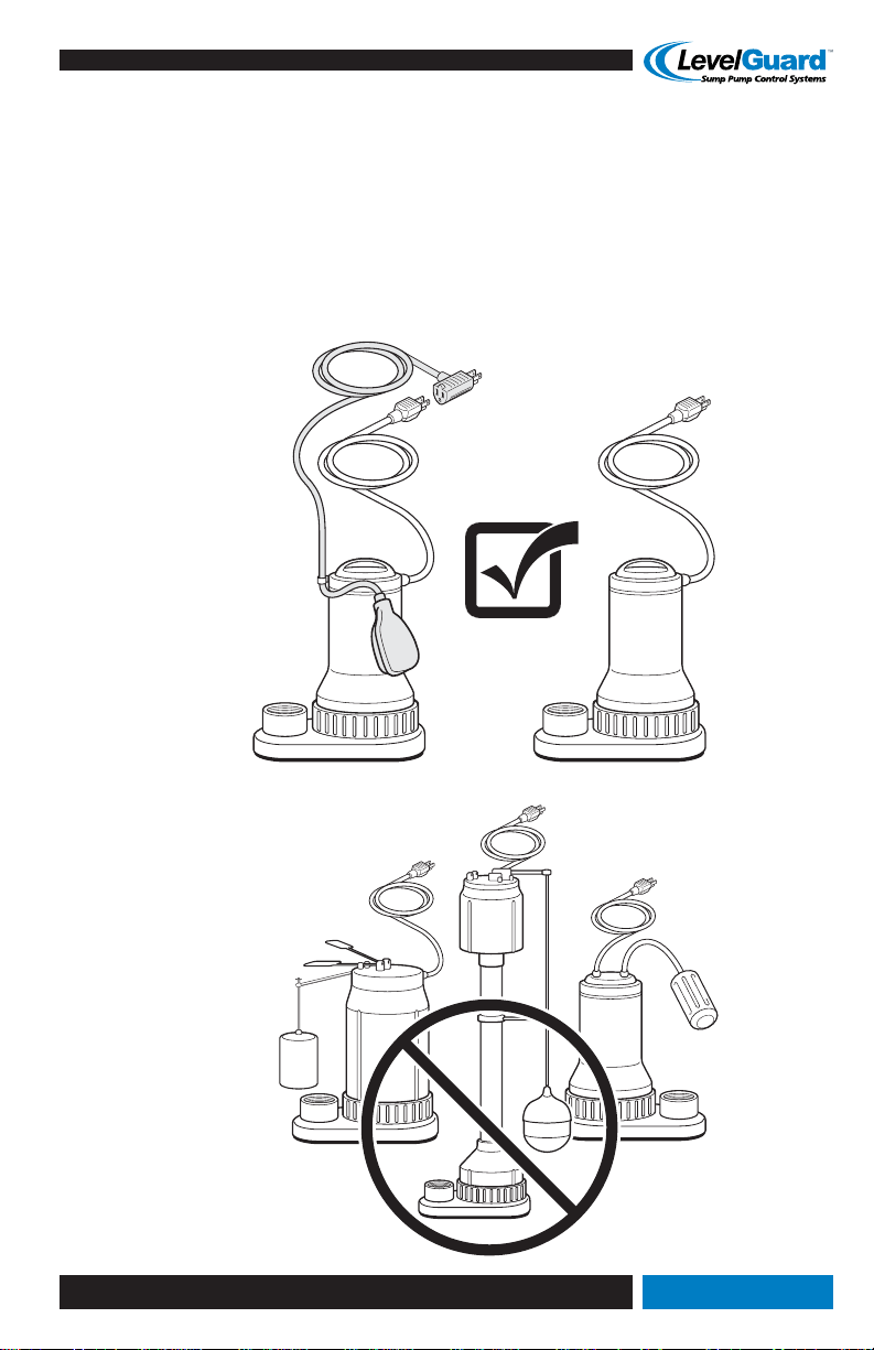
You can safely install the LevelGuard™Sump Pump Control ONLY IF YOU:
• Contact a qualified electrician immediately if sump area is wet or flooded. Do not walk on or touch
wet areas until all power is disconnected from pump electrical outlet.
• DO NOT touch the sump pump or discharge piping when the pump is connected to electrical
power and water is present in the sump pit. Always disconnect the pump from the power source
before handling.
• Do not install this product while impaired in any way.
• Do not allow by-standers, children, or pets to come near the installation or cause distraction.
• Keep loose clothing and jewelry away from electrical parts. Use non-skid shoes and proper
eye protection.
• Do not operate this electrical device in an explosive atmosphere, such as in the presence of
flammable liquids, gases, or dust. The LevelGuard Sump Pump Control is sealed and solid-state, but
the pump motor can create sparks that may ignite dust or fumes.
Equipment and Electrical Safety
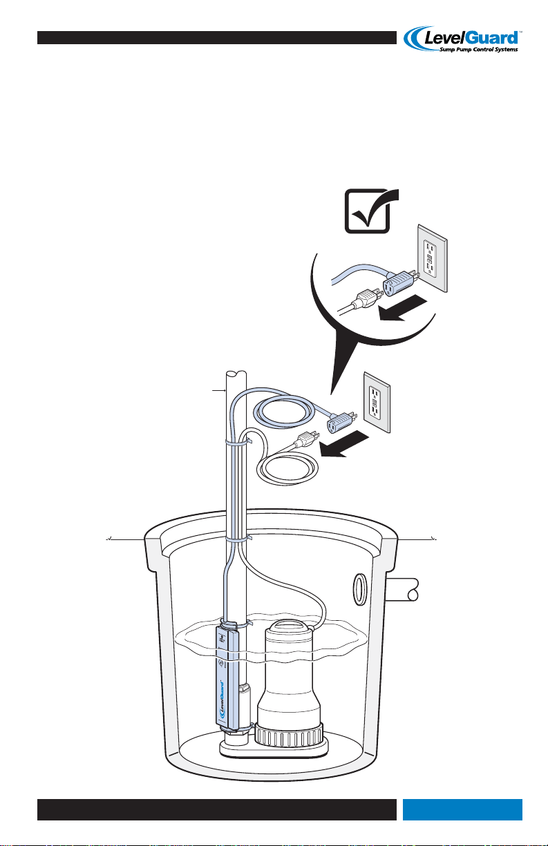
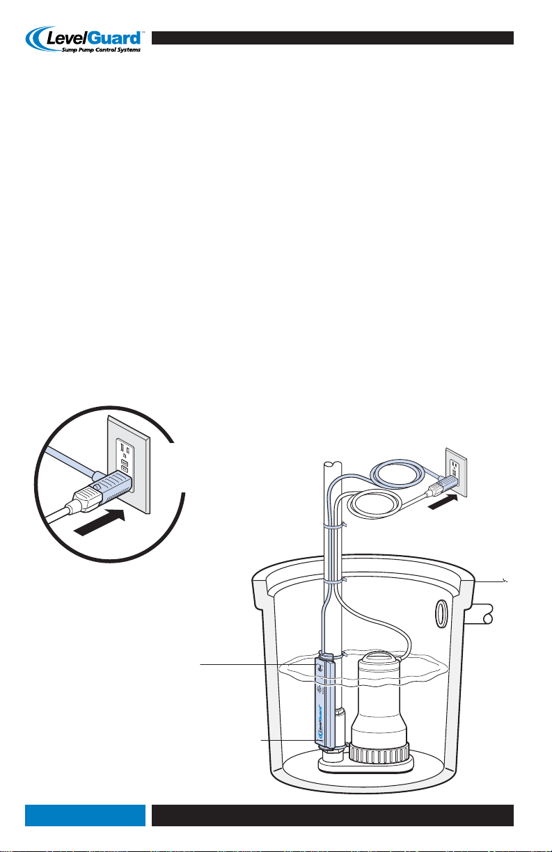
• Plug the LevelGuard Sump Pump Control ONLY into a properly grounded, Ground Fault Circuit
Interrupt (GFCI) receptacle.
NOTICE: These instructions assume that local code enforcement requires the use of a GFCI receptacle.
(Codes may vary by geographical jurisdiction.)
• GFCI receptacle must be installed by qualified electrician in accordance with all applicable codes
and ordinances.
• Before LevelGuard Sump Pump Control installation, a qualified person must test the GFCI to assure
that it is operating properly.
• Never remove the grounding prong; never modify the plug or GFCI in any way; do not use any
adapter plugs.
• Keep cord away from sharp edges, heat, oil, or moving parts. Discontinue use immediately if cord
is damaged.

www.LevelGuardProducts.com | 5
Application
NOTICE: Sincethe LevelGuard™Sump PumpControl worksincombination withanother Manufacturer’s
pump, you must read and follow the Manufacturer’s instructions for that pump. Failure to do so may
void the warranty or cause product damage.
• The LevelGuard Sump Pump Control is designed to work as a water-detecting switch for sump pumps
made by other manufacturers.
• Any connected sump pump must operate within the “Performance Specifications” listed below.
Improper use, modification, or installation of this device may cause damage to the product and
surrounding equipment.
• Includes thermal protection designed to prevent burnouts due to electrical overload.
• Includes fused over-current protection to safe-guard users from pump failure modes resulting in
high electrical current.
• LevelGuard Home Sump Pump Controls are designed for residential use only.
• NOTDESIGNED towork incaustic chemical fluidsor solutions.DO NOTuse fordetecting oil, alcohol,
or petrochemical solutions. Not warranted to function in mixtures containing heavy foreign materials.
• It is strongly recommended that an alternative system be used to protect against power outages,
excessive water flow, GFCI tripping, and primary pump failure.
Performance Specications
• For use ONLY with 120-VAC, 60Hz, single-phase current only. Do not use with 240VAC systems.
• Current draw while in operation: 1.3 milliamps.
• Circuit Requirement: 15 amp dedicated branch circuit.
• Load Current Rating: 120VAC/12 amps continuous; ½ hp/D150 (72VA).
• Sensor Technology: Solid-State “Field-Effect”.
Environmental
• Ambient Operating Temperature: 0°C to 50°C; Storage Temperature: -40°C to 85°C.
• Ambient Liquid Operating Temperature: 0°C to 50°C.
Construction
• Housing Material: Plastic.
• Cord: SJT0W/14 Gauge. Includes piggyback female plug to receive cord from (and switch power to)
sump pump.
• Standard Cable Length: 8 ft (Model Z24802PTZ).
• Water Level turn on/ turn off range: approx. 6.7" (170mm) typical differential, non-adjustable.
Certications
• UL E332036, CUL E332036.
• RoHS Compliant.

6 | Sump Pump Control System
Installation Instructions
Unpack Materials
Contents of the package include:
• LevelGuard™Sump Pump Control with 8' cord
• Attachment Straps, quantity five (5)
(Sump pump not included)
Tools Required
In addition to the product, you may need:
• Cutters to trim ends of tie straps
• Screwdriver (slotted or Phillips, as required) to remove old tethered float switch from pump.
• Tape measure
(1) LevelGuard™ Sump Pump Control
(5) Attachment Straps
Tape Measure Screwdriver Cutters

www.LevelGuardProducts.com | 7
Disconnect and Discard
UNPLUG
Remove Existing Switch (optional; not required for new installations using pumps
which do not include switch function)
DANGER: Be positive that electrical power is disconnected from all circuits near the sump pump.
Contact a qualified electrician if necessary.
1. Shut off power to sump pump circuit.
2. Unplug sump pump and existing switch from outlet.
3. Remove sump pump from sump pit (optional).
4. Remove retaining screw(s) to disconnect existing tethered switch. Discard old switch.
(Actual procedure may differ from illustration and is dependent on your pump make and model.)
5. Reinstall sump pump into pit.

8 | Sump Pump Control System
Install LevelGuard™ Sump Pump Control
WARNING: DO NOT plug in LevelGuard™Sump Pump Control until instructed to do so.
1. Drain the sump pit (Recommended).
2. Loop provided tie straps through LevelGuard Sump Pump Control
holes at top and bottom as shown in Detail A. Leave about 3" of
slack for ease of installation.
3. Hold Sump Pump Control with cord up. Lower it into sump pit.
4. Place bottom of Sump Pump Control against discharge pipe,
at LOWEST level where you want water to be pumped. This is
where the Sump Pump Control turns the pump “OFF”.
NOTICE: If check valve is in the way, you can attach Sump Pump
Control onto the check valve (Detail B). Mount Sump Pump Control
facing AWAY from inlet pipe.
5. The Switch Point “ON” is 6.7" (170mm) above “OFF” level… so
water will rise about 6" before pump turns on.
6. BecertainthatoutwardfaceofSumpPumpControlhas2"(51mm)
MINIMUM CLEARANCE from any foreign objects.
7. Securely fasten top and bottom of Sump Pump Control to discharge pipe by tightening the two
tie straps (do not overtighten.)
Detail A
Minimum 2"
(5cm) Clearance
UNPLUG
6" Fluid Level
Control Range
“SWITCH OFF”Level
“SWITCH ON”Level
Mount Sump
Pump Control
AWAY from
Inlet Pipe
Check Valve
Inlet Pipe
Discharge Pipe
Discharge Pipe
Loop
(2) Tie Straps
Through
Leave 3" of slack for
installation ease
Detail B

www.LevelGuardProducts.com | 9
Electrical Connection
WARNING: Perform ALL cord management and routing BEFORE turning on main power and before you
plug into the GFCI outlet.
1. Find a path where sump pump and LevelGuard™Sump Pump Control cords will be protected from
all sharp objects, hot surfaces, oils, and chemicals.
2. Use provided tie straps to fasten cords to the discharge pipe.
GFCI
Protected
Outlet
UNPLUG
Discharge Pipe

10 | Sump Pump Control System
3. Plug pump cord into back of the LevelGuard™Sump Pump Control piggyback plug.
DANGER: TheGroundFaultCircuitInterrupt(GFCI)receptaclemustbeinstalledbyaqualifiedelectrician
in accordance with all applicable codes and ordinances.
Before you connect to the GFCI, a qualified electrician must test the GFCI to assure that it is operating properly.
4. Insert Sump Pump Control plug ONLY into a GFCI ground-fault protected outlet that is operating properly.
5. Recheck plugs for firm connection.
6. Turn Main Power to circuit “ON”.
Test
1. Allow water to fill the sump pit up to the Switch “ON” Point on the LevelGuard Sump Pump Control.
2. SumpPumpControl “TurnsON”the pump two(2)seconds afterwaterrisesto the“SwitchOn” Point.
Sump Pump Control “Turns OFF” when water is pumped to bottom of the Control “Switch Off” Point.
If pump does not operate:
• TURN OFF electrical circuit that supplies the GFCI receptacle.
• Re-check plugs for firm connection.
• Reset GFCI receptacle.
• Re-connect electrical circuit.
• Consult “Trouble-Shooting” chart if problems continue.
“SWITCH OFF” When Water
is Pumped Down to Bottom
“SWITCH ON”
When Water Reaches Top
GFCI
Protected
Outlet

www.LevelGuardProducts.com | 11
Trouble-Shooting for LevelGuard™ Sump Pump Control
1. Sump Pump Control cord improperly
plugged into receptacle.
2. Pump cord improperly plugged
into Sump Pump Control plug.
3. Blown panel fuse or breaker.
4. GFCI receptacle tripped.
5. Low Voltage.
6. Main Power Outage.
7. Defective Pump.
8. Contamination build-up on
Sump Pump Control exterior.
9. Improper Mounting / Loose.
10. Damaged or defective Sump
Pump Control.
1. Significant in-flow of water.
2. Sump Pump Control mounted
facing inlet pipe.
3. Defective check-valve.
4. Defective Pump.
5. Excessive Temperature.
6. Improper Mounting / Loose.
7. Damaged or defective Sump
Pump Control.
1. Contamination build-up on Sump
Pump Control exterior.
2. Improper Mounting / Loose.
3. Foreign conductive object near
sensor pad.
4. Damaged or defective Sump
Pump Control.
1. Properly insert plug
into receptacle.
2. Properly insert pump cord into Sump
Pump Control piggyback plug.
3. Replace with proper sized fuse
or reset breaker.
4. Reset GFCI receptacle.
5. If voltage under 108 volts, contact
qualified electrician.
6. System will not work without power.
7. See Pump Manufacturer’s
Operators Manual.
8. See Maintenance Guide for proper
cleaning instructions.
9. See Sump Pump Control Installation
Instructions.
10. Contact LevelGuard Customer Service.
1. Normal. Check Pump Specification to
confirm adequate pumping capacity.
2. Move Sump Pump Control away from
inlet pipe.
3. Replace check-valve.
4. See Pump Manufacturer’s Operator
Manual.
5. Let system cool down for 5 minutes.
6. See Sump Pump Control Installation
Instructions.
7. Contact LevelGuard Customer Service.
1. See “Maintenance Guide” for proper
cleaning instructions.
2. See Sump Pump Control Installation
Instructions.
3. Remove foreign object.
4. Contact LevelGuard Customer Service.
Pump will not
start or run
Pump starts
and stops
too often
Pump will not
shut off when
water is not
present at the
lower limit
Symptom Possible Root Cause(s) Potential Corrective Action

12 | Sump Pump Control System
5-Year Limited Warranty
The LevelGuard™Sump Pump Control is warranted for five (5) years from date of purchase, for manufacturer’s defects ONLY.
Up to five (5) years from date of purchase, TouchSensor Technologies will replace, at its option, for the original purchaser any part or parts
of its LevelGuard™Sump Pump Control (“Product”) found upon examination by TouchSensor Technologies to be defective in materials or
workmanship.Bepreparedto providethe completeproduct andproof ofpurchase receiptand completedwarranty claimform whenexercising
this warranty. All transportation charges on Products or parts submitted for evaluation or replacement must be paid by purchaser.
ThisLimited Warrantydoes NOTcover productswhichhavebeendamaged asa resultof accident,abuse,misuse, neglect,improper installation,
improper maintenance, pump failure resulting in an over-current electrical condition, or failure to operate in accordance with LevelGuard™
written instructions.
THEREISNO OTHEREXPRESSWARRANTY,IMPLIED WARRANTIES,INCLUDINGTHOSE OFMERCHANTABILITYAND FITNESSFORAPARTICULAR
PURPOSE, OR LIFETIME WARRANTY FROM THE DATE OF PURCHASE. THIS IS THE EXCLUSIVE REMEDY AND ANY LIABILITY FOR ANY AND ALL
INDIRECT OR CONSEQUENTIAL DAMAGES OR EXPENSE WHATSOEVER IS EXCLUDED.
In no event, whether as a result of breach of contract warranty, tort (including negligence) or otherwise, shall TouchSensor Technologies or
its suppliers be liable for any special, consequential, incidental or penal damages including, but not limited to loss of profit or revenues, loss
of use of the products or any associated equipment, damage to associated equipment, cost of capital, cost of substitute products, facilities,
services or replacement power, downtime costs, or claims of buyer’s customers for such damages.
In the event that you need to exercise a warranty claim, please visit our website at www.LevelGuardProducts.com to attain electronic copies of
the warranty claim forms and instructions relating to the claim submission process.
How to Contact TouchSensor Technologies for warranty related information
Call our customer care center at 1-877-342-3261 (From Canada, call 1-630-221-9000)
Or write us at: Customer Care Center Proof of Purchase & Product Information
TouchSensor Technologies Store Name _____________________________________
c/o LevelGuard™Products Date Purchased _____________________________________
203 North Gables Blvd. Model Number _____________________________________
Wheaton, IL 60187 Serial Number _____________________________________
levelguard@touchsensor.com
Maintenance Guide
WARNING: Unplug LevelGuard™Sump Pump Control and Pump from all electrical power BEFORE
doing any service or maintenance.
• Inspect area around Sump Pump Control and clear all foreign objects and buildup.
• Plug Sump Pump Control and Pump back into GFCI wall outlet after inspection. Check for proper operation.
• We recommend that you do this maintenance at least once a year. However, harsh environmental
conditions will dictate the necessity of your actual maintenance schedule.
GFCI Receptacle
NOTICE: Therecommendeduse ofa GFCI receptacleis meantforyour protection. Aspartof itsdesigned
function, a GFCI receptacle can “trip” (turn off power supply) in cases of ground faults.
Because the GFCI receptacle can trip and cut off power to the pump, we recommend that you FOLLOW
THE RECEPTACLE MANUFACTURER’S INSTRUCTIONS for test and reset procedures.
Service & Repair
• The LevelGuard Sump Pump Control contains NO serviceable parts.
• Do not disassemble Sump Pump Control. Doing so can result in death or electrical shock and
voided warranty.
• If Sump Pump Control stops working, refer to troubleshooting instructions provided in this manual.
• If part is under warranty, follow warranty instructions provided in this manual or visit us at
www.LevelGuardProducts.com.
• If part is not under warranty, disposal of unit is necessary following local and or regional codes.
Inx-Levelguard-Sump, Rev. A, 2010/06
©2010 TouchSensor Technologies, LLC
LevelGuard™is a trademark of TouchSensor Technologies, LLC • 203 North Gables Blvd. • Wheaton, IL 60187
Protected under the following U.S. Patent Numbers: 5594222, 6310611, 6320282, 7373817.
This manual suits for next models
1
Table of contents
Popular Switch manuals by other brands

Darter
Darter EDS-301 user manual

Intermatic
Intermatic R8816P101C supplementary guide

GE Security
GE Security EtherNAV D7600 Series Installation & operation manual

Hammond
Hammond Leslie CU-1 owner's manual

CAMDEN
CAMDEN CM-336 installation instructions

Baumer
Baumer DS93 Installation and operating instructions