The door must be made of connuous corrugated sheet construcon and spring
balanced
Door Axle diameter must not exceed 35mm
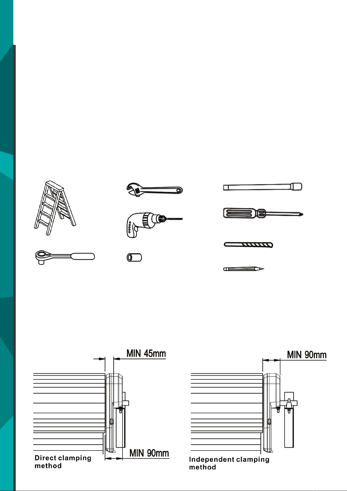
Ensure that there is at least 45mm from the edge of the curtain to the edge of
the bracket.
Ensure there is a power point near the opener. Portable Power Generators are
not recommended.
If the roller door drum is on the edge of the curtain or is a smaller diameter,
addional clearance may be required.
If the drum is more than 60mm from the curtain edge or of a smaller diameter,
an extension pole kit may be required (secon 5.7)
5. DOOR PREPARATION
Complete the following test to ensure
that your door is well balanced, and not
scking or binding.
• Disable all locks and remove any
ropes connected to the garage door.
• Li the door to about halfway and
then release it. The door should
remain spring balanced.
• Raise and lower the door to
determine if there are any scking
or binding points (20kgf is the
absolute maximum allowable to
raise or lower the door in any
posion).
• Clean the Guides of any oil or wax built up
• Install locking bar covers if there are locking bar holes in the guides. This
ensures fingers cannot be placed in the holes while the door operates
• Place included warning label so they are visible on the inside of the door
If your door does not hold in place or the door binds or sticks, have your roller door
attended to by a qualified technician before installing the Roller door opener.
5.1 Testing the door
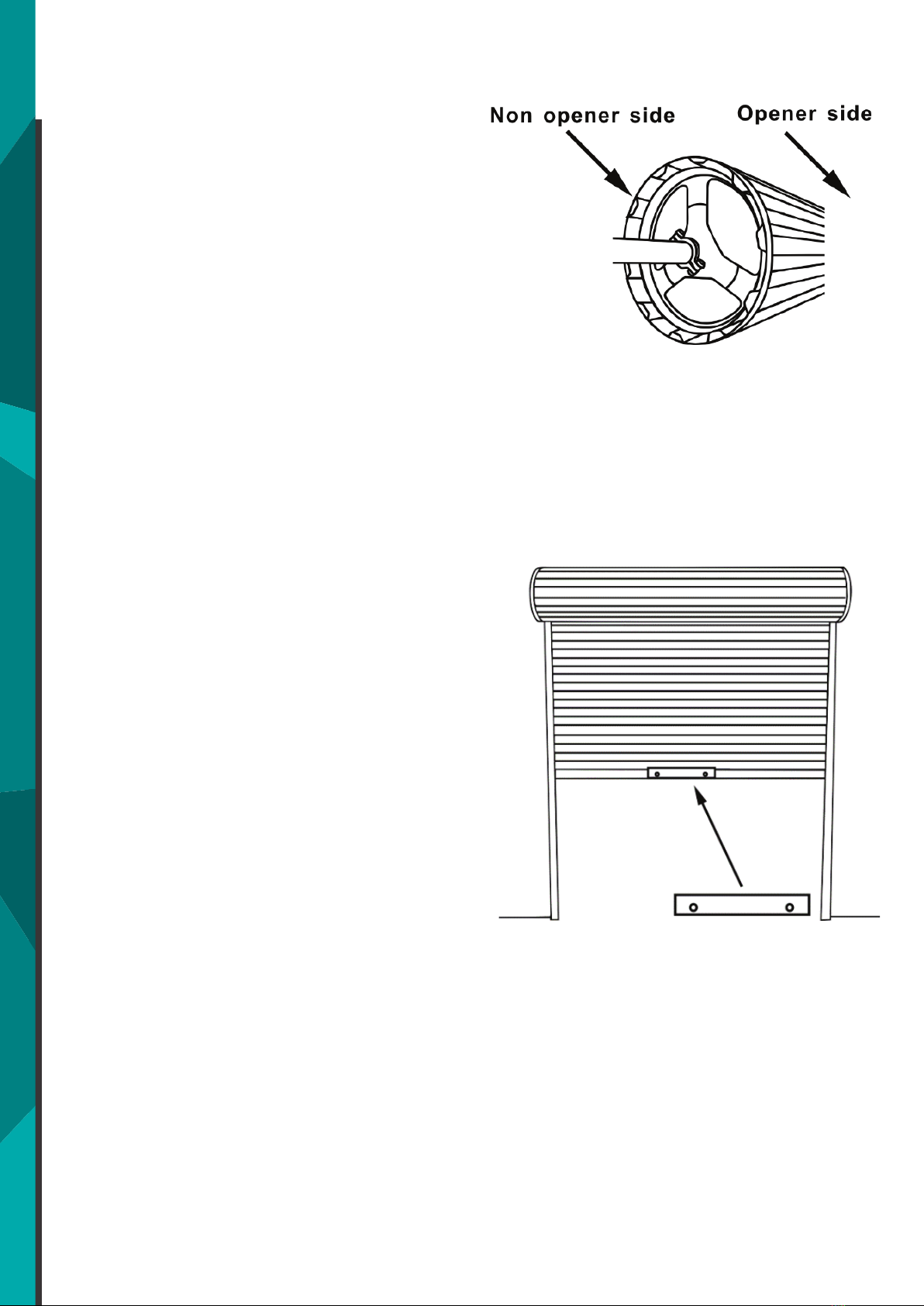
• Install the stop collar on the
opposite end to where the opener is
going to be installed.
ie – Right hand installation – Stop Collar
will be on the Left Hand side.
• Fit the stop collar hard against the
boss of the door drum.
• Ensure the U-Bolt holding the door
sha to the door bracket is ghtly
secured.
5.3 Installing the Weight Bar
If your roller door has a handle, a weight
bar is required to be installed prior to
installing the motor.
Garage door has existing handle:
• Remove the Handle, Nuts and Bolts.
• Place the weight bar over the handle
holes in the centre of the door on
the inside.
• Insert Extended Bolts through the
weight bar
• Fasten handle back in place
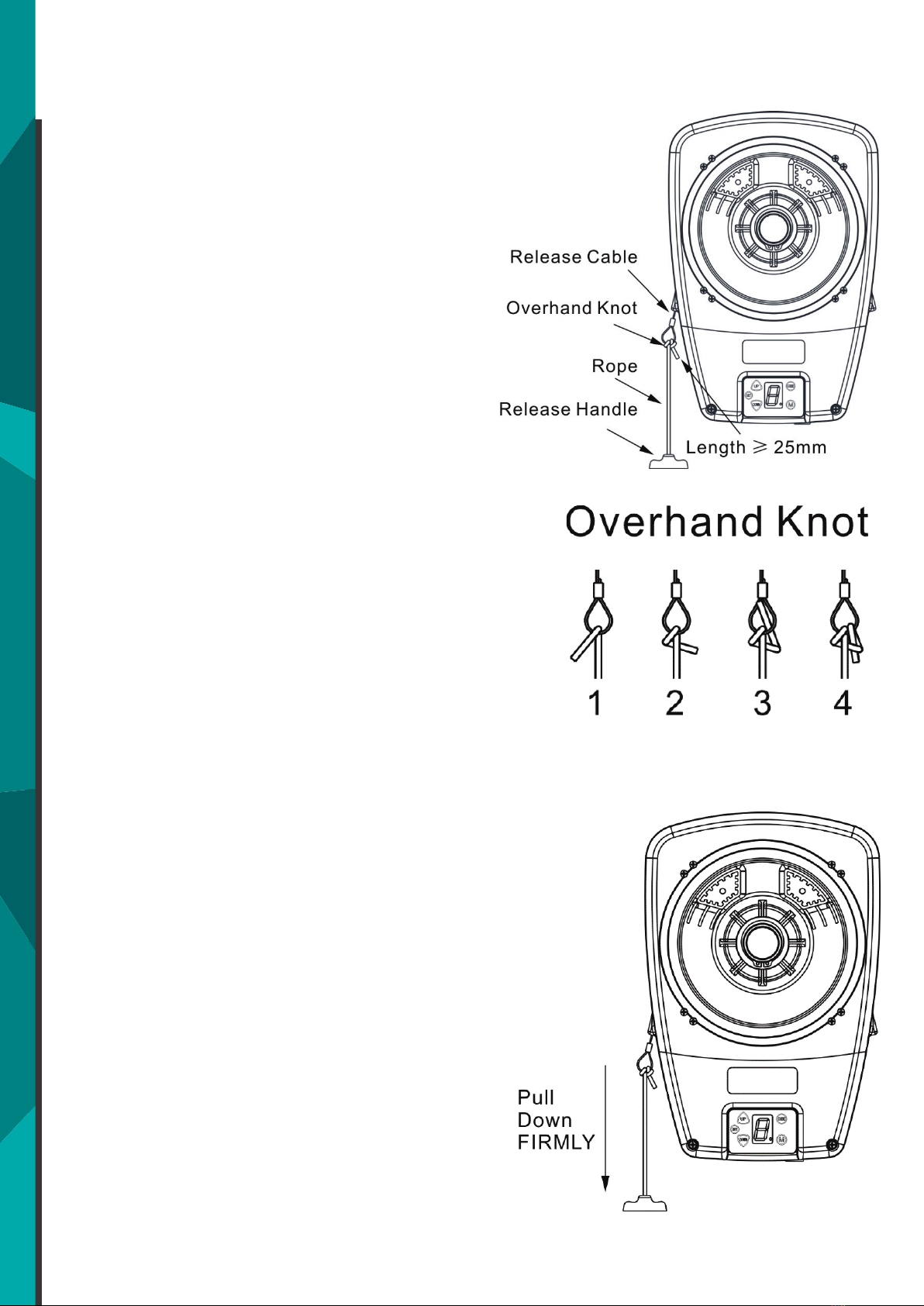
• Thread one end of the rope through
the hole in the top of the red
release handle so that “NOTICE”
reads right side up
• Secure with an overhand knot at
least 25mm from the end of the
rope to prevent slipping.
• Thread the other end of the rope
through the loop of the manual
release cable.
• Adjust rope length so the handle
(when installed) will be no higher
than 1.8m above the floor.
• Secure with an overhand knot.
Final adjustment of handle height
should be completed aer the opener is
installed. If it is necessary to cut the
rope, heat seal the cut end to prevent
unravelling.
Disengaging the Opener
• Pull the release cord down firmly
Re-engage the opener
• Pull the release cord down firmly
Disable all locks and remove any ropes
connected to the garage door. Take
care when operang the manual release
as an open door may fall rapidly due to
weak or broken springs or being out of
balance.
5.6 Pinning the Door
Pinning the rolling garage doors
curtain to the drum maintains
security when the opener is
closed and can affect the safety
reversal response. If the
curtain is not pinned the door
can be parally opened
manually.
• Close roller door fully
• Place self tapping metal
screws or rivets where the
curtain leaves the roll.
• Secure these through the
This accessory in not included in
standard package.
• Align the extension pole holes with
the drive legs.
• Slide the reinforcing brace over the
poles.
• Insert the extension poles into the
drive leg and fix in place using
screws provided.
Reinforcing brace MUST be used.
© LEXO Automaon Pty Ltd 2019 | www.lexo.com.au | Model RD1P1000A | Page 5/22