Physics Chemistry ⋅Biology Technics LEYBOLD DIDACTIC GMBH
11/97-kem-
Instruction sheet 451 281
451 292
The stroboscope with microprocessor-controlled xenon flash
tube can be used
•to observe rapid periodic motions, e.g. oscillations of a string,
as a stationary image
•to measure the frequency of periodic mechanical phenomena
(1 ... 330 Hz) and for speed measurements (60 ... 19,800 rpm)
•to observe a rapid motion process at different points in time,
e.g. during projection.
The stroboscope is designed to permit shifting of the flash pha-
se. This allows you to vary the observation point during a peri-
odic motion. The frequency and phase angle can be read off in
a display.
1 Safety notes
2 Description, scope of supply, technical data
1
-
7
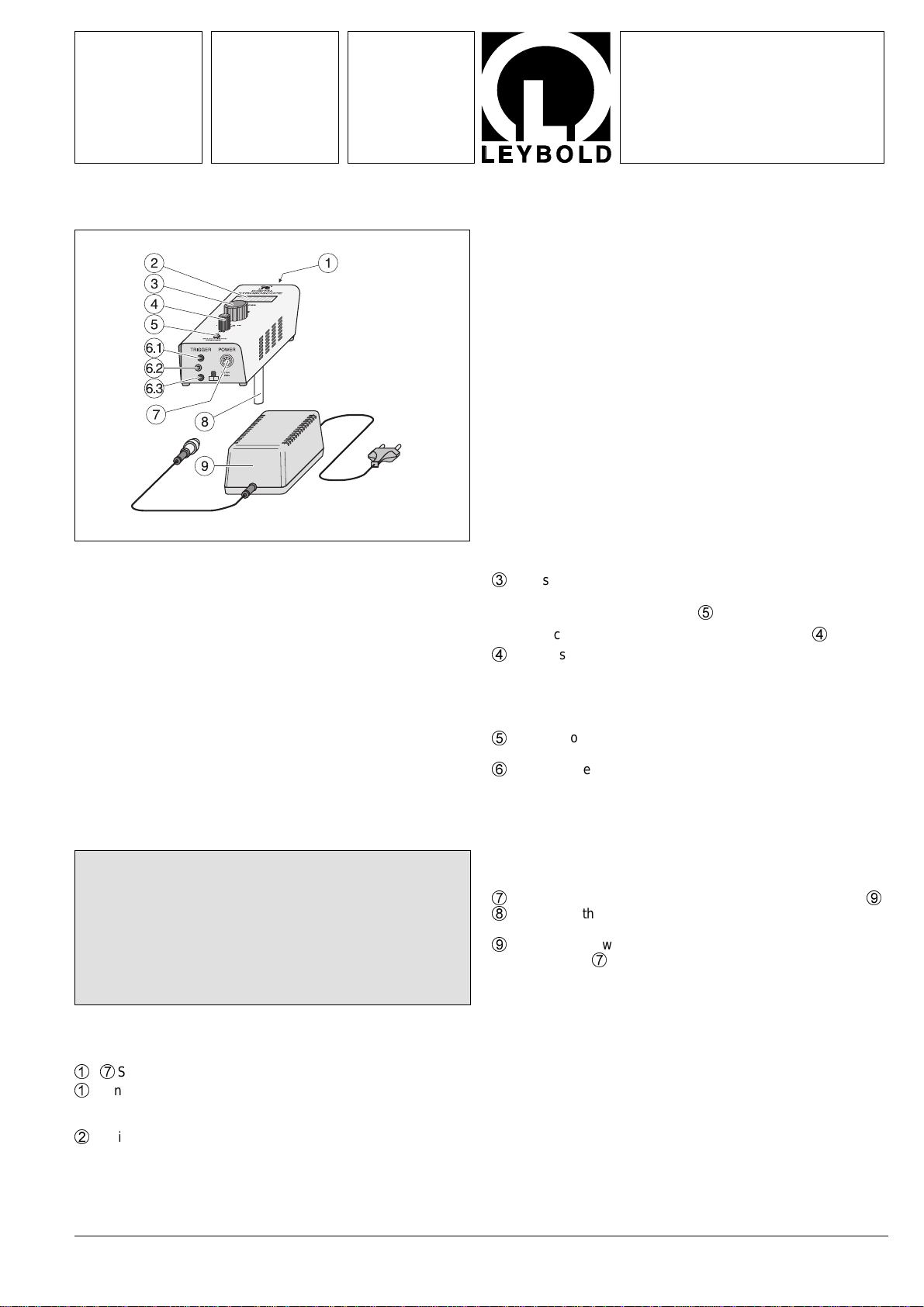
Stroboscope
1
Xenon flash tube, XSU 40, mounted in reflector;
behind removable plastic window,
Replacement: spare flash tube (451 292)
2
Digital display, 5-digit, for frequency and phase angle
3
Adjusting knob for continuous adjustment of frequency and
phase angle, ranges selectable
- Select the quantity with key
5
- Select the measuringrange with rotary switch
4
4
Rotary switch FPS (flashes per second):
1 - 1001...100 Hz
30 - 33030...330 Hz
OFF: switch off device
5
Pushbutton for toggling display between frequency and
phase angle
6
4-mm sockets for external control
(6.1) Output: 12 V DC (with respect to ground (6.3))
for connection to (6.2) via external switch (e.g. light
barrier 337 46)
(6.2) Signal input for external triggering of light flashes
connection voltage with respect to ground (6.3):
3...20 V
(6.3) Ground (0 V)
7
Connection socket for supply voltage from power supply
9
8
Stand rod, threaded
length: 125 mm, diameter: 10 mm, thread M6
9
Power supply with mains cable and connecting lead with
DIN plug for
7
Mains voltage: 85...250 V , 50/60 Hz, 30 W
Output voltage: 24 V DC, 1 A
Not shown: carrier bag
Dimensions:
Stroboscope: 81mm x 56 mm x 194mm
Power supply: 14 mm x 7 mm x 8 mm
Total weight: 0.6 kg
Stroboscope, 1...330 Hz
Spare Flash Tube
Fig. 1
•During operation, interference may occur in transmitting
and receiving devices or components. In this case, discon-
tinue using the stroboscope immediately.
Never leave the stroboscope on longer than is required to
carry out the measurement, and keep this period as short
as possible.
•Do not touch the spare flash tube with your bare fingers.


