PPM Sentinel 3 User manual

Sentinel 3
System & Accessory
Handbook
Version 1.11
S3x-HB-1-11
CR3991 18/01/19
Document
Revision
Summary of Changes
1.9
Additional features introduced in software release 1.05.000.
Corrections to REPORT remote command arguments.
1.10
Additional guidance on remote command responses.
New application and image update procedures for software release 1.05.001.
1.11
Corrections to GETTXSETTINGS remote command description
Corrected email and web addresses
Pulse Power & Measurement Ltd, 65 Shrivenham Hundred Business Park, Watchfield, Swindon, Wiltshire SN6 8TY, UK

S3x-HB-1-11
2
Instrument care and safety information
Please read the whole of this section before using your Sentinel 3 product. It contains important safety
information and will enable you to get the most from your fibre optic link.
Electrical Safety
The Sentinel 3 enclosure provides the termination for power inputs and can be fitted
with power supplies.
The Sentinel 3 enclosure is a “safety class 1”product (having metal chassis directly
connected to earth via the power supply cable).
When operating the equipment note the following precautions:
Hazardous voltages exist within the equipment.
PSU modules are fused on the mains live feed only. A second fuse should be used
for the neutral connection where the polarity of the connectors can be reversed.
the socket-outlet shall be installed near the equipment and shall be easily
accessible.
ESD Precautions
Precautions for handling electro-static sensitive devices should be observed when
handling all Sentinel 3 modules. Technicians should ensure that they use effective
personal grounding (i.e. ESD wrist strap etc.) when servicing the equipment. Any
equipment or tools used should be grounded to prevent static charge build-up. Good
practice should be observed at all times. For reference see relevant standards.
EN 61340-5-1, “Protection of Electronic Devices from Electrostatic Phenomena –
General Requirements”
Optical Safety
The Sentinel 3 enclosure may be fitted with optical units
The Sentinel 3 remote head and receiver modules contain laser diode sources
operating at nominal wavelengths of 1270nm to 1610nm.
These devices are rated as EN60825-1:2007 CLASS 1 radiation emitting devices. A
class 1 laser is safe under all conditions of normal use.
When operating the equipment note the following precautions:
Never look into the end of an optical fibre directly or by reflection either with the
naked eye or through an optical instrument.
Never leave equipment with radiating bare fibres –always cap the connectors.
Do not remove equipment external covers when operating.
Hot surface
When operated under full load and elevated temperature the Sentinel3 enclosure and
remote heads can become hot.
Suitable precaution should be taken when handling this device:
Allow to cool for 10 minutes
Do not touch metallic surfaces or printed circuit board when hot.
Heavy items
Some parts of this product can weigh in excess of 16kg.

S3x-HB-1-11
3
For heavy or awkward items, ensure that the correct precautions and safety
equipment are implemented to avoid injury and/or damage to equipment. If in doubt,
consult your Health & Safety representative.

S3x-HB-1-11
4
Table of contents
1INTRODUCTION TO FIBRE OPTIC LINKS...................................................................................10
1.1 Initial inspection....................................................................................................................10
1.2 Storage.................................................................................................................................10
1.2.1 Batteries.....................................................................................................................10
1.3 Important handling instructions............................................................................................10
1.4 Care of fibre optic interfaces................................................................................................11
2QUICK INSTALLATION GUIDE.....................................................................................................13
2.1 Module installation ...............................................................................................................13
2.2 Applying power.....................................................................................................................13
2.3 Optical cable installation ......................................................................................................13
2.4 Battery connection ...............................................................................................................13
3SENTINEL 3 SYSTEM DESCRIPTION .........................................................................................14
3.1 Basic system function ..........................................................................................................14
3.1.1 Receiver variants.......................................................................................................14
3.1.2 Setting gain................................................................................................................15
3.1.2.1 Standard gain range ...................................................................................15
3.1.2.2 Low noise gain range..................................................................................15
3.1.2.3 Sensitivity versus compression modes.......................................................16
3.1.2.4 Thermal compensation ...............................................................................16
3.1.2.5 Received Light Level (RLL) Automatic Gain Control (AGC).......................16
3.1.2.6 Factory calibration ......................................................................................17
3.1.3 High impedance mode...............................................................................................17
3.1.4 Passive integrator mode............................................................................................17
3.1.5 Transmitter Power Modes..........................................................................................17
3.2 Chassis.................................................................................................................................17
3.2.1 Housing......................................................................................................................18
3.2.1.1 Nineteen inch rack chassis.........................................................................18
3.2.1.2 Desktop chassis..........................................................................................18
3.2.2 Charger......................................................................................................................19
3.2.3 Controller ...................................................................................................................19
3.2.4 External control interfaces .........................................................................................20
3.3 Local receiver modules........................................................................................................21
3.3.1 Rx1 receiver module..................................................................................................21
3.3.2 Rx2 receiver module..................................................................................................21
3.3.3 Rx6 receiver module..................................................................................................22
3.4 Remote transmit heads........................................................................................................23
3.4.1 Tx1.............................................................................................................................23

S3x-HB-1-11
5
3.4.1.1 Tx1 battery pack: ........................................................................................24
3.4.2 Tx8.............................................................................................................................24
3.4.2.1 Tx8 battery pack: ........................................................................................24
3.5 Accessories..........................................................................................................................26
3.5.1 Cable assemblies.......................................................................................................26
3.5.1.1 Reels...........................................................................................................26
3.5.1.2 Cross-site cables ........................................................................................26
3.5.1.3 Patch cables ...............................................................................................27
3.5.2 Break-out boxes.........................................................................................................29
3.5.3 Cleaning kit ................................................................................................................29
3.5.4 Charge shoes.............................................................................................................30
3.5.4.1 Chassis charging ........................................................................................31
3.5.4.2 Desk-top charging.......................................................................................31
3.5.4.3 Battery charge display only.........................................................................31
3.5.5 Inverter shelf..............................................................................................................32
3.5.6 Charge shelf...............................................................................................................32
4GRAPHICAL USER INTERFACE..................................................................................................33
4.1 Overview Screen..................................................................................................................33
4.2 Rx Module Screen................................................................................................................34
4.3 Tx Head Screen ...................................................................................................................34
4.4 Warning and Error Messages ..............................................................................................36
4.4.1 Alarms........................................................................................................................36
4.4.2 Warnings....................................................................................................................37
4.5 Charger Screen....................................................................................................................37
4.6 Settings Screen....................................................................................................................37
4.6.1 Set Static IP Address.................................................................................................38
4.7 Updates................................................................................................................................39
4.7.1 Update Operating System Image ..............................................................................39
4.7.2 Update Application.....................................................................................................40
4.8 Shutdown Screen.................................................................................................................41
4.9 Remote Control Application .................................................................................................41
4.9.1 System Requirements ...............................................................................................44
4.9.2 Installation..................................................................................................................44
5EXTERNAL CONTROL INTERFACE COMMAND REFERENCE.................................................45
5.1 Ethernet connection .............................................................................................................45
5.2 Format..................................................................................................................................46
5.3 Remote Commands and Responses...................................................................................47
5.3.1 Response Times........................................................................................................47
5.4 Command set.......................................................................................................................48

S3x-HB-1-11
6
5.4.1 Measurement set-up commands...............................................................................48
5.4.2 Operational commands..............................................................................................50
5.4.3 Reporting commands.................................................................................................50
5.4.4 Common response strings.........................................................................................51
5.5 Legacy command comparison.............................................................................................53
6SOFTWARE RELEASE NOTES (2018-ON)..................................................................................56
7MAINTENANCE .............................................................................................................................57
7.1 Cables & connectors............................................................................................................57
7.2 Service .................................................................................................................................57
8LITHIUM BATTERY TRANSPORTATION.....................................................................................58
8.1 Tx1 battery...........................................................................................................................58
8.2 Tx8 battery...........................................................................................................................59

S3x-HB-1-11
7
Table of figures
Figure 1: Remote head and receiver module in transport case..................................................................10
Figure 2: Dirty fibre interface causes performance degradation.................................................................11
Figure 3: Cleaning fluid residue cross-contaminates clean fibres ..............................................................11
Figure 4: Clean interface (i) mated with contaminated interface (ii) results in permanent damage (iii)......12
Figure 5: Power Button ...............................................................................................................................13
Figure 6: Tx1 remote head with battery disconnected................................................................................13
Figure 7: Sentinel 3 desktop chassis with two Rx1, two Rx2, and one Rx6 fitted ......................................14
Figure 8 Transmitter and receiver settings for Rx (left) and Rx+ (right) series...........................................15
Figure 9: Sensitivity or compression mode setting .....................................................................................16
Figure 10: Nineteen inch chassis dimensions ............................................................................................18
Figure 11: Desktop chassis dimensions .....................................................................................................19
Figure 12: Rear view of the interface panel................................................................................................19
Figure 13: Rx6 receiver module dimensions...............................................................................................21
Figure 14: Rx6 receiver module with deployed removal handle.................................................................21
Figure 15: Single input Tx1 remote transmit head......................................................................................23
Figure 16: Tx1 single input remote transmit head dimensions ...................................................................23
Figure 17: Tx8 eight input remote transmit head dimensions
....................................................................................................................................................................24
Figure 18: Different cable reels available (dependant on cable type and length) ......................................26
Figure 19: Rx1 module cross-site cable and connector..............................................................................26
Figure 20: Rx2 module cross-site cable and connector..............................................................................27
Figure 21: Rx6 module cross-site cable and connector..............................................................................27
Figure 22: Rx1 module patch cable and connector ....................................................................................28
Figure 23: Rx2 module patch cable and connector ....................................................................................28
Figure 24: Rx6 module patch cable and connector ....................................................................................28
Figure 25: Rx2 & Rx6 break-out solutions..................................................................................................29
Figure 26: Rx1, Rx2, and Rx6 system configurations and break-out boxes...............................................29
Figure 27: Residue free cleaning fluid ........................................................................................................30
Figure 28: Cleaning sticks for Rx1, Rx2, & Rx6 optical connectors and cables.........................................30
Figure 29: Dry fibre cleaning tools ..............................................................................................................30
Figure 30: Sentinel 3 charging shoe ...........................................................................................................31
Figure 31: Desktop charger (left) and charge shoe status LED states (right) ............................................31
Figure 32: Top-level GUI display menu ......................................................................................................33
Figure 33: Rx Module icons (left: Rx1, right: Rx2)......................................................................................33
Figure 34: Tx head Icons (left: Tx1, right: Tx8)...........................................................................................33
Figure 35: Information area in Remote Mode.............................................................................................34
Figure 36: Rx Module screen (Rx6 connected) ..........................................................................................34
Figure 37: Tx Head Screen (Tx8 connected)..............................................................................................35

S3x-HB-1-11
8
Figure 38: Tx head screen popups (left: Tx head power control, middle: Input gain control, right: Part
Number etc. view).......................................................................................................................................35
Figure 39: Acknowledging the overdrive alarm...........................................................................................36
Figure 40: Receiver and transmitter warning message examples..............................................................36
Figure 41: Charger Screen .........................................................................................................................37
Figure 42: Settings Screen .........................................................................................................................38
Figure 43: Settings Screen Access Mode override.....................................................................................38
Figure 44: Switching between dynamic and static IP address assignment................................................39
Figure 45 Update image button ..................................................................................................................40
Figure 46 Update application button..........................................................................................................40
Figure 47 Application and image update screens.......................................................................................40
Figure 48 Shutdown screen........................................................................................................................41
Figure 49 : Sentinel 3 Remote Agent with Manual Commands disabled (disconnected)...........................42
Figure 50: Sentinel 3 Remote Agent with Manual Commands enabled (connected to a Sentinel 3 system)
....................................................................................................................................................................42
Figure 51: Options Menu.............................................................................................................................43
Figure 52: File Menu ...................................................................................................................................43
Figure 53: Log File Copy Dialog .................................................................................................................43
Figure 54: Ethernet to GPIB external adapter ............................................................................................45
Figure 55: USB to GPIB external adapter...................................................................................................45
Figure 56 Suggested Ethernet connection for remote control ....................................................................46

S3x-HB-1-11
9
Table of tables
Table 1 Standard and low-noise gain ranges .............................................................................................14
Table 2: Cross-site cable basic specification..............................................................................................27
Table 3: Patch cable basic specification.....................................................................................................29
Table 4: Measurement set-up commands ..................................................................................................49
Table 5: Operational commands.................................................................................................................50
Table 6: Common response strings............................................................................................................52
Table 7: Legacy command comparison......................................................................................................55

S3x-HB-1-11
10
1 Introduction to fibre optic links
The PPM fibre optic link system for test & instrumentation brings together a wide range of products
designed particularly to meet the needs of researchers and engineers with requirements for monitoring,
measurement, antenna remoting and data transmission in the EMP, EMC and High Voltage industries.
This handbook covers the specification, installation and use of the Sentinel 3 fibre optic link system and
its accessories.
1.1 Initial inspection
Unpack and inspect the equipment as soon as possible upon receipt. If there is any sign of damage or
any parts are missing, do not install the equipment; seek advice from PPM or your local agent.
Figure 1: Remote head and receiver module in transport case
The equipment received should match the delivery note that was shipped with the equipment. Contact
PPM or your local agent in case of any discrepancies.
The plug-in modules must be installed in the Desktop Case before use.
1.2 Storage
As the Sentinel 3 system includes remotely deployable units it is recommended that a storage and
transport case be purchased to facilitate safe storage and use.
1.2.1 Batteries
For maximum lifespan it is recommended that the battery is stored at a nominal +20°C (±10°C) with a 40-
50% charge.
Whilst storage of the battery is permissible up to +50°C it is not recommended. Prolonged storage at high
temperatures will dramatically shorten battery life.
1.3 Important handling instructions
The Sentinel 3 system is an intricate piece of test equipment so can be seriously damaged if knocked or
dropped. Remote heads contain sensitive electro-mechanical components that are susceptible to
excessive shock and vibration. Whilst every effort has been made to ensure the product is robust, care
should be taken when handling.

S3x-HB-1-11
11
1.4 Care of fibre optic interfaces
Fibre optic links are an excellent alternative to coaxial cable where galvanic isolation is required or long
distances are involved. Due to the nature of fibre however, additional care is required when handling,
installing, and using fibre optic products.
The single-mode fibre optic cable used with Sentinel 3 is terminated with an Angle-Polished Connector
(APC) so correct orientation when making the interface is essential. Particular care should be taken to
avoid confusion between APC (green) and PC (blue) connectors, as they look similar but will not yield the
same performance. It is important to position the alignment key on the cable connector with the matching
slot in the module.
Single-mode fibre is used for the Sentinel 3 system for its high performance characteristics. As this fibre
has a very narrow diameter (9μm) it is far more susceptible to dust contamination than the relatively large
area of a multi-mode fibre. To minimise disruption caused by dirt, the Sentinel 3 fibre optic connectors
incorporate automatic dust protection shutters to help minimise any dust ingress. Despite the use of these
shutters, the optical connectors should be cleaned in accordance with the instructions in this hand book
before each and every connection; even if they have been protected with dust caps.
The protective dust caps on the equipment and cable connectors should only be removed immediately
before the connection is made, and should be replaced immediately after disconnection. When the fibre
optic cables are not connected, it is essential that the cable and equipment connectors are protected by
the dust caps provided with the system. Failure to do so may result in damage to the fibre ends, which
are critical to the system performance.
It is extremely important to ensure mating fibre surfaces are clear of contamination. Small amounts of dirt
and dust on the surface of the fibre can cause significant insertion loss and return loss degradation.
Figure 2: Dirty fibre interface causes performance degradation
Using the correct cleaning product (fluids and swabs) is as important as cleaning the fibre interface itself.
If the wrong fluid is used a residue can be left behind which will then cross-contaminate any clean fibre
surfaces it comes into contact with.
Figure 3: Cleaning fluid residue cross-contaminates clean fibres
Connector performance will be compromised if its end face is scratched or chipped. Failure to clean the
fibre interface can result in permanent fibre damage and signal degradation.

S3x-HB-1-11
12
Figure 4: Clean interface (i) mated with contaminated interface (ii) results in permanent damage (iii)
All fibre optic cable is subject to a minimum bend radius, beyond which physical damage may occur to the
cable.

S3x-HB-1-11
13
2 Quick installation guide
This section provides a quick guide to setting up the Sentinel 3 system.
2.1 Module installation
The Sentinel 3 system is shipped without receiver modules fitted. To fit the receiver modules gently slide
the module along the card guides, ensuring that it does not foul any adjacent module, until the connector
at the rear of the module mates with the backplane PCB inside the chassis. Push the module firmly into
place then tighten the four front panel screws to ensure the receiver module stay in situ. Receiver
modules can be fitted to any slot, but unused slots should be fitted with the provided blanking panels to
ensure correct air flow.
2.2 Applying power
The Sentinel 3 system is mains powered and is rated to accept 85 - 264Vac, from 47 –63Hz, nominal
100-240Vac,from 50 to 60Hz. Connect the system to a mains power outlet with the provided cable. Ensure
the system isolation switch at the rear is set to the on position; the red LED on the front panel will light up.
Turn on the system controller by depressing the button on the front panel until the LED turns green. The
Sentinel 3 system will boot up to the top-level menu screen ready for use. Check the installed receiver
modules are recognised by the system.
Figure 5: Power Button
2.3 Optical cable installation
Ensure the fibre optic interfaces are cleaned (see previous section) with the appropriate cleaning kits.
Remove the dust cap from the cross-site fibre optic cable. To insert the cross-site optical cable into the
receiver module position the alignment key on the cable connector with the slot on the module bulkhead
and push until the locking collet clicks. To remove the connector slide the locking collet backwards then
remove the connector.
2.4 Battery connection
To prevent unwanted shield degradation the Sentinel 3 remote head has no external power switch. The
remote head is activated by connecting the battery, and de-activated by dis-connecting the battery.
Figure 6: Tx1 remote head with battery disconnected

S3x-HB-1-11
14
To connect the battery ensure the 8-pin connector on the battery is aligned with the 8-pin connector on
the head and slide the battery into place; clamp the battery into place with the latch(es).
3 Sentinel 3 system description
The Sentinel 3 system is designed to be highly configurable to suit different customer applications. In its
most basic form a single input remote transmit head (Tx1) is connected via a fibre optic cable to a single
input receiver module (Rx1) that is fitted into a chassis.
The system can be expanded into more complex formats using an eight input remote transmit head (Tx8),
a dual input receiver module (Rx2), and a six input receiver module (Rx6). Three different types of fibre
optic cable are required for each of the three receiver module variants.
Figure 7: Sentinel 3 desktop chassis with two Rx1, two Rx2, and one Rx6 fitted
3.1 Basic system function
The Sentinel 3 system provides a non-galvanic inter-connection between a local measurement system
and remote probes i.e. between a signal analyser and current probe. The system is designed to minimise
additional distortion during signal transport, however the flexible nature of the system requires the user to
configure the system appropriately for their measurement scenario.
3.1.1 Receiver variants
Initial receiver cards (Rx1, Rx2 and Rx6) employed modules providing a maximum gain of approximately
20dB, these have been superseded by 35dB variants designated Rx1+, Rx2+ and Rx6+.The table below
shows the settable the link gain ranges when using the Rx and Rx+ series.
Model
Standard gain range (dB)
Low noise gain range (dB)
Rx series
-78 - 0
+1 - +40
Rx+ series
-63 - +15
+16 - +55
Table 1 Standard and low-noise gain ranges

S3x-HB-1-11
15
The receiver type is indicated on the receiver GUI screen and the settable gain range is indicated on the
gain control of the transmitter GUI screen.
Figure 8 Transmitter and receiver settings for Rx (left) and Rx+ (right) series
3.1.2 Setting gain
The gain of the Sentinel 3 system is controlled from the touch screen display by setting a single value..
This user set gain value is interpreted by the system to allow the appropriate RF line-up adjustments to
be made; providing the required end-to-end gain value whilst maximising the overall link performance.
The system principally operates in two gain modes, standard and low-noise; switching between the two
modes occurs seamlessly when the user-set gain value crosses the 15dB threshold for the Rx+ series or
0dB for the Rx series. Achieving the low-noise performance requires the system to re-configure itself; this
has an effect on other link performance parameters such as input compression and Instantaneous
Dynamic Range (IDR).
If the transmitter overdrive alarm is triggered, the transmitter will enter protection mode. When the source
of the overdrive is removed, the transmitter overdrive alarm must be reset by acknowledgement from the
user interface or remote interface.
3.1.2.1 Standard gain range
The standard gain range of the system is from -63dB to +15dB for the Rx+ series (-78dB to 0dB for Rx
series modules).
When configured for maximum attenuation the system can handle a ±200Vpk 500ns FWHM input signal;
no more than +26dBm should be applied as a Continuous Wave (CW) signal. When this value of
attenuation is set the system is at its least sensitive and the IDR is restricted to ~45dB.
Setting the system gain to <15dB reduces the input pulse handling level whilst increasing the sensitivity;
this increases the overall IDR to ~60dB.
3.1.2.2 Low noise gain range
The low-noise gain range of the system is from +16dB to +55dB for the Rx+ series (+1dB to +40dB for Rx
series modules).
When configured for maximum sensitivity the system has +55dB of gain and a noise figure ~5dB. Setting
the gain to ~25dB achieves the optimum IDR of ~55dB in this mode. In this mode the input compression
is limited by the front end amplification so care must be taken not to overdrive the system.
S3x-HB-1-11
16
3.1.2.3 Sensitivity versus compression modes
As the end-to-end gain is adjusted by the user, various attenuators in the Sentinel 3 system are adjusted
to maintain the programmed gain.
When the system is set to favour sensitivity, these automatic adjustments are preferentially made in the
transmit head to maximise the system’s sensitivity, but this comes at the expense of system’s
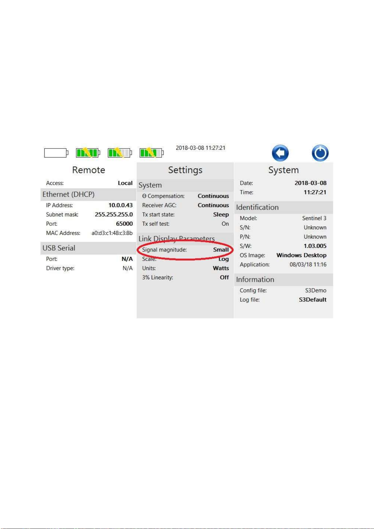
compression point. To configure this mode the signal magnitude setting should be set to “small”.
If the system is set to favour compression, these automatic adjustments are preferentially made in the
receiver module to maximise the system’s compression point, but this comes at the expense of the
system’s sensitivity. This adjustment can be made on the settings screen as shown below. To configure
this mode the signal magnitude setting should be set to “large”.
Figure 9: Sensitivity or compression mode setting
3.1.2.4 Thermal compensation
The Sentinel 3 system supports a thermal compensation feature that works to maintain the set gain value
over the operating temperature of the product. Once the overall link gain is set on the Graphical User
Interface (GUI) by the user, the system monitors any ambient temperature fluctuations and transparently
adjusts the internal attenuators to keep the actual gain within 0.25dB of the set value.
If a user is concerned about continuous gain adjustments occurring during their measurement cycle, this
feature can be de-activated using the GUI. In this case the last attenuator set value is retained with no
further adjustments being made until the user re-activates the feature.
An intermediate mode can be selected that restricts the thermal check and adjustment routine, only
allowing it to occur when the user manually changes the set gain value on the GUI or by remote
command. This mode achieves a reasonable degree of gain accuracy whilst preventing gain adjustments
being made mid-measurement.
3.1.2.5 Received Light Level (RLL) Automatic Gain Control (AGC)
The system can be configured in a number of different ways. Different fibre optic cable lengths can be
connected between the remote transmitter and local receiver modules and a number of breakout
solutions can be placed between them. To accurately realise and maintain the user set gain value for all

S3x-HB-1-11
17
of these different configurations, the system is required to monitor the optical interface and compensate
the gain value.
The optical monitoring occurs at the input to the local receiver module, with the measured Receive Light
Level (RLL) being displayed on the receive module menu in the GUI. A coarse indication of the RLL is
also displayed on the receive module icon at the GUI top level display. Any losses that occur in the optical
domain over and above the factory calibrated level are then compensated for using the receive module’s
AGC. If the RLL is below the level required for the AGC to stabilise a warning is displayed on the GUI; to
clear this warning the cable routing and cleanliness of the fibre connectors will need to be checked. If the
AGC is unable to stabilise for more than 30 seconds the system stops trying to stabilise and displays a
notification. Disconnecting the fibre cable and reconnecting it will re-start the receiver’s AGC stabilising
process.
If a user is concerned about continuous gain adjustments occurring during their measurement cycle, this
feature can be de-activated using the GUI. In this case no AGC is applied until the user re-activates the
feature.
An intermediate mode can be selected that restricts the application of AGC, only allowing it to occur when
the user manually changes the set gain value on the GUI or by remote command. This mode achieves a
reasonable degree of gain accuracy whilst preventing gain adjustments being made mid-measurement.
3.1.2.6 Factory calibration
Each remote transmitter and local receiver is calibrated to a factory standard, allowing any remote to be
used in combination with any receiver module; no permanent pairing of remote/receiver is required.
3.1.3 High impedance mode
If required, any of the remote transmitter inputs can be set to a high impedance mode. As the native
impedance of the system is 50Ω the high impedance performance is naturally constrained to ~500MHz.
For the Tx8 type of remoted head the high impedance mode can be set on a per input basis, allowing
each of the eight inputs to be set to a combination of high or 50Ω impedances depending on what probe
type is attached. Once the input configuration has been set up the user can freely switch between inputs
without needing to further update the input impedance.
3.1.4 Passive integrator mode
The Sentinel 3 remote heads support three user selectable passive integrator time constants as standard.
These can be remotely set to 0.1µs, 1µs, or 10µs using the systems GUI. When using the passive
integrator the user selectable gain is limited to 0dB or less.
3.1.5 Transmitter Power Modes
Sentinel 3 transmitters support two power modes, Sleep and On. In the former, only the transmitter’s
communication functions are enabled. In this mode, the battery life is increased significantly for periods
when the transmitters will be known to be idle. When switched on, the RF and optical functions are fully
enabled. The Sentinel 3 system controls the start-up state of each transmitter according to user
preference. Transmitters may always be started in sleep mode, always started in fully on mode or in the
power mode set explicitly by the user prior to shutting down the system or disconnecting the transmitter
battery.
When the optical connection to the transmitter is removed, either by disconnecting the optical cable or
shutting down the connected receiver, the transmitter automatically reverts to the power saving Sleep
mode. For long periods of inactivity, the battery should be physically disconnected.
3.2 Chassis
The Sentinel 3 chassis houses the integrated system controller, the battery charger, and up to six
receiver modules.
S3x-HB-1-11
18
3.2.1 Housing
Two different formats of housing can be supplied to meet varying customer requirements. The Sentinel 3
system can be configured as a desktop solution or as a nineteen inch rack mountable chassis.
Power to the chassis is supplied to the rear of the unit via an IEC C13 power cable. An isolating switch is
provided at the power ingress point along with a replaceable fuse. Input Power ratings are: 100- 240V AC
3.3Amps, Fuse rating: 5A. Power rating information can also be found on the rear of the chassis above
the input power connector.
At the rear of the chassis there are three fans to aid cooling. The chassis immediately behind the control
screen provides air flow over the main chassis power supply; this operates whenever the internal
temperature reaches a set level. The other two fans provide air flow for the receiver modules; these only
operate when receivers are plugged into the appropriate slots.
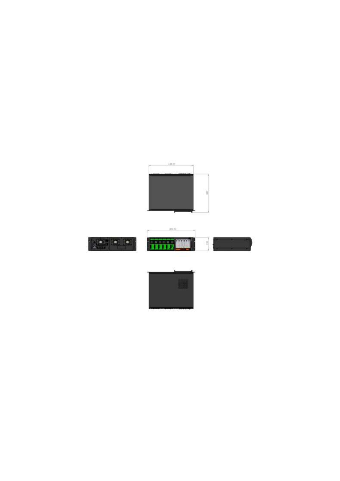
3.2.1.1 Nineteen inch rack chassis
The nineteen inch rack chassis is 3U high and can be mounted into a standard rack using the fixings on
the side of the chassis.
Figure 10: Nineteen inch chassis dimensions
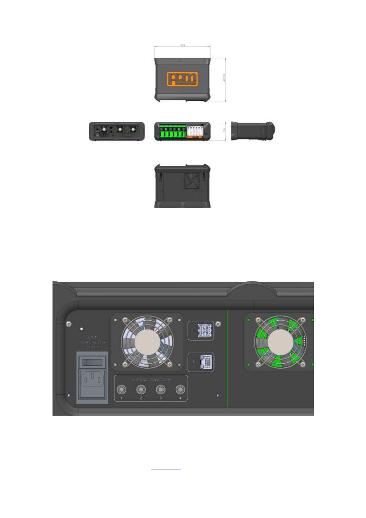
3.2.1.2 Desktop chassis
The desktop chassis has additional surround making it more robust. The rubber surrounds provide a
degree of shock protection and allow the system to be set down without damage to the product. Feet are
provided on the underside of the desktop chassis to raise the screen into a more comfortable position for
use and handles are included on the side panels to facilitate correct manual lift. The dust screen on the
underside of the unit is removable to aid cleaning.
S3x-HB-1-11
19
Figure 11: Desktop chassis dimensions
3.2.2 Charger
On the rear of the unit are the four HR10 charge ports. These can be used to connect either Tx1 or Tx8
batteries to the chassis using the appropriate charge shoe (section 3.4) and supplied cable. When
connected the battery’s charge status will appear on the front panel display. A battery can be charged by
any one of these ports, or up to four batteries can be charged simultaneously. These ports are protected
by an internal resettable fuse.
Figure 12: Rear view of the interface panel
3.2.3 Controller
The Sentinel 3 controller is an integral part of the chassis and cannot be removed. The controller provides
a touch screen interface to the Sentinel 3 system’s proprietary Graphical User Interface (GUI). A detailed
description of the GUI can be found in section 4.0. When the rear isolation switch is set to the on (1)

S3x-HB-1-11
20
position the front panel LED is lit red. Pressing and holding the power button on the front panel activates
the system controller; the front panel LED is lit green.
3.2.4 External control interfaces
Full remote emulation of local commands can be achieved by connecting to the Sentinel 3 system using
either the USB or LAN interfaces on the rear of the unit (section 4.7). GPIB control can be supported with
an external dongle.
The USB ports can be used to attach an external keyboard and mouse or USB mass storage device for
diagnostic log file transfer and updates to the system software (section 4.5).
Table of contents


