LG LW1100N User manual

LG GoldStream
Page 1of39
LG GoldStream
Wireless LAN PC Card
User’s Guide
LW1100N/LWL-1100P

LG GoldStream
Page 2of39
Contents
Chapter 1 Introduction To The Wireless LAN
1.1 What’s the Wireless LAN? …………………………………… 5
1.2 Wireless LAN Standard andStructure…………………………6
Chapter 2 Before You Start GoldStream………………………….12
Chapter 3 Installing GoldStream Card On The Windows OS
3.1 Installing PC CardAdapter. ….…………………………………13
3.1.1 Installing the PC Card Driver for Windows OS… …14
3.1.2 PC Card (PCMCIA) Network Configuration………18
3.1.3 Uninstalling PC Card Software …………………….23
3.1.4 RemovePCCardfromPC card socket……………23
3.1.5 GoldStream Configuration Utility ………………….24
3.2 PCI Card Installation……………………………………………..28
3.2.1 Installing PCI Card Adapter ………………………….29
3.2.2 Installing PCI Card Driver …………………………….31
3.2.3 PCI Card Network Configuration…………………….31
3.3 Troubleshooting…………………………………………………..32
Appendix
Appendix A CellPlanning(Radio Range)……………………………..34
Appendix B TechnicalSpecification………………………………….36
Appendix C Channel Allocation……………………………..…………38

LG GoldStream
Page 3of39
THE SPECIFICATIONS AND INFORMATION REGARDING THE PRODUCTS IN THIS MANUAL ARE SUBJECT TO CHANGE WITHOUT
NOTICE. ALL STATEMENTS, INFORMATION, AND RECOMMENDATIONS IN THIS MANUAL ARE BELIEVED TO BE ACCURATE BUT
ARE PRESENTED WITHOUT WARRANTY OF ANY KIND, EXPRESS OR IMPLIED. USERS MUST TAKE FULL RESPONSIBILITY FOR
THEIR APPLICATION OF ANY PRODUCTS.
THE SOFTWARE LICENSE AND LIMITED WARRANTY FOR THE ACCOMPANYING PRODUCT ARE SET FORTH IN THE
INFORMATION PACKET THAT SHIPPED WITH THE PRODUCT AND ARE INCORPORATED HEREIN BY THIS REFERENCE. IF YOU
ARE UNABLE TO LOCATE THE SOFTWARE LICENSE OR LIMITED WARRANTY, CONTACT YOUR LG REPRESENTATIVE FOR A
COPY.
The following information is for FCC compliance of Class B devices: The equipment described in this manual generates and may radiate
radio-frequency energy. If it is not installed in accordance with LG’s installation instructions, it may cause interference with radio and
televisionreception. This equipment has been tested and found to comply with the limits for a Class B digital device in accordance with the
specifications in part15 of the FCC rules. These specifications are designed to provide reasonable protection against such interference in a
residentialinstallation.However,there is no guarantee that interference will not occur in a particular installation.
Modifying the equipment without LG’s written authorization may result in the equipment no longer complying with FCC requirements for
Class A or Class B digital devices. In that event, your right to use the equipment may be limited by FCC regulations, and you may be
required to correct anyinterference to radio or television communications at your own expense.
You can determine whether your equipment is causing interference by turning it off. If the interferencestops, the LG equipment or one of its
peripheral devices probably caused it. If the equipment causes interference to radio or television reception, try to correct the interference by
using one or more of the following measures:
• Turnthe television or radio antenna until the interference stops.
•Movethe equipmenttoone side or theother of thetelevision or radio.
• Movethe equipmentfarther away fromthe televisionor radio.
• Plug the equipment into an outlet that is on a different circuit from the television or radio. (That is, make certain the equipment and the
television or radios are on circuits controlled by different circuit breakers or fuses.)
Modifications to this product not authorized by LG Systems Co., Ltd. could void the FCC approval and negate your authority to operate the
product.
NOTWITHSTANDING ANY OTHER WARRANTY HEREIN, ALL DOCUMENT FILES AND SOFTWARE OF THESE SUPPLIERS ARE
PROVIDED “AS IS” WITH ALL FAULTS. LG AND THE ABOVE-NAMED SUPPLIERS DISCLAIM ALL WARRANTIES, EXPRESSED OR
IMPLIED, INCLUDING, WITHOUT LIMITATION, THOSE OF MERCHANTABILITY, FITNESS FOR A PARTICULAR PURPOSE AND

LG GoldStream
Page 4of39
NONINFRINGEMENT OR ARISING FROM A COURSEOF DEALING, USAGE, OR TRADE PRACTICE.
IN NO EVENT SHALL LG OR ITS SUPPLIERS BE LIABLE FOR ANY INDIRECT, SPECIAL, CONSEQUENTIAL, OR INCIDENTAL
DAMAGES, INCLUDING, WITHOUT LIMITATION, LOST PROFITS OR LOSS OR DAMAGE TO DATA ARISING OUT OF THE USE OR
INABILITY TO USE THIS MANUAL, EVEN IF LG OR ITS SUPPLIERS HAVE BEEN ADVISED OF THE POSSIBILITY OF SUCH
DAMAGES.
GoldStr eam, theLG logo are registered trademarks of LG Systems Co., Ltd. or its affiliates in the Korea, U.S. and certain other countries.
All other trademarks mentioned in this document are the property of their respective owners. The use of the word partner does not imply a
partnership relationship between LGand any of its resellers.
Usingthe LG GoldStreamCard
Copyright© 2000, LGSystems Co., Ltd
All rights reserved.

LG GoldStream
Page 5of39
Chapter 1 Introduction To The Wireless LAN
A wireless LAN (WLAN) is a flexible data communication system implemented as an
extension to, or as an alternative for, a wired LAN within a building or campus. Using
electromagnetic waves, WLANs transmit and receive data over the air, minimizing the
need for wired connections. Thus, WLANs combine data connectivity with user mobility,
and, through simplified configuration, enable movable LANs. WLANs have gained strong
popularity in a number of vertical markets, including the health-care, retail,
manufacturing, warehousing, and academic arenas. These industries have profited from
the productivity gains of using hand-held terminals and notebook computers to transmit
real-time information to centralized hosts for processing. Today WLANs are becoming
more widely recognized as a general-purpose connectivity alternative for a broad range
of business customers.
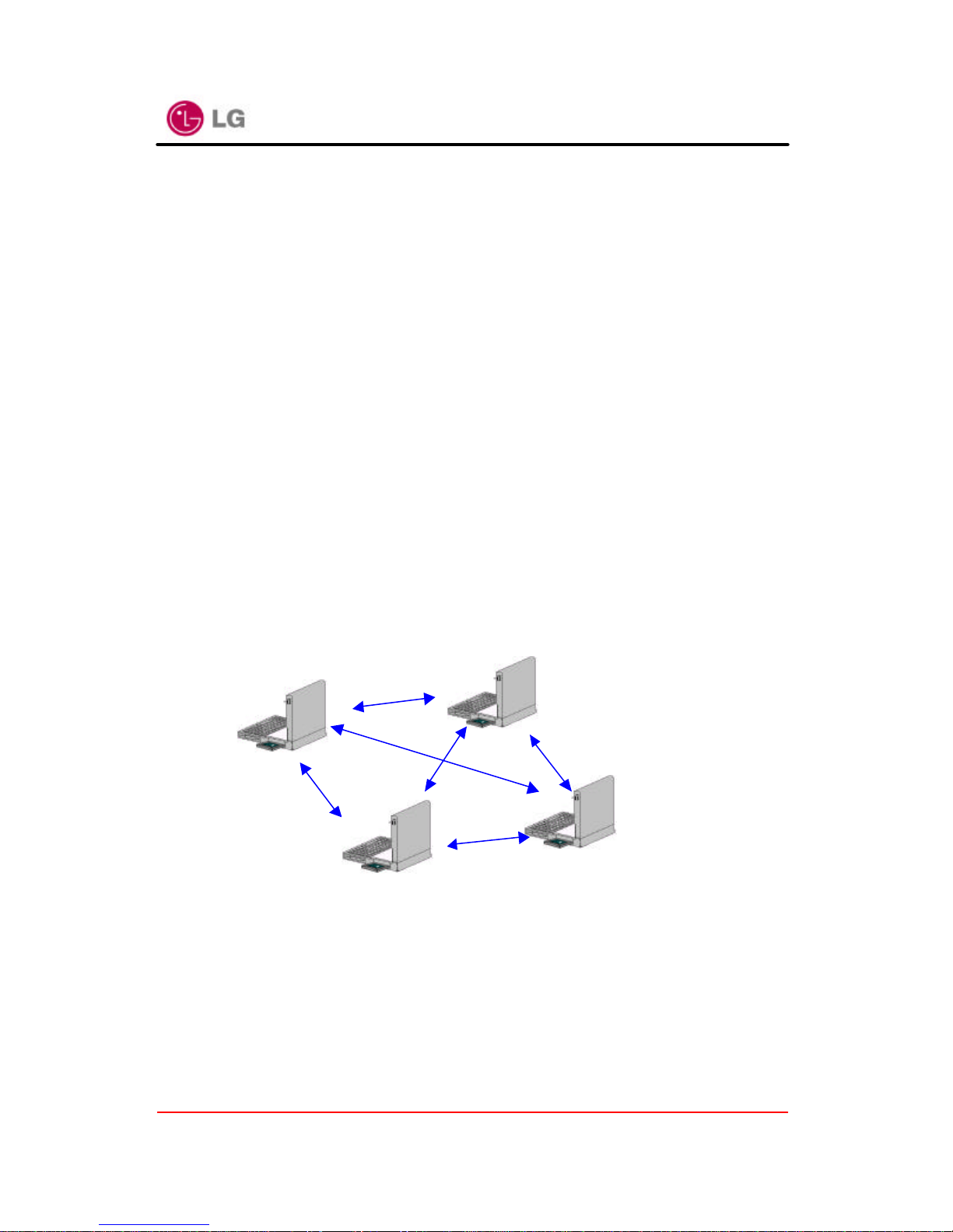
1.1 What’s Wireless LAN?
Wireless LANs use electromagnetic airwaves (radio and infrared) to communicate
information from one point to another without relying on any physical connection. Radio
waves areoften referred to as radio carriers because they simply perform the function of
delivering energy to a remote receiver. The data being transmitted is superimposed on
the radio carrier so that it can be accurately extracted at the receiving end. This is
generally referred to as modulation of the carrier by the information being transmitted.
Once data is superimposed (modulated) onto the radio carrier, the radio signal occupies
more than a single frequency, since the frequency or bit rate of the modulating
information adds to the carrier.
Multiple radio carriers can exist in the same space at the same time without interfering
with each other if the radio waves are transmitted on different radio frequencies. To
extract data, a radio receiver tunes in (or selects) one radio frequency while rejecting all
other radio signals on different frequencies.
In a typical WLAN configuration, a transmitter/receiver (transceiver) device, called an
access point, connects to the wired network from a fixed location using standard
Ethernet cable. At a minimum, the access point receives, buffers, and transmits data
between the WLAN and the wired network infrastructure. A single access point can
support a small group of users and can function within a range of less than one hundred

LG GoldStream
Page 6of39
to several hundred feet. The access point (or the antenna attached to the access point)
is usually mounted high but may be mounted essentially anywhere that is practical as
long as the desired radio coverage is obtained.
End users access the WLAN through wireless LAN adapters, which are implemented as
PC cards in notebook computers, or use PCI adapters in desktop computers. WLAN
adapters provide an interface between the client network operating system (NOS) and
the airwaves (via an antenna). The nature of the wireless connection is transparent to
the NOS.
1.2 Wireless LAN Standard and Structure
¦Wireless LAN Standard –IEEE802.11b
The widespread acceptance of WLANs depends on industry standardization to ensure
product compatibility and reliability among the various manufacturers. The Institute of
Electrical and Electronics Engineers (IEEE) ratified the original 802.11 specifications in
1997 as the standard for wireless LANs. That version of 802.11 provides for 1 Mbps and
2Mbps data rates and a set of fundamental signaling methods and other services. The
most critical issue affecting WLAN demand has been limited throughput. The data rates
supported by the original 802.11 standard are too slow to support most generalbusiness
requirements and have slowed adoption of WLANs. Recognizing the critical need to
support higher data-transmission rates, the IEEE recently ratified the 802.11b standard
(also known as 802.11 High Rate) for transmissions of up to 11 Mbps.
With 802.11b, WLANs will be able to achieve wireless performance and throughput
comparable to wired Ethernet.Outside of the standards bodies, wireless industry leaders
have united to form the Wire-less Ethernet Compatibility Alliance (WECA).
WECA’s mission is to certify cross-vendor interoperability and compatibility of IEEE
802.11b wireless networking products and to promote that standard for the enterprise,
the small business, and the home. Members include WLAN semiconductor
manufacturers, WLAN providers, computer system vendors, and software makers.
¦Wireless LAN Network Equipment
802.11 defines two pieces of equipment, a wireless station, which is usually a PC
equipped with a wireless network interface card (NIC), and an access point (AP), which
acts as a bridge between the wireless and wired networks. An access point usually

LG GoldStream
Page 7of39
consists of a radio, a wired network interface (e.g., 802.3), and bridging software
conforming to the 802.1d bridging standard. The access point acts as the base station
for the wireless network, aggregating access for multiple wireless stations onto the wired
network. Wireless end stations can be 802.11 PC Card, PCI.
¦Wireless LAN Network Configuration
The 802.11 standard define two modes: infrastructure mode and ad hoc mode (or
independent or peer-to-peer).
lAd Hoc Mode
Ad hoc mode (also called peer-to-peer mode or an Independent Basic
Service Set, or IBSS) is simply a set of 802.11 wireless stations that
communicate directly with one another without using an access point or any
connection to a wired network. This mode is useful for quickly and easily
setting up a wireless network anywhere that a wireless infrastructure does not
exist or is not required for services, such as a hotel room, convention center,
or airport, or where access to the wired network is barred (such as for
consultants at a client site).
Figure 1. Ad Hoc Mode
lInfrastructure Mode
In infrastructure mode, the wireless network consists of at least one access
IndependentBasic
Service Set (IBSS)

LG GoldStream
Page 8of39
point connected to the wired network infrastructure and a set of wireless end
stations. This configuration is called a Basic Service Set (BSS). An Extended
Service Set (ESS) is a set of two or more BSSs forming a single sub-network.
Since most corporate WLANs require access to the wired LAN for services
(file servers, printers, Inter-net links) they will operate in infrastructure mode.
Figure 2. Infrastructure Mode
¦Roaming
Wireless communication is limited by how far signals carry for given power output.
WLANs use cells, called microcells, similar to the cellular telephone system to extend
the range of wireless connectivity. At any point in time, a mobile PC equipped with a
WLAN adapter is associated with a single access point and its microcell, or area of
coverage. Individual microcells overlap to allow continuous communication within wired
network. They handle low power signals and “hand off” users as they roam through a
given geographic area.
The 802.11 MAC layer is responsible for how a client associates with an access point.
DistributionSystem(DS)
Service Set (SS) –Multiple
Access Point (AP)
Ethernet(802.3)

LG GoldStream
Page 9of39
When an 802.11 client enters the range of one ormore APs, it chooses an access point
to associate with (also called joining a Basic Service Set), based on signal strength and
observed packet error rates. Once accepted by the access point, the client tunes to the
radio channel to which the access point is set. Periodically it surveys all 802.11 channels
in order to assess whether a different access point would provide it with better
performance characteristics. If it determines that this is the case, it reassociateswith the
new access point, tuning to the radio channel to which that access point is set.
Reassociation usually occurs because the wireless station has physically moved away
from the original access point, causing the signal to weaken. In other cases,
Reassociation occurs due to a change in radio characteristics in the building, or due
simply to high network traffic on the original access point. In the latter case this function
is known as “load balancing,” since its primary function is to distribute the total WLAN
load most efficiently across the available wireless infrastructure. This process of
dynamically associating and reassociating with APs allows network managers to set up
WLANs with very broad coverage by creating a series of overlapping 802.11b cells
throughout a building or across a campus. To be successful, the IT manager ideally will
employ “channel reuse,” taking care to set up each access point on an 802.11 DSSS
channel that does not overlap with a channel used by a neighboring access point.
Figure 3. Roaming
Backbone Network
Access Point (AP)
Inter-Cell Roaming

LG GoldStream
Page 10of 39
¦BSS, ESS and SS ID
The basic service set (BSS) is the basic building block of WLAN network. Minimum
WLAN BSS may be consist of only two stations. Using access point (AP) and network
distribution systems (DS), WLAN service set can be extended arbitrary size –extended
service set (ESS). Each service set has its network ID (SSID). All the service sets within
an ESS network can have same service ID so that the ESS can support inter-cell
ROAMING.

LG GoldStream
Page 11of 39
Figure 4. SSID and Roaming
Backbone Network
AP #`2 SS ID
= LG
ROAMING
AP #`1 SS ID
= LG
AP #`3 SS ID
= Acro
ESS
BSS
Backbone Network
Re-Configuration
Required

LG GoldStream
Page 12of 39
Chapter 2 Before You Start GoldStream
To use the GoldStream adapter with a computing device (desktop personal computer,
notebook, laptop computer, portable or hand-held device), the device must be equipped
with an internal or external PC Card Type II or Type III slot. All drivers and supporting
software (card and socket services) for the client adapter slot must be loaded and
configured.
Ask your system administrator for the following information, which you may need to
provide during driver installation:
• Your Wireless Client Name
• Your Wireless SSID
•Your computer's unique client name and workgroup name
•For Windows NT, a free interrupt and I/O address.
• For your network account, your user name and password
• If you’re not using a DHCP server, your IP address, gateway address, and subnet
mask
After unpacking the card, make sure the following items are present and in good
condition:
•LG GoldStream LW1100 Series PC Card Adapter
•LW1100 Series install software and documentation CD for Windows 95 and Windows
98, 2000, ME.
If any item is damaged or missing, contact your PC Card adapter supplier. Save all the
shipping and the packing material to repack the unit should service be required.
Caution
Before you start, close all working windows and backup important data.

LG GoldStream
Page 13of 39
Chapter 3 Installing the PC/PCI Card Adapter on a Windows OS
This section provides instructions for installing a PC/PCI adapter on a computer using
one of the Windows operating systems.
Caution
The following procedures and physical connections apply generally to normal and
conventionalclient adapter slots. In the cases of custom or non-conventional equipment,
be alert to possible differences in client adapter slot configurations.
3.1 Installing PC Card Adapter
Before you begin, examine the client adapter. One end is a dual-row, 68-pin client
adapter connector. This side will be inserted into the client adapter slot with the logo on
the client adapter facing up. The card is keyed so it can be inserted only one way into
the slot.
The client adapter can be connected to a client adapter Type II slot. This includes slots
that support both Type II and Type III cards.
Caution
Do not force the client adapter into the slot. Forcing it will damage both the client adapter
and the slot. If the client adapter does not go in easily, remove thecardandreinsert it.

LG GoldStream
Page 14of 39
3.1.1 Installing the PC Card Driver for Windows Operating Systems
´Windows95, 98, 2000, ME
If the operating system on your computer is Windows, follow these steps.
If you insert the GoldStream software anddocumentation CD for Windows, the Windows
automatically runs GoldStream setup program and a dialog box appears.
If above dialog box does not appear, select CD-ROM drive, and click“setup.exe”file.
Click Next>icon. A License Agreement dialog box appears asking whether you agree
with the license or not.
If you agree, clickYes icon.
STEP 1
STEP 2

LG GoldStream
Page 15of 39
Give the destination folder. To set the path of your choice click on Browse and then click
Next.
STEP 3

LG GoldStream
Page 16of 39
Select the SSID. Default SSID is ANY. You can change this later using the configuration
utility or network configuration. Click on Next.
Select network type and click on Next. Default is infrastructure.
STEP 4
STEP 5

LG GoldStream
Page 17of 39
Confirm the current settings; SSID, Network Mode, Utility directory and click on Next.
STEP 6

LG GoldStream
Page 18of 39
It takes a few seconds for copying the utility files and then click on Finish to complete
the installation.
STEP 7

LG GoldStream
Page 19of 39
3.1.2 PC Card (PCMCIA) Network Configuration
If you have completed PC card installation, insert the PC card. If
you PC detects the PC card, you can find glittering LED and PC
sound. Also you will see the PC card icon on the right bottom of
your screen.
If you install LG’s wireless LAN card for the first time all the setup
process runs automatically. If you reinstall, the install program asks next two files folder
position and you should select same as the below:
File name Path
lgwlan.inf c:\windows\inf
cw10.sys c:\windows\system
And then the install program asks whether you want to reboot your computer. At this
time you should select Noin order to complete the installation correctly.
Click on My Computer icon. Select the Device manager and network adaptors. If you
find yellow (?) sign on the adaptor, it shows the installation is not successful. Select the
adaptor and click on Remove. Restart your computer after uninstalling the driver to
make the change effective.
Click on the Network Neighborhood using mouse and select properties from the pop up
menu. The network box appears and you see three main tabs; Configuration,
Identification, Access control.
Click on the configuration tab and then click on add button. Select network component
type box appears. Click on the protocol then click the add button.
Select network protocol box. Fromthe list of manufactures, click on Microsoft. From the
list of network protocols, select NetBEUI and click OK.
The NetBEUI protocol is now installed. After click on OK, return back to Network
Component Type box.
Repeat this protocol add procedure to add IPX/SPX protocol and TCP/IP protocol.

LG GoldStream
Page 20of 39
Caution
This Process could cause serious problem on your network if you edit wrong data. So, if you do
not know how to configure your network option, ask for help your network administrator.
Click on the TCP/IP option for setting the IP address for your computer. You can select either
Static or DHCP setting. If you use static IP address then enter the IP value assigned for you, and
Subnet masking, DNS, Domain/Workgroup name, Gateway address value.
This manual suits for next models
1
Table of contents
Other LG Adapter manuals
Popular Adapter manuals by other brands

Supermicro
Supermicro AOC-MH25G-b2S2G user guide

Parallax
Parallax XBee manual

Avaya
Avaya Avaya one-X Gigabit Ethernet Adapter Installation and safety instructions

Nvidia
Nvidia QUADRO SLI HB BRIDGE quick start guide

Mellanox Technologies
Mellanox Technologies ConnectX-3 Pro user manual

Planex
Planex URS-02 user manual