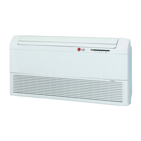
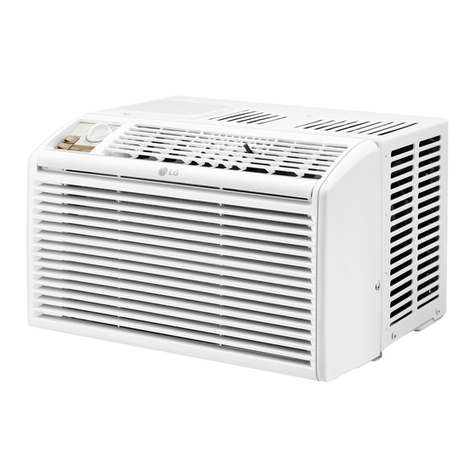
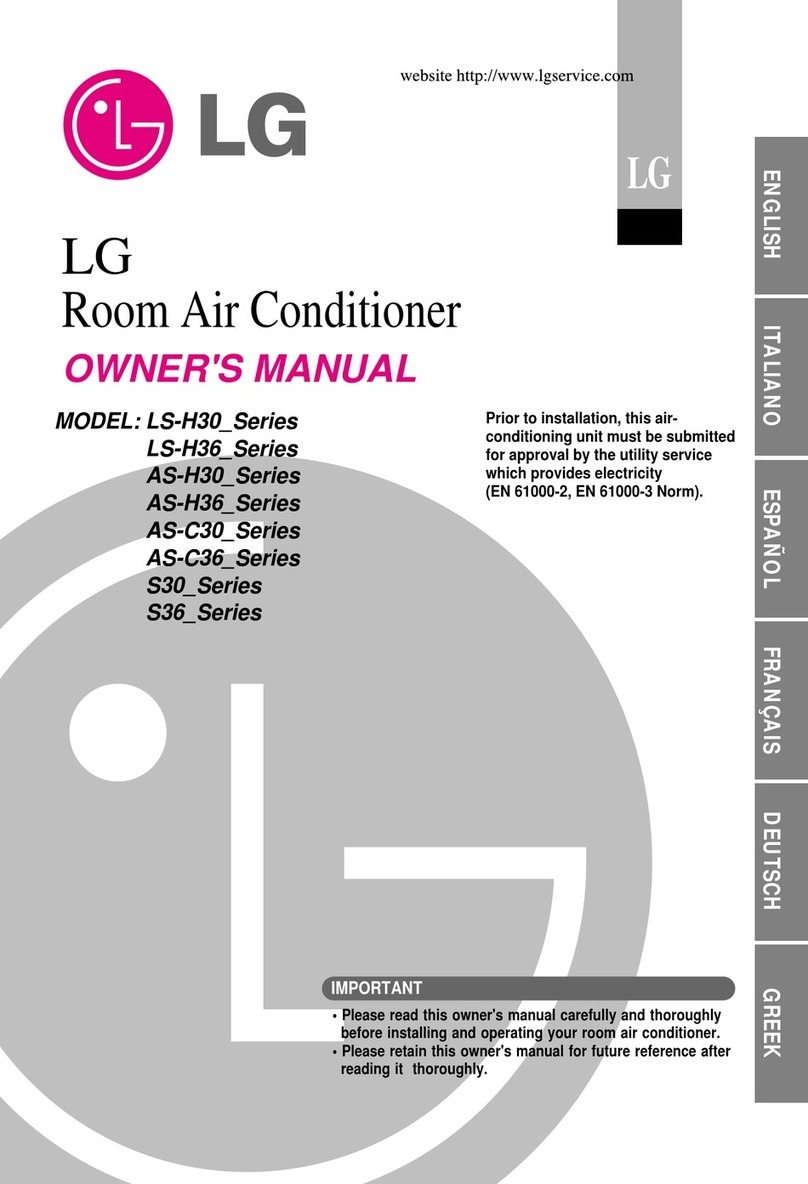
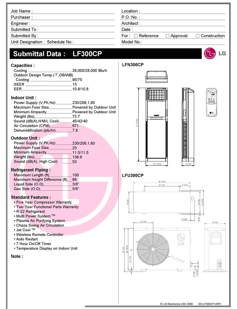
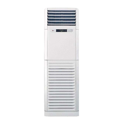
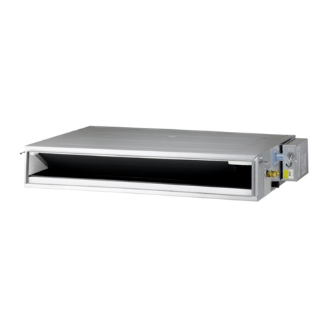
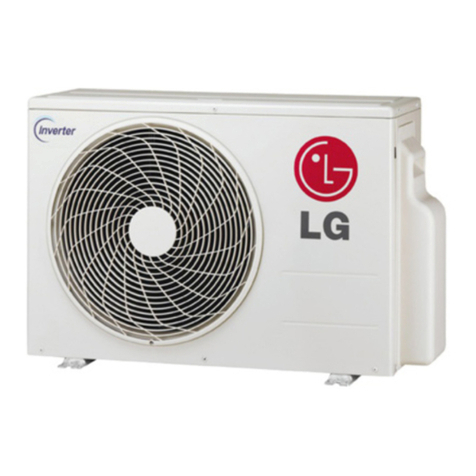
LG LT1030H User manual

website http://wwwJgservice.
e-mail ihttpJ/www.lgeser v:ice.i
L
P_ease read the operating in_ruc:tions and safety pr_autions carefully
and thoroughly before installling and operating your r_m air conditioner.
AIREDEVENTANA
le

FOR YOUR RECORDS
Write the model and serial numbers here:
Mode| #
Serial #
You can find them _l a _ab,e_on the side of each un_
D,ea_er's IName
Da_e Purchas_
lib Staple your rec÷ipt to this [page in the event yOLlneed it
to ipr_e _te of purchase or for warranty issues.
READ THIS MANUAL
hside you will find many _][pfu[ hints on how to use and
maintain your air conditio_r pro_rty. Just: a liitt[e pr_¢entive
care on _ur _t can _ve y_.J a great dea_ of time and
money over the _ifeof your air cond_ionero
You _11find many answers to. common problems in the chart
of troublesho_ing t:#s. _ifyou review our chart of
Troubleshooting Tips first, you may not _ed to ca_] for
serv_e at afl_
. Conlact the authorized _rvice technician for repair
or maintenance of this unit,
Contact the instal!_ for install_ion of _his u_ff,
•The air conditioner is not _n_ndee for use _young
children or invalids without supervision
Young chi|dten sho_|d be ss_rvis_ to ensure _hat
they do not p|ay wRh the air co=nditio_er,
, When the power cord _s f_o be replaced, replacement
_rk shah be _rformed by a_thoiriz_ personnel only
esing o_ly genuine ir_lacement parts.
• |nstallation wo_ musl; be performed i_ _rdance
w_h the National E|e_ric _de Iby q_a|iffi_ and
au_hor_z_ perso_ne| on|y;
2 Room Air Conditioner

To prevent injury to the user or other _opte and property damage, the following instructions
must be followed.
[] Incorrect operation due to ignoring instruction will cause harm or damage. The seriousness
is classifi_ by the following
iMeanings of symbols us_ in this manual are as shown below,
I 1
Be sure, not to ,do,.
Be sure to follow the instruction.
[] Installation
• Otherwise, it may cause a
fire or electrical shock
•It may _use _ilure and
el_ic sh_.
• Othe_ise, it may cause a
fire or electrical shock,
•Sharp edges may cause
injury.
• Itwilli cau_ e_ric _o_ or
fire due to heat _eration,
•it may _use ex#osion or
fire.
Owner_ Manual 3

II Operation
, There is danger of fire
el_ric shock. or • litwill cause elec_ic shock or
fire due to heat generation,. • Otherwise, it may cause
fire or electrical shock.
, _tmay cause fire and electric
shock. • litwill _use failure of machine
or electric shock. • The appearance of the air
_nditk_ner may deteriorate,
change color, Ordeve[op
surface flaws,
.Otherwise it:may cause fire
and e_ectricshock accident.
• An oxygen shortage may
OCCUr.
•Otherwise, it may electricali
shock and failure.
• Since _e fan rotates at high
s_ed during operation, _ may
cause injury,
, Prevent accidenta_sta_up and
the po_ibility of injury.
4 Room Air Conditioner

, it will cause electric shock:or
fire due to heat generation.
. It may cause electric shock
and damage.
[] Installation
. _ will cause electdc shock or
fire.
•Othe_ise, it may cause
explosion, and a fire.
*Otherwise, it:may cause dispute with the
neigh_rs.
* it will cause electric sho_.
• They are sharp and may
_use injury.
•Otherw[se, Jtmay cause vibration or water
leakage.
Owner_ Manual 5

[] Operation
• It may cause injury: • _tmay cause product failure. • The appearance of the air
conditioner may deteriorate,
change _lor, or develop
surface flaws.
• It may cause an injury
through dropping of the unit
or falling down.
•,it may _use injury:
• O_ration without filters will
cause failure
• Othe_ise, it may do harm
to your Ihealth.
, I_contains containments and
will make you sick.
6Room Air Conditioner
• Othe_ise, it may cause
perso hal inju ry.

Prior to Opera#on
1i' Contact an installation specialist for installation.
2. Plug in the power plug properly.
3. Use a dedicated circuit.
4. Do not use an extension cord.
5. IDo not startJstop operation by plugging/unplugging the power cord.
6;. If the cord/plug is damaged, replace litwith only an authorized replacement
part.
1i_ Being exposed to direct aidlo,w for an extended period of time could be
hazardous to your health, Do not expose occupants, pets, or plants to direct
airflow for extended periods of tiime.
2, Due to the possibility of oxygen deficiency, ventilate the room when used
together with stoves or other heating devices,
3 Do not use this air conditioner for non-specified special purposes (e.g.
preserving precision devices, rood, pets, plants, and art objects). Such usage
could damage the items,
1 Do not touch the metal parts of the unit when removing the filter Injuries can
occur when handling sharp metal edges.
2. Do not use water to clean inside the air conditioner. Exposure to water can
destroy the insulation, leading to possible electric shock.
3. When cleaning the unit, first: make sure that the power and breaker are turned
off:.The fan rotates at a very high speed during operation. There is a
possiibii]ity of injury if the unit's power is accidentally triggered ,onwhille
cleaning inner parts of the unit,
For repair and maintenance, contact your authorized service dealer,
Owner_ Manual 2'

Introduction
This symbol alerts you to the risk of electric shock.
This symbol alerts, you to hazards that could cause harm to
the air conditioner.
This symbol indicates specia! notes.
This @_iance sho,uld be installedin aocordance w_ the Naflona_ Electric C_e.
THE SLEEVE AND THE REAR GRILLE
(¢©tionally supp!i_ wi_hy_u_ u_}
SLEEVE ASSEMBLY
(Includihg A_um hUmReap grille}
REAR GRILLE
Real grille)
VERTICAL A!R DEFLECTOR
(Horizontal
THE UNIT
AIRF_LTER°-------_
NOR_ZONTAL AIR DEFLECTOR
(Ve_ticai Louver}:
VENT CONTROL
NR DISCHARGE
CABINET
F_DNT GRILLE
8 Room Air Conditioner

El_trical Safety
1!5V ~ 23,0W Power cord may include a current
inter_pter device. A test _d reset button is
provided on the plug c_e. The device
should _ tested on a pedodic basis, by firs_
pressing the TEST button and then the
RESET button, if the TEST button does not
trip or if the RESET button will not stay
engaged, discontinue use of the air
conditiioner and contact a qualified sewice
technici_.
The sha_ my be different acceding to its _L
Use Wall Recepta.c[e Power Supply
Standard 125V, 3-wire grounding
recep_cie _ated _SA, _25V AC
Standard 250V_ 3-wire grounding
rec®tacle rated 15A, 250,V AC
Standard 250V, 3-wire grounding
reci@tade rated 20A 250,V AC
Use 15 AMP t_me
delay fuse or 15 AMP.
circuit breaker.
Use 20 AMP t_me
delay fuse or 2,0 AMP
circuit breaker.
DO NOT USE AN EXTENSION CORD ® 230,
208 _ 230/2_ Vott uni_.
Alilwiri_ sh_lld be made in _o_dance with IocaJ
el_i_l c_s and r_ulatJons,
Aluminum _u_ wiring may p_e _ial
pr_l_s, Con_lt a qualifi._ ._ectrician,
A WARNING
Never push the test bL,_tonduring
Othe_i_ this p,lug can damaged,
This devk',e cor_tains chemical including
_ead, known to the State of C,alibmia to
cause can_r, a_,d birth de_ec'ts or ,other
reproductive harm,
Wash hands after han,d!ing,
Do _t remove, modify or immerse this plug
If this devi_ trips, the cause it to be
corrected _bre fu_er use,
A CAUTION
The conductors inside this cord are
surrounded by"shields, which monitor
leakage cu_ent.
These shields are not grounde&
<Made in Tower>
Periodi_lly examine the _rd for any
dam age, Do not use this produ_ in _e
event the shieMs become exposed.
Avoid shock: hazard, this unit can not
user serviced o_ning the tamer
resis_nt. Sea[edi potion of the unit
voids all warranties and _rformance
claim& This unit not intended for use
as an on-off switch.
Owner_ Manual 9

(PLEASE READ CAREFULLY)
FOR 'THE USER_ L SAFE_ THIS
APPLIANCE MUST BE PROPERLY GROUNDED
The power cord of this _p_iance is equipped with a
three-prong (grounding} plug, Use this with a etandard
threes_ot (grounding) wag power outlet to minimize the
hazard of electrc sh_;k, The customer should ha_ the
wal! r,e_ptacle and circuit checked by a qua!itied
e_ectfician to make sure the receptacle is propedy
NOT CUT OR RE_VE THE THIRD (GROUND)
PRONG FROM THE P_ER PLUG,
A. SITUATIONS WHENCE APPLIANCE WILL BE
DISCONNE_ED OCCASIONALLY:
Because of potential safety h_ards, we strongly
discourage the use of an adapte_ p_ug However, if you
wish to use an adapter° a TEMPORARY CONNEC"FION
may _ mad& Use UL-iisted adapter_ a_ilable from
most _al hardware stores
The large sbt in the adapter must _ a/ign_J with the
!arge slot: in the reoepta¢!e to assure a proper polarity
conn,ection,
: Attachi_ theadapCetgro,undlermtnal to thewall
r_eptac|e covetscrewdoes not:groundthe appliance
unless thecover'screwis _tal, and not:insulated,and
thewa|| receptacle isgroundedthroughthe house
'witing,_e ¢ustome_sho,uMh_e the circuitchoked
aqualifiedeleCt|clan to makesurethe r_ept_ie
is proper_ground&
Disconnect the power cord 'item the adapter_ using ,one
hand on each, Otherwise° the adapter ground termina_
might break. DO NOT USE _e appiiance with a broken
adapter plug.
B. SITUATIONSWHENCE APPLIANCE WILL BiE
DISC,ONNE_ED O_EN,i
__>not use an adapter p_ug in these situations,
Unplugging the [power c_rd frequently can _ead to an
eventual breakage of the ground terminal The wall
power outiet shouM be replaced by a three-slot
(grounding} out_et instead,
USE OF E,_ENS|ON CORDS
Because of potentia! safety hazards, we strongly
discourage the use of an _×tension cord Howe'_r_ if
you wish to use an extension ,cord, use a CSA
_rtifiedEUL-listed 3-wire (grounding) extension _rd,
rated at 15A, 125'7
10 Room Air Conditioner

Ins,tallatfon
Rerne_._packing sheet _rem1he back dthe sl_ve, and
packing corner and blue tape from the air con@J,oner.
INSTALLATION REQUIIREMEN
If you use an existing wall sl_ve, you should
measure its dimensions.
install the new _r conditioner according to these
installation ins#uctions to achieve the best
pedormance, All wall s_eeves used to mount the
new air _nditioner must be in good stru,cturat
condition and have a re_ grille to, securely attach
the, new air conditioner. (FIG. 1)
Witlh thie LGE s_eeve(opflonally supplied with your
unit), you _n main|ain the best performance of the
new air conditioner. (FIG. 2}
Air Conditio,ner FIG 1
F_,G,2
ELECTRICAL SE_ICE
Check your available ele_ri_l service. The _wer
su_ly availab_,e must: be the same as that shown
on the unE nameplate (found on left side of
INSTALLATION HARDWARE
ITEM NAME OF PA_S Q%Y
P_ST}C GRILLE 1
HORIZONTAL INSULAT!ON STR!PS 2
,_.£S}_=___AROUND INSULATIONSI"R_PS 2
SUPPORT8LOOK 2
_} BAFFLE 1
TRIM FRAME 2
SHIM 2
PLASTICNUTS _O WASHER SCREWS 4
(_) GRILLE REAR 1
Toa_id dsk dr_rsoral iqury, pr_y damage,or _@uct
damageduetothe weightdthisdwi@ and sharp_9es
that may _ expose:
•Air_ndiflon_s _._e_ in thisma_ualpose a_ exc_e
weight h_a_d Twoor more_le aren_ed/to m_e
a_din_aHthe unit.
ToFwent injuryor st[ails use preperI_i_g and carryisg
_hni,qu_ whe_ movi% un_.
• _rduily i_s_ct I,_tion whereair cer_itbner will
instalied _ sure itwill su_ t_ w_ght dthe unitove__
a_se£e_ded _.ri_ oftime.
• _ndle air ®nditi®e_ wi_hca_e'Wearp_o_e@veglo_es
whe_¢¢'erliftingolrcarryingthe unit, AVOIDthesharp
metalfins offront and rear c@s
• M_e sureak c_dit:ior_e__s notfall dud% installatbn.
AIIimodets are equipped with a 3°prong service
p_ug to provide proper service and safe _sitive
grounding. Do not change plug in any w@/. Do not
use ,an adapte__p_ug If your present wail! outlet does
not match your plug, ca!! a qualified electrician to,
make the necessary corrections. SAVE CARTON
for storage and th_ OWNER'S MANUAL for |uture
reference. The ,cation _ the best way to store unit
during _nt:er or when not in use.
REOUIRED TOOLS:
- Tight Fitting gloves
• Standard screwdriver
- Phiilllipsscrewdriiver
- Pliers
• Sharp, knife
• 3/8cinch ,open end
wrench o,radjustaMe
wrench
, l/4-inch hex socket
and ratchet
•Tape measure
, Hectdc drill
,1/4-inch driU bit
Owne, s Manual 11

Installation
INSTALLATION
CAUTION
We strongly recommend the removal of the
old wall sleeve and the installation of a new
LGE Wall Sleeve,
If you decide to keep the existing wall sleeve,
you have to redirect the louvers at the back of
the wall sleeve illustration. The use of pliers is
recommended. If you DO NOT redirect, you run
the risk of poor performance or product failure.
This is not covered under the terms of the LGE
warranty.
• Pick a location which will allow the conditioned air
to blow into the area you want. Good installation
with special attention to the proper position of the
unit will lessen the chance that service will be
needed.
ITEMS IN INSTALLATION HARDWARE
You may not need all parts in the kit. Discard
unused parts
ITEM (inches)
Plastic grille
Horizontal Insulation Strips
Around Insulation Strips
Support Block
Baffle
Shim
Trim Frame
Washer Screw
Nuts(Plastic)
Grille Rear
263/4 x 161/2
13/8x 5/8x 273/16
13/8x 13/8x 27%'t6
13/8x 3/4x 611/2
13/8x 13/8x 611/2
13/4 X 13/8 X 45/'16
14 x 41/2x %
13xl x3/4
Qty.
1
1
1
1
1
2
1
2
2
4
4
1
HOW TO INSTALL
E_ Identify the existing wall sleeve before
installing the unit from the listed below.
Brand
White-Westinghouse
Frigidaire
Carrier (52F series)
General Electric
iHotpoint
Wall Sleeve Dimensions (inches)
Width Height
25-1/2 15-1/4
26 15-5/8
Whirlpool 25-7/8 16-1/2
FeddersiEmerson 27 16-3/4
LGE 25-7/8 15-17/32
Emerson/Fedders 26-3/4 15-3/4
Carrier (51S Series) 25-3/4 16-7/8
Friedrich 27 16-3/4
Depth
16, 17-1/2
or 22
16-7/8
17-1/8
or 23
16-3/4
or 19-3/4
16-23/32
15
18-5/8
16-3/4
All wall sleeves used to mount the new Air
Conditioner must be in sound structural condition
and have a rear grille that securely attaches to
sleeve, or rear flange that serves as a stop for the
Air Conditioner,
_ emove old air conditioner from existing wall
sleeve.
_ lean the interior of an existing sleeve.
(Do not disturb seals.)
u all sleeve must be securely fastened in wall
before installing the air conditioner. Use the
nails or screws through sleeve into wall, if
needed. Repaint sleeve if needed.
_ repare the wall sleeve for installation of the
unit. If you plan to use your existing wall
sleeve, and it is not LGE, use procedure B or
C below.
Procedure
A
C
Brand
LGE
White-Westinghouse
Frigidaire Carrier
(52F series)
General Electric
iHotpoint
Whirlpool
Carrier (51S series)
Fedders/Emerson
EmersoniFedders
Friedrich
Depth(inches)
16-23/32
16, 17-1/2
or 22
16-7/8
17-1/8 or 23
18-5/8
16-3/4
or 19-3/4
15
16-3/4
r_ Install unit into wall sleeve.
new
&CAUTION
When installation is completed, replacement unit
MUST have a rearward slope as shown. To achieve
1.4" slope, remove the backing from the 11-13/16"
shim strips and attach them as shown below in Fig.
3. Place the higher portion of shim to the front of
the rib on base of wall sleeve.
1"h_gl_l--1 113/4"High
UNIT Wall Sleeve
SHIM PLACEMENT UNIT INSTALLATION
FIG. 3
12 Room Air Conditioner

lns_llation
PROCEDURE A
Bff you are using the ncw sleeve (optionally
supplied with y,our unit),skip to step :&
Otherwise, install the plastic grille from the kit,
Cut 'the plastic grille to 25o4/2" wide and 15-
1/4" h_h. Place the plastic gdHe to the inside
of the wall sleeve at the rear flange,
FIG_4,
FIG, 7
U]nstdl the new un& into the wa]li sleeve,
To assembJe trim, snap the t_ o,f each piece
into the, Mot of the other piece as shown beiew,
SWe trim ,over the front of the air conditioner
until trim iisflush with slleeve as shown _llow,
_ Fasten the 4 washer _rews to, secure the
grille to the wa_I sbeve, _fyou need plastic nuts
to mount pUastic grille to the inside of the wall
sle_e, there are plastic nuts in the ins_fl_bn
kit_The r_uts are installed from the inside of the
sleeve and are press_ into the square holes
o_the rear flanges,
of FiG. 5
_ emove the backing from the Ho,rizon_l
insulation strip lSs x s,,sx 27s_'_6and a_ach that
to the inside bottom of the siege as shown
_low: Remove the backing from the Around
Insulation strip IS,8 x s_,_x 6t _,,_and atlach that
to the inside front o! the sbeve as shown
_low.
FiG.6
_ emove the metai re__griiie and repiace it "_th
the p_asti,c rear gril!e to improve unit: er_ergy
efficiency,, The plastic grille r_Juc_s 'the amount
of hot air di_har_ that: r_ircu_ates through the
unit.
FIG. 8
ACAUTION
• Air co_itioners covered in _i:s manual _se
an excessive weight _zar& Two or more
peo_e are needed to move and install t_
unit,
To IFeven'_ iinjury or s_rain, use p=_aperli_Jng
and carrying techniques when moving unff,
and rear coils.
•Make sure air conditioner does not fall duriing
remova!,,
r _Owne, s Manual 13

Installation
PROCEDURE B
_edire_ the lieuvers at the back o| the wa_l
sleeve to 60 ° angle as shown in the FIG 9. The
use, ,o| pliers is re,®mmended,
RearLouvers
(Top View)
FI!G. '9
DRemove the backing from the Horizontal
Insulatbn strip 1_,8x 5,'_x 27_6 and attach that:
to the insNe bottom of the sleeve as sho_
below_ Remove the ba_ing from the A_o,und
Insulation strip 1_ x 3,,4x 61 _,_and at_ch that
to the ins_e front of '[he sl_ve as shown
below.
lf the walli sl_ve already has a rear grille, sNp
to sit_ 4. if the walli slieeve does net have a
rea_ gr[ib or Iouve_ p_ne], install! the plastic
grille from the kit, Cut the p,_asticgri_b to 25-
!/2" w_e and 15o!/4" high. Place the plastic
grille to the inside of the wall sl,e_o fatthe rear
Hange._
FiG. t2
_ emo'_ the metal rent gri!!e and replaoe it _th
the piasflc rear grille to improve unit .energy
efficiency The plastic grille re.du_s the amount
of hot air di_harge that r_ircu/ates through the
unit.
IF_'G.10 FIG. 13
_ asten the 4 washer sct-_s to secure the
grille to thie wall sleeve. If you need p,lastjic nuts
to mount plastic grille to the inside of the wall
sl_ve, there are plastic nuts in [hie instalfati,on
kit.The nuts are installed from the inside dthe
sl_ve and are pressed into the square hol_
of the rear f:liang¢_.
Fasten the scr_s FIG. t t
1:the depth of your existing wall s, lieer_e is less
than or equal to 18", skip to step 7. Othier_v_e,
cut the battles and the su_o.rt blocks
acco.rding to i.engthi "A '_in the table below.
_pth"D ' oftlheexisting
w,a!!s_ve (inches)
18 <D _<1,8°_:'_, s/4
19°_/_<D_ 22 4 IF_G,14
14 Room Air CoinditJoRer

lns_llation
PROCEDURE B
_ Remove the ba,_ing from the sup_rt b,[odts
and a_ach them to the inside of the wall sleeve
as shown HG !5, Slide the,baffle into slots of • Air co_itioners covered in this manual pose
Wall......................
Sie_e
Support
BIo_
FIG, 15
_ Unstall the new unit into the wall s_ee,ve.
unff.
To prevent injury ,orsitrain_use proper lifting
an8 caffying te&hniques when moving unil,
•When handling the air co,_iorar, be careful
to, avoid culs. from sharp meal fins.on kont
and rear coils,
, Make sure air conditioner do_ not fall during
removal.
To assemble trim, snap the *ab oil each pi_:e
into lhe s_ot o| _e ,o_er piece _ shown below.
SHde trim over the front ot the air conditioner
until trim is flush with s_eeve as shown _ow.
1
iiiiiiiiii
F_G.t6
Owne, s Manual 15

installation
PROCEDURE C
_ edir.ed the louvers at the back of the waB
sl_'ve to 60 ° angle as; shown in the FiG 17_
The use o! pliers is r_,mmendedo
RearLouvers
gO o
(Top View),
FIG, 17
lt the wdl sleeve dready has a rear grille, skip
to _ep 4, [Ifthe waB sleeve does not have a
rear grille or Iouvered panel, ins_l! the plastic
g_Ble from the k_ Cut: the [plastic grille to 26 °
lZ2" wide and 15o!/2" N,gh. P_ce the plastic
grille to the inside of the waB sl.eeve at _e rear
|lange_
DRemove the backing from the Horizontal
Insulation strip. !3,,8" x 13i/8i X 273/16 and attach
• at to, the _ns;i_ bottom of the sleeve, as
shown belo.w. Remo_ the backing from '[he
Around Insulation strip 13/8 x 13,/;, x 611/2 and
attach that to the inside front of the sleeve as
shown below
FIG_
If the depth of your exist:in9 sle,_e is le,_ than
or equal to t8 '_ skip to st_ 7. ,Othe_ise, cut
the barf,s and the sup_rt bk_ks ac_rdin 9 'to
Length "A" in the table below.
Place the plastic grille FIG, 18
_ asten the 4 washer screws to s_ure the
.9rBle to the wall ,sleeve. If you ne_ plastic nuts
to mount plastic griBe to the inside of the wall
sl_ve, there are plastic nuts in the instNlation
kit The nuts are instNl_ from the inside dthe
sleeve and arre p_essed into the square h,o[_
of the rear flange.
or
Fasten the screws FIG,. 19
Dep_'D" ofthe,exis_ng
18 <D :_<18_:_. _/4
1-_/4
4
_ emove the backing from the support blocks
and a_ach them to the inside of the wal!l sleeve
as shown FIG 22, ,Sli_ the baffle into slats of
the s_plport blocks
Wall
Sleeve
B_ock
FiG. 22
16 Room Air CoinditioRef

Ins_llation
PROCEDURE C
U Remove the b_ckin,9 from _e 13" shim strips
,and a_:ach them as shown below in FI9_24.
The higher port:ion o,f shim is to _ p,[a_d in
f_o,nt of the rib on the base of w,al! slee_,
_°high_I_l If _q,"High
FIG 23
FIG, 24
_ Removethe metai grilie and repiace it _th
rear
the £_asti,crear'gril!e to improve unit energy
efficiency.The £1asticgrille redu_s the amount
of hot _r discharge that r_ircWates through the
unit.
To assemble triim_ snap the tab of each piece
into the slot of the othe_ piece as shown belo,w,,
SIMe trim over the front of the air conditioner
until trim is flush with sl_ve as shown below,
Wall
FIG 26
FIG 25
_ IlnstaB the n_ unit into the wall sleeve
ACAUTION
•Air coinditio_rs cover_ inthis manua_ po_
uniL
To pr._ent injuryor strain, use prope.r JiBing
and carrying techniques when moving unit..
When, handlir_ the air co,_itio_r, be _refu_
to avoid cuts from sharp me_l 'fins on front
and rear coils.
Make sure air conditioner do_ n,_ fail duri_
removal,
Owne, s Manual 17

Operating instructions
The controls will look like one of the following:
OOff
Fan
Low Cool
High Coo_
Low Heat
( 0 ) :Turns the air conditiioner off,
( 0 ) :The low fan speed operation without cooling
(heating).
( _ ) :_ing 'with the I,_ spe_ _n _ion.
( _ ) :Cooling with the high spe_ fan _eratbn,
( _ ) ::Heating with the low speed f&q operatior_.
High Heat ( _ ) :Heating _th t_ high sp_ _n _eration,
Turn_e therm_t co_ro_ to the _sired _ttJng, _ central p_tion
is a _mal _.tflng for avera_ c_d_i_. Y_ can c_nge this _tt#t_0
if necessary, in a,ccordan_ w_ y_Jr temperature prelerence.
_e therm_at aut_aflcal_y controls c_ing _ healtjng_b,_ the fan
ru_ contin_._y w_r_ver the air con,ditioner is in _erati,_, If t_
room is too warm, turn t_ therm_tat control dockwi_, If 'the room B.
too c_li, turn the _ermostat cr__trotc_nterc_k_.
O_l,er
.THE AIR CONDITIONER
_is aut_ati_lly co,roB tff_ tem_rature dthe
in_r air.
The compressor will turn on a_ off to keep _ room
at the setti_ tem_rature.
In t_ heating _erati_, the e_ct_ _ater wi[[ turn
and off to k_p the room at the settin,g
temperature.
. HEAT PUMP MODELS
When the _tdoo_ tem_rature is I_,_erthan
-.4_ (24_), the .e_ectricheater will turn on instead of
the heat pump.
CAUTION
When _e air conditior_r has _e_ per_rmed its
cooling or heating _erati_ and is turned off o_
set:to the fan pociti_, wait at [ea_ 3 minutes
bebre resetting to the cooling operation again.
A slight heat: odor may come from the unit
when fir_ switching to HEAT after the
cooling season is ,over.This odor, caused
by fine dust: particles on the heater, wi[[
di_ppear quickly. This is harmless
18 Room Air Conditioner

Operating instructions
Add_io,nal controls and important information,
Push the ]everto,the "CLOSE"' position to,cool, heat or
recircu[ate room air only.
Pull the [everto the "OPEN" position to .exhaustsmoke or
stale air from the room,
This feature is_st us_ in conjunction with the FANONLY
_siflon.
The direction of air can _ controlled by adjusting the horizo,ntal
and vertical louvers,
i
PULL OPEN /PUSH CLOSE
• HORIZONTAL AIR-DIRECTION CONTROL
The horizontal air direction is adjusted by moving the vertical
io,uver.
The lever for the verti,ca_ louver is Io_ted in the right and left s,i,dle
of the air di_h,arge_
. VERTICAL AIR-DIRECTION CONTROL
The vertical air direction is adjusted by movingi the horizon_l
Io,uver.
Owner_ Manual 19

Maintenance and Service
TURNTHEAIR CONDITIONEROFFAND REMOVETHEPLUGFROM THEPOWEROUTLET
The air filter should be ch_k_ at least _ice a month _oi s_ if cleaning is
n_essary. Trap_d _rticles in the filter will build up and Nock the airflow,
This reduces the _oling capaci_ and also _uses an accumulation of
frost on the _oling coils.
if the filter becomes _rn or damaged you should replace immediately.
Replacement filters are availaNe from your salesperson, dea_er, and the
au_o, fized customer service centers.
1. Open the inlet grille downward by pulling out the top 0f the inlet gr[!le,
2. Remove the air filter from the front grille assembly by pulling the air
filter up slightly,
3. Wash _e filter using lukewarm water below 40_ (104_).
4. Gently shake the excess water from me filter completeliy.Replace the
filter,
The front grille can be removed for cleaning or to check the model and serial numbers.
For your safety, you should attach the _ont grille as the fo,]lowing pr_edures.
1. Pull down front grille from the cabinet top,.
2. Push front gri]le's tips toward the cabinet in
order to insert front gfille's tabs into, the
cabinet.
3. Open the inlet grille.
4. Tighten the screw _rough _e front gdl_e into
the plate of control box.
5. Close inlet gdHe.
20 Room Air Conditioner
This manual suits for next models
1
Table of contents
Other LG Air Conditioner manuals

LG
LG CL09F Quick start guide

LG
LG AS-W243DGY9(LSN240HSV2) User manual

LG
LG JRNU28GBGA4 User manual

LG
LG ARNU093BHA2 User manual
![LG ATNH24GPLED[UT24 NPD] User manual LG ATNH24GPLED[UT24 NPD] User manual](/data/manuals/28/2/282om/sources/lg-atnh24gpled-ut24-npd-air-conditioner-manual.jpg)
LG
LG ATNH24GPLED[UT24 NPD] User manual

LG
LG Multi V ARNU183NJA2 User manual

LG
LG TSG0 User manual

LG
LG PQRCVSL0QW User manual

LG
LG LP091HEM-Y8 User manual

LG
LG LWHD1009R User manual