4
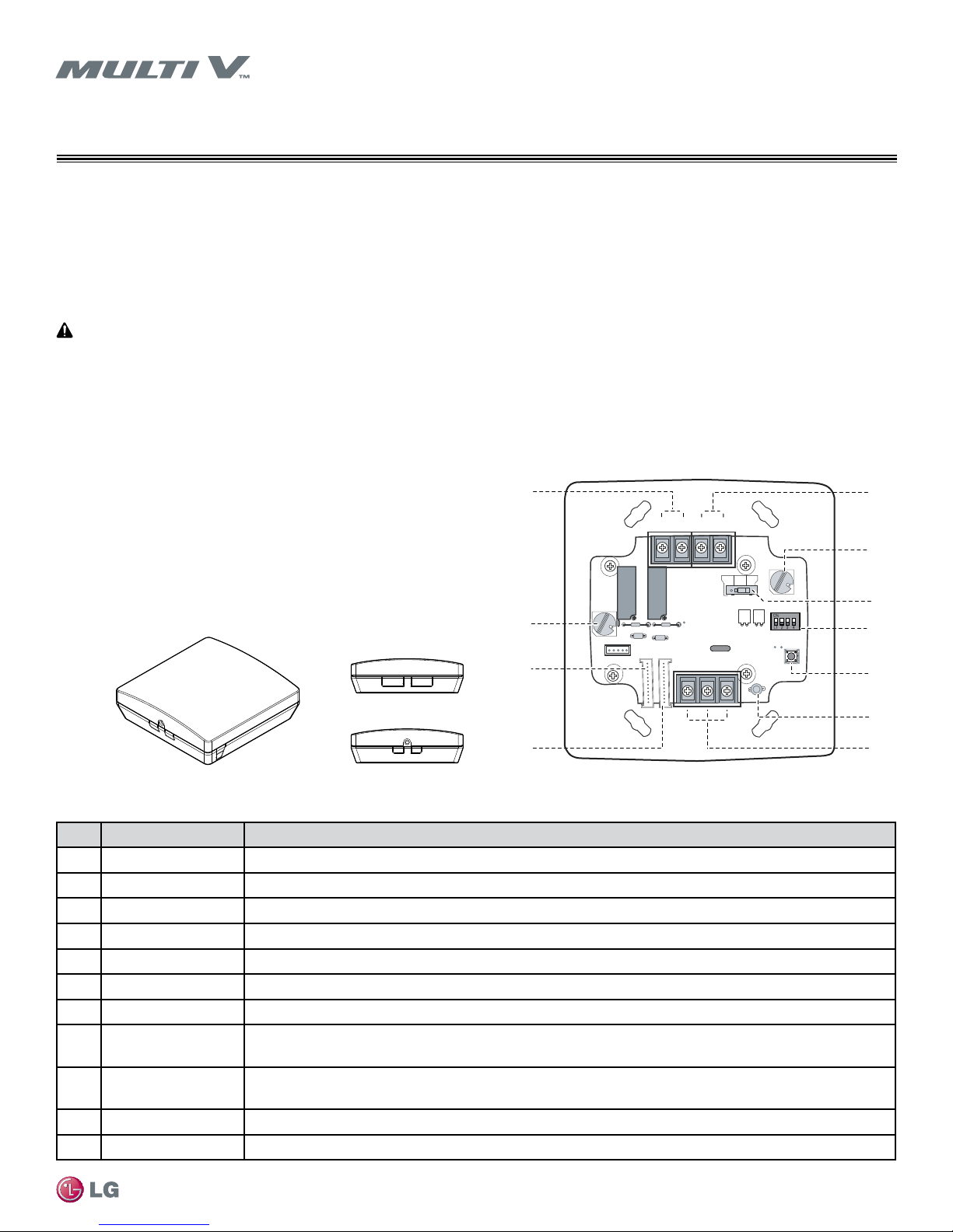
Dry Contact for Economizer
Due to our policy of continuous product innovation, some specifications may change without notification.
©LG Electronics U.S.A., Inc., Englewood Cliffs, NJ. All rights reserved. “LG” is a registered trademark of LG Corp.
The instructions below must be followed to prevent product malfunction, property damage, injury or death to the user or other people.
Incorrect operation due to ignoring any instructions will cause harm or damage. The level of seriousness is classified by the symbols
described below.
SAFETY PRECAUTIONS
This symbol indicates that the action or lack thereof could possibly cause death or personal injury.
This symbol indicates that the following action should not be performed.
This symbol indicates that the action or lack thereof could possibly cause equipment malfunction or failure.
Do not install, remove, or re-install the unit by yourself
(customer). Ask the dealer or an authorized technician to
install the unit.
Improper installation by the user may result in water leakage, re,
explosion, electric shock, physical injury or death.
For replacement of an installed unit, always contact an
authorized LG service provider.
There is risk of re, electric shock, explosion, and physical injury or
death.
Do not install the unit outside or in any location exposed to
rain. Do not install the unit in a humid location or a location
exposed to open ame or extreme heat. Do not touch the unit
with wet hands.
There is risk of re, electric shock, explosion, and physical injury or
death.
Dispose the packing materials safely.
Tear apart and throw away plastic packaging bags so that children may
not play with them and risk suffocation and death.
Do not store or use ammable gas or combustibles near the
unit. Do not install the unit in a location that generates oil,
steam, salt, sulfuric acid, etc.
There is risk of product failure, re, explosion, and physical injury or
death.
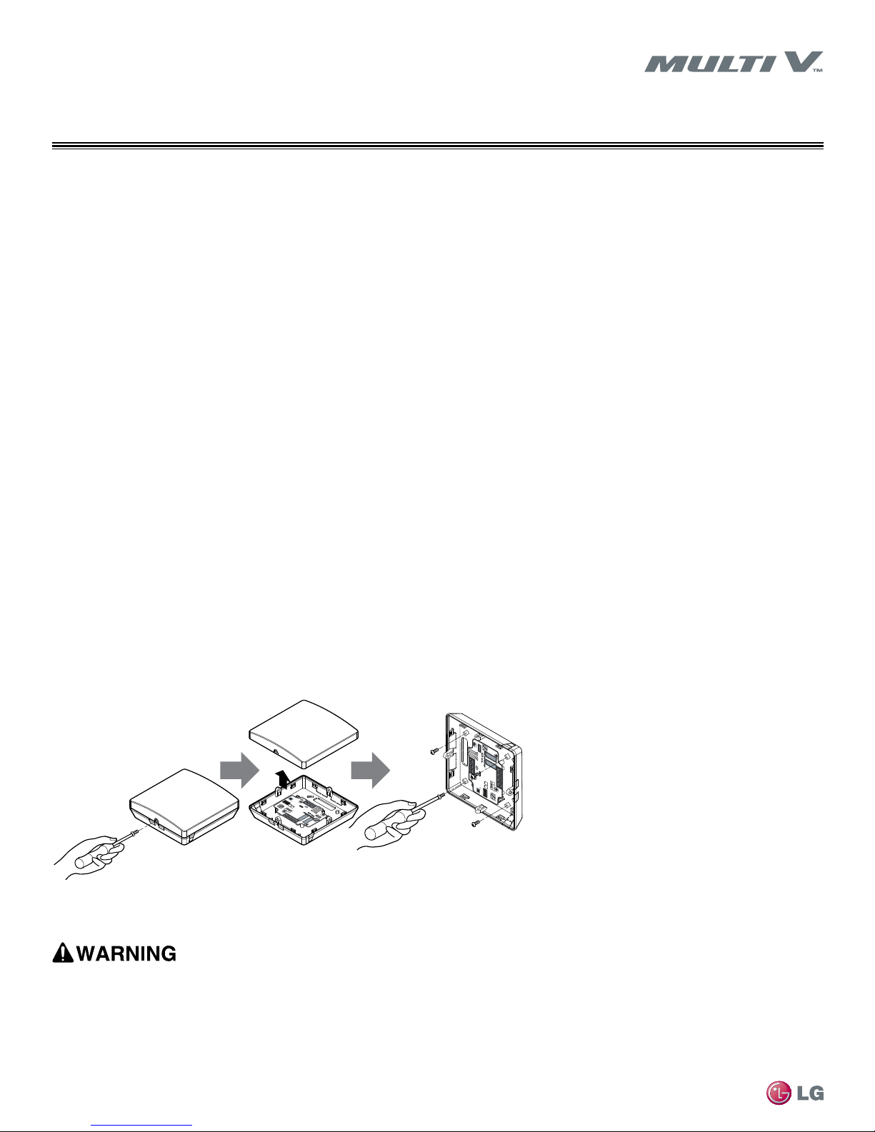
Replace all control box and panel covers.
If cover panels are not installed securely, dust, water or other foreign ob-
jects may enter the interior of a disassembled unit, causing re, electric
shock, and physical injury or death.
The information contained in this manual is intended for use
by an industry-qualied, experienced, certied electrician
familiar with the U.S. National Electric Code (NEC) who is
equipped with the proper tools and test instruments.
Failure to carefully read and follow all instructions in this manual can
result in equipment malfunction, property damage, personal injury or
death.
All electric work must be performed by a licensed electrician
and conform to local building codes or, in the absence of
local codes, with the National Electrical Code, and the
instructions given in this manual.
If the power source capacity is inadequate or the electric work is not
performed properly, it may result in re, electric shock, physical injury or
death.
Do not cut, lengthen or shorten the communications and
power cable between the dry contact unit and its connected
indoor unit. Do not install the unit in a location where the
communications and power cable cannot be safely and easily
connected between the two units. Do not allow strain on this
cable.
Ensure no power is connected to the unit other than as
directed in this manual. Remove power from the unit before
removing or servicing the unit.
Do not spill water inside of the unit or drop the unit into
water. If the unit is immersed in water or other liquid, contact
your dealer for support.
This unit and its associated air conditioning system are
intended for comfort air conditioning only. Do not use for
mission critical applications such as preserving food, ora
and fauna, precision instruments or works of art.
Turn the power off at the nearest disconnect before servicing
the equipment.
Electrical shock may cause physical injury or death.
Do not supply power to the unit until all installation and pre-
commissioning tasks are complete and the commissioning
agent indicates it is safe to do so.
Clean up the site after servicing is nished, and check that
no metal scraps, screws, or bits of wiring have been left
inside or surrounding the unit.


 null")