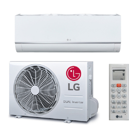
LG LW1223HRSM User manual

CAUTION
Room Air Conditioner
SVC MANUAL(Exploded View)
MODEL : LW1223HRSM
Before Servicing the unit, read the safety precautions in General SVC manual.
Only for authorized service personnel.
CONFIDENTIAL
Copyright © 2022-2023 LG Electronics Inc. All rights reserved. Only training and service purposes.
Any reproduction, duplication, distribution (including by way of email, facsimile or other electronic means),
publication, modification, copying or transmission of this Service Manual is STRICTLY PROHIBITED
unless you have obtained the prior written consent of the LG Electronics entity from which you received this
Service Manual. The material covered by this prohibition includes, without limitation, any text, graphics or logos
in this Service Manual.

Safety Precautions
To prevent injury to the user or other people and property damage, the following instructions must
be followed.
■Incorrect operation due to ignoring instruction will cause harm or damage. The seriousness is
classified by the following indications.
■Meanings of symbols used in this manual are as shown below.
WARNING
CAUTION
This symbol indicates the possibility of death or serious injury.
This symbol indicates the possibility of injury or damage to property only.
WARNING
■Installation
Do not use damaged power cord plugs, or a
loose socket.
•There is risk of fire or electric shock.
Always use the power plug and socket with
the ground terminal.
•There is risk of electric shock.
Be sure not to do.
Be sure to follow the instruction.
2Copyright © 2022-2023 LG Electronics Ins.
All right reserved.Only training and service purposes.
Safety Precautions

3Copyright © 2022-2023 LG Electronics Ins.
All right reserved.Only training and service purposes.
Safety Precautions
Do not modify or extend the power cord.
•There is risk or fire or electric shock.
Do not install, remove, or re-install the unit by
yourself(customer).
•There is risk of fire, electric shock, explosion, or injury.
Be cautious when unpacking and installing
the product.
•Sharp edges could cause injury. Be especially careful
of the case edges and the fins on the condenser and
evaporator.
Do not store or use flammable gas or com-
bustibles near the air conditioner.
•There is risk of fire or failure of product.
Be sure the installation area does not deterio-
rate with age.
•If the base collapses, the air conditioner could fall with
it, causing property damage, product failure, and per-
sonal injury.
Gasolin
Sharp edges

●Keep any required ventilation openings clear of obstruction.
●Prior to beginning work on systems containing flammable refrigerants, safety checks are necessary to ensure
that the risk of ignition is minimised. For repair to the refrigerating system, the following precautions shall be
complied with prior to conducting work on the system.
●Compliance with national gas regulations shall be observed.
IMPORTANT SAFETY INSTRUCTIONS
WARNING
WARNING
To reduce the risk of explosion, fire, death, electric shock, scalding or injury to persons, follow basic
precautions, including the following:
Checks to the area
●Work shall be undertaken under a controlled procedure so as to minimise the risk of a flammable gas or
vapour being present while the work is being performed.
Work procedure
●All maintenance staff and others working in the local area shall be instructed on the nature of work being
carried out. Work in confined spaces shall be avoided. The area around the workspace shall be sectioned off.
Ensure that the conditions within the area have been made safe by control of flammable material.
General work area
●The area shall be checked with an appropriate refrigerant detector prior to and during work, to ensure the
technician is aware of potentially flammable atmospheres. Ensure that the leak detection equipment being
used is suitable for use with flammable refrigerants, i.e. non-sparking, adequately sealed or intrinsically safe.
Checking for presence of refrigerant
●If any hot work is to be conducted on the refrigeration equipment or any associated parts, appropriate fire
extinguishing equipment shall be available to hand. Have a dry powder or CO2 fire extinguisher adjacent to
the charging area.
Presence of fire extinguisher
●This appliance is not intended for use by persons (including children) with reduced physical,sensory or mental
capabilities, or lack of experience and knowledge, unless they have been given supervision or instruction
concerning the use of the appliance by a person responsible for their safety. Children should be supervised
to ensure that they do not play with the appliance.
●If the supply cord is damaged, it must be replaced by the manufacturer, its service agent or similarly qualified
person in order to avoid a hazard.
●Do not use means to accelerate the defrosting process or to clean, other than those recommended by the
manufacturer.
●The appliance shall be stored in a room without continuously operating open flames (for example an operating
gas appliance) and ignition sources (for example an operating electric heater).
●Servicing shall only be performed as recommended by the equipment manufacturer. Maintenance and repair
requiring the assistance of other skilled personnel shall be carried out under the supervision of the person
competent in the use of flammable refrigerants.
●The appliance shall be stored so as to prevent mechanical damage from occurring.
●Do not pierce or burn. Be aware that flammable refrigerants may not contain an odor.
●The appliance shall be stored in a well-ventilated area where the room size corresponds to the room area as
specified for operation.
●Any person who is involved with working on or breaking into a refrigerant circuit should hold a current valid
certificate from an industry-accredited assessment authority, which authorises their competence to handle
refrigerants safely in accordance with an industry recognised assessment specification.
If you want to know information of installation, Read Installation Manual.
Mechanical connections (mechanical connectors or flared joints) shall be accessible for maintenance purposes.
●
●
4Copyright © 2022-2023 LG Electronics Ins.
All right reserved.Only training and service purposes.
Safety Precautions

●No person carrying out work in relation to a refrigeration system which involves exposing any pipe work that
contains or has contained flammable refrigerant shall use any sources of ignition in such a manner that it may
lead to the risk of fire or explosion. All possible ignition sources, including cigarette smoking, should be kept
sufficiently far away from the site of installation, repairing, removing and disposal, during which flammable
refrigerant can possibly be released to the surrounding space. Prior to work taking place, the area around the
equipment is to be surveyed to make sure that there are no flammable hazards or ignition risks.
“No Smoking” signs shall be displayed.
No ignition sources
●Ensure that the area is in the open or that it is adequately ventilated before breaking into the system or
conducting any hot work. A degree of ventilation shall continue during the period that the work is carried out.
The ventilation should safely disperse any released refrigerant and preferably expel it externally into the
atmosphere.
Ventilated area
●Where electrical components are being changed, they shall be fit for the purpose and to the correct
specification. At all times the manufacturer’s maintenance and service guidelines shall be followed. If in doubt
consult the manufacturer’s technical department for assistance.
●The following checks shall be applied to installations using flammable refrigerants:
– The actual refrigerant charge is in accordance with the room size within which the refrigerant containing
parts are installed.
●Initial safety checks shall include:
– Capacitors are discharged: this shall be done in a safe manner to avoid possibility of sparking.
– No live electrical components and wiring are exposed while charging, recovering or purging the system.
– Continuity of earth bonding.
– The ventilation machinery and outlets are operating adequately and are not obstructed.
– If an indirect refrigerating circuit is being used, the secondary circuit shall be checked for the presence
of refrigerant.
– Marking to the equipment continues to be visible and legible. Markings and signs that are illegible shall be
corrected.
– Refrigeration pipe or components are installed in a position where they are unlikely to be exposed to any
substance which may corrode refrigerant containing components, unless the components are constructed of
materials which are inherently resistant to being corroded or are suitably protected against being so corroded.
Checks to the refrigeration equipment
●During repairs to sealed components, all electrical supplies shall be disconnected from the equipment being
worked upon prior to any removal of sealed covers, etc.
●Particular attention shall be paid to the following to ensure that by working on electrical components, the
casing is not altered in such a way that the level of protection is affected.
●This shall include damage to cables, excessive number of connections, terminals not made to original
specification, damage to seals, incorrect fitting of glands, etc.
●Ensure that apparatus is mounted securely.
●Ensure that seals or sealing materials have not degraded such that they no longer serve the purpose of
preventing the ingress of flammable atmospheres.
●Replacement parts shall be in accordance with the manufacturer’s specifications.
●If it is absolutely necessary to have an electrical supply to equipment during servicing, then a permanently
operating form of leak detection shall be located at the most critical point to warn of a potentially hazardous
situation.
Repairs to sealed components
●Repair and maintenance to electrical components shall include initial safety checks and component inspection
procedures. If a fault exists that could compromise safety, then no electrical supply shall be connected to the
circuit until it is satisfactorily dealt with. If the fault cannot be corrected immediately but it is necessary to
continue operation, an adequate temporary solution shall be used. This shall be reported to the owner of the
equipment so all parties are advised.
Checks to electrical devices
5Copyright © 2022-2023 LG Electronics Ins.
All right reserved.Only training and service purposes.
Safety Precautions

●When breaking into the refrigerant circuit to make repairs – or for any other purpose – conventional procedures
shall be used. However, it is important that best practice is followed since flammability is a consideration.
The following procedure shall be adhered to:
– Remove refrigerant.
– Ensure that contamination of different refrigerants does not occur when using charging equipment. Hoses or
lines shall be as short as possible to minimise the amount of refrigerant contained in them.
– Cylinders shall be kept upright.
– Ensure that the refrigeration system is earthed prior to charging the system with refrigerant.
– Label the system when charging is complete (if not already).
– Extreme care shall be taken not to overfill the refrigeration system. Prior to recharging the system it shall be
pressure tested with OFN. The system shall be leak tested on completion of charging but prior to
commissioning. A follow up leak test shall be carried out prior to leaving the site.
– Purge the circuit with inert gas.
– Evacuate.
– Purge again with inert gas.
– Open the circuit by cutting or brazing.
●Do not apply any permanent inductive or capacitance loads to the circuit without ensuring that this will not
exceed the permissible voltage and current permitted for the equipment in use.
●Intrinsically safe components are the only types that can be worked on while live in the presence of a flammable
atmosphere.
●The test apparatus shall be at the correct rating.
●Replace components only with parts specified by the manufacturer.
●Other parts may result in the ignition of refrigerant in the atmosphere from a leak.
Repair to intrinsically safe components
●Cabling will not be subject to wear, corrosion, excessive pressure, vibration, sharp edges or any other adverse
environmental effects. The check shall also take into account the effects of ageing or continual vibration from
sources such as compressors or fans.
Cabling Check
●Under no circumstances shall potential sources of ignition be used in the searching for or detection of
refrigerant leaks. A halide torch (or any other detector using a naked flame) shall not be used.
Detection of flammable refrigerants
●The following leak detection methods are deemed acceptable for systems containing flammable refrigerants.
●Ensure that the detector is not a potential source of ignition and is suitable for the refrigerant used.
●If a leak is suspected, all naked flames shall be removed/extinguished.
●Oxygen free nitrogen (OFN) shall then be purged through the system both before and during the brazing process.
●The refrigerant charge shall be recovered into the correct recovery cylinders. The system shall be “flushed” with
OFN to render the unit safe. This process may need to be repeated several times. Compressed air or oxygen
shall not be used for this task. Flushing shall be achieved by breaking the vacuum in the system with OFN and
continuing to fill until the working pressure is achieved, then venting to atmosphere, and finally pulling down to a
vacuum. This process shall be repeated until no refrigerant is within the system. When the final OFN charge is
used, the system shall be vented down to atmospheric pressure to enable work to take place. This operation is
absolutely vital if brazing operations on the pipe-work are to take place. Ensure that the outlet for the vacuum
pump is not close to any ignition sources and there is ventilation available.
●If a leakage of refrigerant is found which requires brazing, all of the refrigerant shall be recovered from the
system, or isolated (by means of shut off valves) in a part of the system remote from the leak.
●Leak detection fluids are suitable for use with most refrigerants but the use of detergents containing chlorine
shall be avoided as the chlorine may react with the refrigerant and corrode the copper pipe-work.
●Leak detection equipment shall be set at a percentage of the LFL of the refrigerant and shall be calibrated to the
refrigerant employed and the appropriate percentage of gas (25 % maximum) is confirmed.
●Electronic leak detectors shall be used to detect flammable refrigerants, but the sensitivity may not be adequate,
or may need re-calibration. (Detection equipment shall be calibrated in a refrigerant-free area.)
Leak detection methods
Removal and evacuation
●In addition to conventional charging procedures, the following requirements shall be followed.
Charging procedures
6Copyright © 2022-2023 LG Electronics Ins.
All right reserved.Only training and service purposes.
Safety Precautions

●Before carrying out this procedure, it is essential that the technician is completely familiar with the equipment
and all its detail.
●It is recommended good practice that all refrigerants are recovered safely.
●Prior to the task being carried out, an oil and refrigerant sample shall be taken in case analysis is required
prior to re-use of reclaimed refrigerant. It is essential that electrical power is available before the task is
commenced.
a) Become familiar with the equipment and its operation.
b) Isolate system electrically.
d) Pump down refrigerant system, if possible.
f ) Make sure that cylinder is situated on the scales before recovery takes place.
g) Start the recovery machine and operate in accordance with manufacturer's instructions.
h) Do not overfill cylinders. (No more than 80 % volume liquid charge).
i ) Do not exceed the maximum working pressure of the cylinder, even temporarily.
k) Recovered refrigerant shall not be charged into another refrigeration system unless it has been cleaned
and checked.
j ) When the cylinders have been filled correctly and the process completed, make sure that the cylinders
and the equipment are removed from site promptly and all isolation valves on the equipment are closed off.
e) If a vacuum is not possible, make a manifold so that refrigerant can be removed from various parts of
the system.
c) Before attempting the procedure ensure that:
• mechanical handling equipment is available, if required, for handling refrigerant cylinders;
• all personal protective equipment is available and being used correctly;
• the recovery process is supervised at all times by a competent person;
• recovery equipment and cylinders conform to the appropriate standards.
Decommissioning
●Equipment shall be labelled stating that it has been de-commissioned and emptied of refrigerant. The
label shall be dated and signed. Ensure that there are labels on the equipment stating the equipment
contains flammable refrigerant.
Labelling
●When removing refrigerant from a system, either for servicing or decommissioning, it is recommended
good practice that all refrigerants are removed safely.
●When transferring refrigerant into cylinders, ensure that only appropriate refrigerant recovery cylinders are
employed. Ensure that the correct number of cylinders for holding the total system charge are available.
All cylinders to be used are designated for the recovered refrigerant and labelled for that refrigerant
(i.e. special cylinders for the recovery of refrigerant). Cylinders shall be complete with pressure relief valve
and associated shut-off valves in good working order. Empty recovery cylinders are evacuated and, if
possible, cooled before recovery occurs. The recovery equipment shall be in good working order with a set
of instructions concerning the equipment that is at hand and shall be suitable for the recovery of flammable
refrigerants. In addition, a set of calibrated weighing scales shall be available and in good working order.
Hoses shall be complete with leak-free disconnect couplings and in good condition. Before using the
recovery machine, check that it is in satisfactory working order, has been properly maintained and that any
associated electrical components are sealed to prevent ignition in the event of a refrigerant release. Consult
manufacturer if in doubt. The recovered refrigerant shall be returned to the refrigerant supplier in the correct
recovery cylinder, and the relevant Waste Transfer Note arranged. Do not mix refrigerants in recovery units
and especially not in cylinders. If compressors or compressor oils are to be removed, ensure that they have
been evacuated to an acceptable level to make certain that flammable refrigerant does not remain within the
lubricant. The evacuation process shall be carried out prior to returning the compressor to the suppliers.
Only electric heating to the compressor body shall be employed to accelerate this process. When oil is
drained from a system, it shall be carried out safely.
Recovery
7Copyright © 2022-2023 LG Electronics Ins.
All right reserved.Only training and service purposes.
Safety Precautions
8Copyright © 2022-2023 LG Electronics Ins.
All right reserved.Only training and service purposes.
Specfications
SPECIFICATIONS ARE SUBJECT TO MINOR CHANGE WITHOUT NOTICE FOR FURTHER IMPROVEMENT.
Product Specifications
NOTICE
Heat & Cool
W3NX12CNGM0
AT3A***
LW1223HRSM
-
On/Off
Capacity_Rate (Btu/h) 11,700/12,200
Power_Rate (W) 1,030/1,060
Current_Rate(A) for On/Off 5.1/4.8
Capacity (Btu/h) 9,200/11,200
Power (W) 2,900/3,500
Current (A) 14.0/15.3
11.6/11.6
0.8
R32
420
14.8
208/230 V / 60HZ
Yes
℉
Thermistor
4-Way
Yes
No
Yes
Yes
Yes
24Hr, On/Off
No
Yes
Light Off No
Mute No
Demand Response No
High/Low
Cooling (Included Sleep mode) 2
Fan Only (Included Sleep
mode)
2
Blower/Axial
Slide In-Out
WC
Side Discharge
Indoor dB(A)
(High/Mid/Low/Sleep)
58/54
Outdoor dB(A) 65
Height (mm) 474
Width (mm) 690
Depth (mm) 600
Height (in) 18 2/3
Width (in) 27 1/6
Depth (in) 23 5/8
Height (mm) 380
Width (mm) 600
Depth (mm) 560
Height (in) 15
Width (in) 23 5/8
Depth (in) 22
(kg) 39
(lb) 86
(kg) 42
(lb) 93
Stuffing 40FTH 285
Remote Control P/No AKB73016019
Standby Power (W)
CEER (Btu/h.W)
Mode
Factory Model
Suffix
Buyer Model
Suffix
Type
Image
PERFORMANCE
Cooling
Heating
Tem perature display
Refrigerant Type
Refrigerant (g)
Refrigerant (oz)
Electrical Ratings
Voltage / Hz
Features
WiFi Connection
Dust Filter
Timer
Sleep
Energy save Function
Others
Mode
Tem p Control
Air Diflection (Even Airflow)
Remote controller
Auto Restart
Filter Alarm Function
Auto Swing
Fan Speed
Fan Type (ID/OD)
Chassis Type
Type Air Discharge
Gross Weight
Noise
Carton
(mm )
Dimension
(Include Front Grille,
mm)
Net Weight

9Copyright © 2022-2023 LG Electronics Ins.
All right reserved.Only training and service purposes.
Disassembly
Disassembly
1. Front Grille
1. Open the lnlet grille upward .
2. Remove the 1 screw that fastens the front grille.
3. Pull the front grille from the right side.
4. Remove the front grille.(See Figure 1)
5. Re-install the component by referring to the removal
procedure, above.
2
3
4
8
7
6
5
O
Med
Fan
High
Cool
TIMER
ENERGY
SAVER
MODE
On/O
On/O Fan Cool
Heat
TIMER
ENERGY
SAVER
MODE
On/O
On/O Fan Cool
Heat
Figure 1
Figure 3
Figure 2
Mechanical Parts
2. Cabinet
1. Remove the front grille. (Refer to section 1)
2. Remove the 2 screws that fasten the cabinet at both sides.
3. Remove the 2 screws that fasten the cabinet at back.
4. Pull the base pan forward. (See Figure 2)
5. Remove the cabinet.
6. Re-install the components by referring to the removal
procedure, above.
3. Control Box
1. Remove the front grille. (Refer to section 1)
2. Remove the cabinet. (Refer to section 2)
3. Remove the 2 screws that fasten the control box cover.
4. Remove two housings that connect compressor wire
and motor wire in the control box.
5. Discharge the capacitor by placing a 20,000 ohm
resistor across the capacitor terminals.
6. Remove the 2 screws that fasten the control box.
7. Pull the control box forward completely.(See Figure 3)
8. Re-install the components by referring to the removal
procedure, above.
(Refer to the circuit diagram found on page 16 in this
manual and on the control box.)
— Before the following disassembly, CONTROL BOX set to OFF and disconnect the power cord.

Disassembly
TIMER
ENERGY
SAVER
MODE
On/O
On/OFan Cool
Heat
Figure 4
Figure 5
Figure 6
Figure 7
4. Air Guide and Turbo Fan
1. Remove the front grille. (Refer to section 1)
2. Remove the cabinet. (Refer to section 2)
3. Remove the control box. (Refer to section 3)
4. Remove the 4 screws that fasten the brace.
5. Remove the brace.
6. Remove the 2 screws that fasten the evaporator.
7. Move the evaporator forward and pulling it upward
slightly. (See Figure 4)
8. Move the evaporator to the left carefully.
9. Remove the 2 terminals carefully. (See Figure 5,
at Electric heater Model)
10. Remove the 3 screws that fasten the Heater Cover.
(See Figure 5, at Electric Heater Model)
11. Remove the Heater cover. (See Figure 5, at
Electric Heater Model)
12. Pull out the hook of orifice by pushing the tabs
and remove it. (See Figure 6)
13. Remove the clamp with a hand plier that secures
the blower.
14. Remove the blower.
15. Remove the 4 screws that fasten the air guide
from the barrier.
16. Move the air guide backward, pulling out from
the base pan.
17. Re-install the components by referring to the
removal procedure, above.
5. FAN
1. Remove the cabinet. (Refer to section 2)
2. Remove the brace (Refer to section 4)
3. Remove the 4 screws that fasten the condenser.
4. Move the condenser to the left carefully.
5. Remove the clamp that secures the fan.
6. Remove the fan. (See Figure 7)
Air Handling Parts
10 Copyright © 2022-2023 LG Electronics Ins.
All right reserved.Only training and service purposes.
7. Re-install the components by referring to the removal
procedure, above.

11 Copyright © 2022-2023 LG Electronics Ins.
All right reserved.Only training and service purposes.
Disassembly
6. Shroud
1. Remove the fan. (Refer to section 5)
2. Remove the 3 screw that fastens the shroud.
3. Remove the shroud. (See Figure 8)
4. Re-install the component by referring to the removal
procedure, above.
7. Overload Protector
1. Remove the cabinet. (Refer to section 2)
2. Remove the nut that fastens the terminal cover.
3. Remove the terminal cover. (See Figure 9)
4. Remove all the leads from the overload protector
5. Remove the overload protector.
6. Re-install the component by referring to the removal
procedure, above.
Figure 8
Figure 9
Figure 10
Electrical Parts
8. Compressor
1. Remove the cabinet. (Refer to section 2)
2. Discharge the refrigerant system using a Freon™
Recovery System.
If there is no valve to attach the recovery system,
install one (such as a WATCO A-1) before
venting the Freon™Recovery System.
Leave the valve in place after servicing the system.
3. Remove the overload protector. (Refer to section 7)
4. After purging the unit completely, unbraze the suction
and discharge tubes at the compressor connections.
5. Remove the 3 nuts and the 3 washers
that fasten the compressor.
6. Remove the compressor. (See Figure 10)
7. Re-install the components by referring to the removal
procedure, above.

12 Copyright © 2022-2023 LG Electronics Ins.
All right reserved.Only training and service purposes.
Disassembly
9. Capacitor
1. Remove the control box. (Refer to section 3)
2. Remove the knobs and the screw
that fasten control panel from control box.
3. Remove the screw that located in the front.
4. Open the bottom side of control box.
5. Remove the screw and the clamp
that fastens the capacitor. (See Figure 11)
6. Disconnect all the leads of capacitor terminals.
7. Re-install the components by referring to the removal
procedure, above.
10. Power Cord
1. Remove the control box. (Refer to section 3)
2. Open the control box. (Refer to section 9)
3. Disconnect the grounding screw from the controlbox.
4. Disconnect the 2 receptacles.
5. Remove the screw which fastens the clip cord.
(See Figure 12)
6. Remove the power cord.
11. Thermistor
1. Remove the control box. (Refer to section 3)
2. Open the control box. (Refer to section 6)
3. Disconnet the thermistor terminals from main
P.W.B assembly.
4. Remove the thermistor.(See Figure 13)
5. Re-install the components by refereing to the above
removal procedure.
Figure 11
Figure 12
Figure 13
Figure 14
7. Re-install the components by referring to the removal
procedure, above.
(Use only one ground-marked hoel for ground
connection.)
8. If the supply cord of this appliance is damaged,
It must be replaced by the special cord.
(The special cord means the cord that has the same
specification marked on the supply cord attached at the unit.)
12. Synchronous Motor (Optional Function)
1. Remove the control box. (Refer to section 3)
2. Unfold the control box. (Refer to section 10)
3. Remove the crankshaft.
4. Disconnect all the leads of the synchronous motor.
5. Remove the 2 screws which fasten
the synchronous motor. (See Fig. 14)
6. Re-install the components by referring to the removal
procedure, above.

13 Copyright © 2022-2023 LG Electronics Ins.
All right reserved.Only training and service purposes.
Disassembly
13. Motor
1. Remove the cabinet. (Refer to section 2)
2. Remove the evaporator. (Refer to section 4)
3. Remove the orifice. (Refer to section 4)
4. Remove the blower. (Refer to section 4)
5. Remove the fan. (Refer to section 5)
6. Remove the control box cover and disconnect 5 or 4 wires
of motor housing. (Refer to section 3)
7. Remove the 4 screws that fasten the motor
from the mount motor. (See Figure 15)
8. Remove the motor.
9. Re-install the components by referring to the removal
procedure, above.
Figure 15
Figure 16
Figure 17
Refrigerating Cycle
CAUTION: Discharge the refrigerant system
using a Freon™ Recovery System. If there is
no valve to attach the recovery system, install one
(such as a WATCO A-1) before venting the Freon™.
Leave the valve in place after servicing the system.
14. Condenser
1. Remove the cabinet. (Refer to section 2)
2. Remove the 4 screws that fasten the brace.
(Refer to section 4)
3. Remove the 5 screws that fasten the condenser
and shroud.
4. After discharging the refrigerant completely,
unbraze the interconnecting tube at the
condenser connections.
5. Remove the condenser.(See Figure 16)
6. Re-install the components by referring to the removal
procedure, above.
15. Evaporator
1. Remove the cabinet. (Refer to section 2)
2. Remove the 2 screws that fasten the evaporator.
3. Move the evaporator sideways carefully.
(Refer to section 4)
4. After discharging the refrigerant completely,
unbraze the interconnecting tube at
the evaporator connections.
5. Remove the evaporator.(See Figure 17)
6. Re-install the components by referring to the removal
procedure, above.
16. Capillary Tube
1. Remove the cabinet. (Refer to section 2)
2. After discharging the refrigerant completely,
into a Freon™ Recovery System,
unbraze the interconnecting tube at the capillary tube.
3. Remove the capillary tube.
4. Re-install the components by referring to the removal
procedure, above.

14 Copyright © 2022-2023 LG Electronics Ins.
All right reserved.Only training and service purposes.
Disassembly
CAUTION: If high vacuum equipment is used,
just crack valves A and B for a few minutes,
then open slowly with the two full turns
counterclockwise.This will keep oil from foaming
and being drawn into the vacuum pump.
1. When replacing the refrigeration cycle, be sure
to discharge the refrigerant system using a Freon™
Recovery System.
If there is no valve to attach the recovery system,
install one (such as a WATCO A-1) before venting
the Freon™ . Leave the valve in place after
servicing the system.
2. After discharging the unit completely, remove
the desired component, and unbraze the pinch-off tubes.
3. Solder service valves into the pinch-off tube ports,
leaving the valves open.
4. Solder the pinch-off tubes with Service valves.
5. Evacuate as follows.
1) Connect the vacuum pump, as illustrated figure 18A.
2) Start the vacuum pump, slowly open manifold valves
A and B with two full turns counterclockwise
and leave the valves open .
The vacuum pump is now pulling through valves
A and B up to valve C by means of the manifold
and entire system.
5) With the unit running, open valve B and add
the balance of the charge.
a. Do not add the liquid refrigerant to the
Low-side.
b. Watch the Low-side gauge; allow pressure
to rise to 30 lbs.
c. Turn off valve B and allow pressure to drop.
d. Repeat steps B and C until the balance of
the charge is in the system.
6) When satisfied the unit is operating correctly,
use the pinch-off tool with the unit still running
and clamp on to the pinch-off tube.
Using a tube cutter, cut the pinch-off
tube about 2 inches from the pinch-off tool.
Use sil-fos braze and braze pinch-off tube closed.
Turn off the unit, allow it to set for a while, and
then test the leakage of the pinch-off connection.
3) Operate the vacuum pump vaccum for 20 to 30 minutes,
until 600 microns of vaccum is obtained.
Close valves A and B, and observe vacuum gauge
for a few minutes. A rise in pressure would
indicate a possible leak or moisture remaining
in the system. With valves A and B closed,
stop the vacuum pump.
4) Remove the hose from the vacuum pump
and place it on the charging cylinder. See figure 18B.
Open valve C.
Discharge the line at the manifold connection.
5) The system is now ready for final charging.
6. Recharge as follows :
1) Refrigeration cycle systems are charged from
the High-side. If the total charge cannot be put
in the High-side, the balance will be put
in the suction line through the access valve which you
installed as the system was opened.
2) Connect the charging cylinder as shown in figure 18B.
With valve C open, discharge the hose
at the manifold connection.
3) Open valve A and allow the proper charge
to enter the system. Valve B is still closed.
4) If more charge is required, the high-side will not
take it. Close valve A.
NOTICE
Replacement of the refrigeration cycle.

Equipment needed: Vacuum pump, Charging cylinder, Manifold gauge, Brazing equipment. Pin-off tool capable
of making a leak-proof seal, Leak detector, Tubing cutter, Hand Tools to remove components, Service valve.
A
COMPOUND GAUGE
EVAPORATOR
(LOW PRESSURE SIDE)
COMPRESSOR
CAPILLARY TUBE
CONDENSER
(HIGH PRESSURE SIDE)
SEE INSETS
BELOW
MANIFOLD
GAUGE
B
Figure 18A-Pulling Vacuum Figure 18B-Charging
A
B
EXTERNAL
VACUUM PUMP
A
CHARGING
CYLINDER
LOW HI
B
C
15 Copyright © 2022-2023 LG Electronics Ins.
All right reserved.Only training and service purposes.
Disassembly

Wiring Diagram
16 Copyright © 2022-2023 LG Electronics Ins.
All right reserved.Only training and service purposes.
Disassembly
WH
CN-PRESS
Pressure
Switch
BK
BK
CN-N3
CN-E/H
RY-HI
RY-LO
WIFI PCB
ASSEMBLY
CN-CC
250V/T3.15A
(SMPS)
MEZ65238821 Rev.00_112822
*MEZ65238821*
WIRING DIAGRAM
* This function can be optional or factory installed
depending on the application model.
Field Wiring
Factory Wiring
Optional or Factory installed *
You need to buy a dedicated circuit separately.
RY-HEATER RY-HEATER_N
RY-COMP(BR) RY-COMP(BK)
RY-HEATER(BK) RY-HEATER(BK(RD))
RY-HEATER_N(WH)
RY-HEATER_N(WH(RD))
CN-DISPLAY CN-TH1
CN-CC
CN-E/H CN-FAN CN-SIGNAL

Figure 19 is a brief description of the important components and their function in what is called the refrigeration
system. This will help you to understand the refrigeration cycle and the flow of the refrigerant in the cooling cycle.
MOTOR
COMPRESSOR
OIL
(LIQUID REFRIGERANT)
CAPILLARY TUBE
OUTSIDE COOLING
AIR FOR REFRIGERANT
PASS THROUGH
SUCTION LINE
COOL LOW PRESSURE VAPOR
COOLED
AIR
COMPLETE LIQUID
BOIL OFF POINT
LIQUID
PRESSURE
DROP
ROOM AIR HEAT LOAD
VAPOR INLET
HOT
DISCHARGED
AIR
LIQUID OUTLET
HIGH PRESSURE VAPOR
LIQUID REFRIGERANT
LOW PRESSURE VAPOR
ROOM AIR CONITIONER
EVAPORATOR COILS CONDENSER COILS
CYCLE OF REFRIGERATION
Figure 19
Piping System
17 Copyright © 2022-2023 LG Electronics Ins.
All right reserved.Only training and service purposes.
Troubleshooting Guide
CAPILLARY TUBE
COMPRESSOR
BLOWER
EVAPORATOR COIL
CONDENSER COIL
FAN
MOTOR

Troubleshooting Guide
COMPLAINT CAUSE REMEDY
Check voltage at outlet. Correct if necessary.
Check voltage to rotary switch. If none, check power
supply cord. Replace cord if circuit is open.
Check switch continuity. Refer to wiring diagram for
terminal identification. Replace switch if defective.
Connect wire. Refer to wiring diagram for terminal
identification. Repair or replace loose terminal.
Test capacitor.
Replace if not within ±10% of manufacturer's rating.
Replace if shorted, open, or damaged.
Fan blade hitting shroud or blower wheel hitting
scroll. Realign assembly.
Units using slinger ring for condenser fan must have
1/4to 5/16 inch clearance to the base. If it hits the
base, shim up the bottom of the fan motor with
mounting screw(s).
Check fan motor bearings; if motor shaft will not
rotate, replace the motor.
Check voltage. If not within limits, call an electrician.
Test capacitor.
Check bearings. Does the fan blade rotate freely?
If not, replace fan motor.
Pay attention to any change from high speed to
low speed. If the speed does not change, replace the
motor.
If cracked, out of balance, or partially missing,
replace it.
If cracked, out of balance, or partially missing,
replace it.
Tighten it.
If knocking sounds continue when running or loose,
replace the motor. If the motor hums or noise
appears to be internal while running, replace motor.
Check voltage.
If not within limits, call an electrician.
Check the wire connections, if loose, repair or
replace the terminal. If wires are off, refer to wiring
diagram for identification, and replace. Check wire
locations. If not per wiring diagram, correct.
Check for continuity, refer to the wiring diagram for
terminal identification. Replace the switch if circuit is
open.
No power
Power supply cord
Rotary switch
Wire disconnected or con-
nection loose
Capacitor (Discharge
capacitor before testing.)
Will not rotate
Revolves on overload.
Fan
Loose clamper
Worn bearings
Voltage
Wiring
Rotary
Fan motor will not run.
Fan motor runs
intermittently
Fan motor noise.
Compressor will not run,
but fan motor runs.
NAME PLATE RATING MINIMUM MAXIMUM
208~230±10% 187V 253V
115±10% 104V 126V
Room Air Conditioner Voltage Limits
Copyright © 2022-2023 LG Electronics Ins.
All right reserved.Only training and service purposes.
18
Blower

Troubleshooting Guide
COMPLAINT CAUSE REMEDY
Check the position of knob If not at the coldest set-
ting, advance the knob to this setting and restart
unit.
Check continuity of the thermostat. Replace ther-
mostat if circuit is open.
Check the capacitor.
Replace if not within ±10% of manufacturers rat-
ing. Replace if shorted, open, or damaged.
Check the compressor for open circuit or ground. If
open or grounded, replace the compressor.
Check the compressor overload, if externally
mounted. Replace if open. (If the compressor tem-
perature is high, remove the overload, cool it, and
retest.)
Check the voltage.
If not within limits, call an electrician.
Check overload, if externally mounted.
Replace if open. (If the compressor temperature is
high, remove the overload, cool, and retest.)
If not running, determine the cause. Replace if
required.
Remove the cabinet. inspect the interior surface of
the condenser; if restricted, clean carefully with a
vacuum cleaner (do not damage fins) or brush.
Clean the interior base before reassembling.
If condenser fins are closed over a large area on
the coil surface, head pressures will increase,
causing the compressor to overload. Straighten
the fins or replace the coil.
Test capacitor.
Check the terminals. If loose, repair or replace.
Check the system for a restriction.
If restricted, clean of replace.
Close if open.
Determine if the unit is properly sized for the area
to be cooled.
Check the set screw or clamp. If loose or missing,
correct. If the blower or fan is hitting air guide,
rearrange the air handling parts.
Remove the cabinet carefully and rearrange tubing
not to contact cabinet, compressor, shroud, and
barrier.
Set the knob to HIGH COOL or LOW COOL while
rocker switch is ON.
Check terminals. If loose, repair or replace.
Check the synchronous motor for open circuit.
Thermostat
Capacitor (Discharge
capacitor before servicing.)
Compressor
Overload
Voltage
Overload
Fan motor
Condenser air flow restric-
tion
Condenser fins (damaged)
Capacitor
Wiring
Refrigerating system
Air filter
Exhaust damper door
Unit undersized
Blower or Fan
Copper tubing
Rotary switch.
Wiring
Synchronous motor.
Compressor will not run,
but fan motor runs.
Compressor cycles on
overload.
Compressor cycles on
overload.
Compressor cycles on
overload.
Insufficient cooling or heat-
ing
Excessive noise
Auto air-swing fails.
19
Copyright © 2022-2023 LG Electronics Ins.
All right reserved.Only training and service purposes.

749750
130910
148001
149980
554030
W48602
346811
349600
359012
354210
135312
130410
147580
152402
554160
550140
135313
559011
264110
249950
263RZZ
267110
238310
237200
W0CZZ
135510
731273
753000
349490
749740
2687M
2687D
2687U
W48602
135316
147582
352115
352114
552113
55211B
35211S
Table of contents
Other LG Air Conditioner manuals
Popular Air Conditioner manuals by other brands

Ameristar
Ameristar M4MHW15-A installation instructions

Panasonic
Panasonic CS-E15NKE3 operating instructions

Bestron
Bestron AAC6000 instruction manual

Mitsubishi Electric
Mitsubishi Electric Mr.Slim PUZ-SM100VKA Service manual

Carrier
Carrier 38MHRBC12AA1 installation instructions

Panasonic
Panasonic CU-QE12MKE Service manual