LG LW1800 series User manual

website http://wwwJg
e-mail http://www Jgese_ vice._
MODELS: LW1800 _ries
manual. It contains valuable
itioner. This manual may help
!rig proper air conditioner
_,ruse_
order to prevent
Jse or improper
es caus_ by

Your Records
Write the _! and serial numbers here:
Mode! #
Serial #
You can find them on a,label on the,sideof each unit
_alet's Nsme
_te Purcha_d
This Manual
Inside you will find many helphu_hints on _w to use
and maZn_in your air conditioner properly: Just aliHle
preventive care on your part can save you a great
deal elf time and money over the fife of your air
conditioner_
You'll find many answers to common problems m the
chart'of troubieshootit_ tips, ffyou review our _afl' o,f
Troubleshooting _ps first, you may not n_ to call
for se_ice at all,,
CAUTION
•Center theauthorizied _P_I_, technician for re_ir
or maintenance of this unit'.
,,Contact the installer for instaHatbn oil this unit.
•The air conditioner is not intended for u_ by young
chik_re,nor invalids without supe_'isio,n
• Yeu_ chiffon should _ su_,_sed to ensure that
theydo notplay with the air _idoner.

Topre_entinjuryandpropertyd_age, followthe_ instruction.
Incorrecto_ratioindueto ignoring instruc'_ions wil_cause b3rm or _mage file seriousness o,fwhich is
indicted by the tollllowing symbols.
[.........................................................................,,,ever0o ,Ili
Always Do This J
[] The following _ems are classified bythese symbols,
•O_,erwise, it wil_cause electric
shock or fire due to heat
generation or e_ectricshock,
* It will cause e_ectricsh_k or fire
due to heat_neration,
• It will cause,failure of machine or
electric shock
• It may cause fire and electric
shock
• It may cause fire and e_e_ic shock,
• It '_1_cause elect_c shock or fire
due to heat generafon
.,It '_1_ca_Jseelec4,dcshock,
• No installation may cause,fire
and electric shock accident
'i It:may cause electric shock,,
• it wilt cause ,electricshock or fire,
• Ifthesrjpp_Jcord_ &amag__mast
repl_ bytherrandadumrori_s_,_e
agentorasimilarlyqaalifiedpe_4#in
or_r toavoMa/b_, (Yattachmem)
• No grounding may cause electric
sh_k (_ Inst_latio_ M_ual},
• _tmay cause fire a_d electric
shock accident
• it may cause fire,
• Itmay cause anexplosio_ or fire,

•It may cause expbsi,on fire a_qdburn,
J _ J
, It may cause _ilure and ele_ric shock
' They are sharp and may cause . Water may enter the unit and
_grade the insuiation It may
cause an electro shock.
•Since the fan rotates at high
speed dudng operation, i:tmay
cause injury,
• Oper_ion 'with'windowso_ned
may cause we_ing of:indoor and
soaking of household furniture,
. i:tmay cause failure of appliance
or accident.
•This could injure the pet or plant
•It may cause elec_c shock and
damage.
• if leaving appliance damaged,
there is concern of dama_ due
to _e fai!ing of pr_uct
• Appearance may be deteriorated
due to change of produ_ color or
scratching of its surface
• There is danger of fire or e,iectric
shock,
•An oxygen sho_age may _c:ut.
•It may cause damage of animals:
or vegetables or !oss of prope_y,
•It may cause failure of pr_uct or
fire
. Operation without filters will
cause faiiure°
• Itcontains containments and will
make you 5ick,i
* This could damage your hea_th

_ Contactaninstallationspec:ialistforinstallaSon
Plugin_e powerplugproperly,
_Do notshare_e sameoutletwi_o_erappliances
Donotuseanextension_rd
Donotsta_'stopoperationbyplugging/unpluggingthe_wercord,
_lf cordfpllugis,damaged,replaceonlywithanauthorizedpart
iii i il¸
Being ex_sed to direct airflow for an extended period of time cou!d be hazardous t:oyour health,,Do not
expose occupants,,_ts, or plants to direct allow for extend_ periods of time,
}_ Dueto the _ssibi/ity of oxygen deficiency, ventil_e _e room when used toge,l_,erwith stoves or other
Do not usethis air condi_oner for non-specified special pu_oses (e,g preserving precision devices,
hod,, pets, plants, and m-tobie_s ) Usage in such a manner could harm such property.
Do not:touc:hthe metal parts of the unit when removing the filter Iniuries can occur when handling sharp
metal edges.
Do not use water to clean inside the air conditioner Exposure to w_ter can destroy l_e insulaton leading
to possible electric sh_k,
When cleaning the unit, first:make sure that the power and breaker are turned off:. The fan rotates at a
very high speed dudng o_ration. There is a possibili_ of iniu_ ift:heunit's _wer is accidentally
_ggered on while cleaning inner parts of the unit.
For repair and maintenance contact your authoriz_ ser,4ce deaier,

The _mo, te co,ntro!and control.s! will look like o_, o,ft_ following pictures.

i iiii i
_eragon starts when this b_ton is press_ and
stopsw_n youpressthe button again,
_MPERATURE CONTROL
T_ thermostat monitors room tem_rature to
maintain 1hedesired temperature
T_ 'thermostat ,can be,set between 60°F_86°F
T_ unit takes an average of 30 minuIes to adjust the
ram temperature by 1
OPERA.ON MODE SELECTOR
Select coo_ing mode to _ol the room
Selecl energy saver mode tar energy .saving
Selecl fan re,odefor b_ic ventilating fan operation.
Selecl dry mode _ordry opera,ion.
F_ SPED SELECTOR
For incre_d power while cooling, sele_ a higher
'fanspeed.
3 steps: High e Low _ Med
_!_F TIMER
'T_ timer can be set 1o_a_ and stop the unit in
hourly increments (up to 12 hours}.
RE_TE CON_OL SENSOR
AIR PURIFIER
•Press the Air Purifier bullo_. Operation wil! stad
w_n the button is pressed and stop when t_
bu_or_is pressed agair_.
•Set t_ _ans_,ed a#_in with the rem_e c_ntrol.
You can select the fan speed inthree slops-high
low or medium.
Each time the button is pressed the fan speed
mode is shifted.
, Ifyou press the only Air Purifier bu'_on, only air
purifying operates without e_ling
Ther_ fan sp_d s _ow
You can sebct the fan speed in three steps: high,
low or medium.
Each time the fas_speed buflon is pre_d, the fan
speed mode is shift_
_SLEEP MODE
• Press the sleep mode button to set the time you
want the unit _ turn off automati_lly
• Every time you push this bullor_, t_ remaining time
wil_be ,_t as folbws. (1Hou_ .........2Hours 3Hours
4Hours -* 5Hours -_ 6Hours -_ 7Hours -, ONours -.
'1Hour ......2Hours ........,)
NOTE: CLEAN FILTER
You can _e "CLEAN,FILTER"disp@yafter 11_0hours that ff is the ti_ of cleaning ,filterwhenoperating
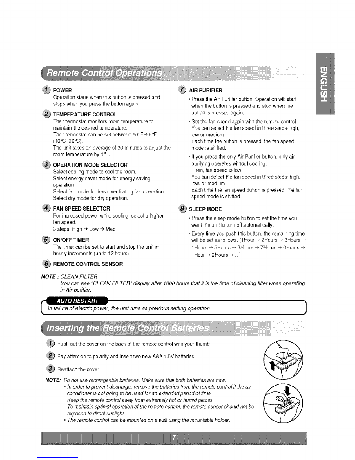
Push out the cover o_ the back o_the remote oantrol with your thumb
Pay a_ention to polarity and insed two new AAA 15V balteries
Rea'tNch tlhecover,
NOTE: Do _t use rechargeable batten'es Make sure that both batteries ate new.
•tr_order teprevent e, remove #_ebattenes from the re_.te o2ntrof if the air
cor_ff_oner )snot got_ to be us_ br an extorted period of time
Keep the remote control away from extremdy hot or humid places.
To maintain _tirr_l o_ra@n o_the remote cY_ntrol,the refute se_.r shou._d_t be
exposed :todtrect sun#ghL
•The refute contrM can ,bemount_ on a wall using the mountabb hMder. @

For maximum c_iing efficiency,,CLOSEthe vent, This wiil allow intemai air circuiation,
OPEN the vent to discharge stale air.
CLOSE-L VENT-LOPENi
_TE :_fore using t_ vendla#onfeature _sition the
vent leve_"straight _ _lling Part A out and
Part4 "" ........"'"
Aidlow ca_ be adiust_ by changing the direction of _e air conditioneCs louvers, This can also i_qcrease9_e
coo_i_gefficiency of _e air conditioner
•Adjusting Horizon_all Air Flow Direction
A_ust]ng the ve_cal _ouversleft and _ght w'il_
change horizontal airflow,,
•Adjusting Ve_ica| Air Flow Direction
Adiusting the horizontal vane up and do'_ will
change ve_ical airflow°The w_e ca_ _ adjuste_
by nudging _e back or up and dew# of the vane,
Adjusting hoHzonta! air f_ow Adjuring vertical air flow
• Recom_ndi_ orientation of |ouver's
Adjust louvers to face upwards when _oling to m_imize c_ling efficiency

Turn thepo,_t off and unpl_ th_powerplug _,to,te cleaning theair condtt_net,
The air filter behind the inlet grille should be checked and cleaned _ least once every,2 weeks (or as
necessa_) to maintain optimal performance of the air _ndiSoner.
How to remove the ,air filter
®
®
®
®
The grille may be opened from me top for easy
maiintenanceafter insta_l_ion,
Open the nlet grille by pulling off #}e exposed door
on the top of the unit (based on installation),
Pui!the tab siightiy to release the fi_ter,Pull the filter
iL_the same dire,ctionasthe ,openingi.
C:_eanthe fi_terw_lhwarm, soapy water, _e water
should be [below40'_ (104_)
Ri_se off and gently shake off excess water from the
filter. Let it dry bebre replaceing it
The base pan may ove#low due to Ihighhumidity. To drain _,e excess
water, remove _,e drain cap from the back ofthe unit a_,dsecure the
When pressing fl_edrainpipe into place, apply force in the dir_tion
away from f_e fins to avoid iniuring yourse#,

TheAirPurifyingfi_erbehind_.eairfiltershouldbech._kedandcleanedonceevery3monthsormoreoEenif
necessary.
AfterremovingtheAirPurifyingFilter0pull
slightlybrwardtoremovetheAirPurifyingfilter
SoaktheAirPurifyin,gFilterinwatermixedwitha
mild_tergentfor20_30minutes.
Dry'theAir Puri_ing Filter i# the shade for a
day(Re moisture must _ removed completely
on this paso)
Note the cuts of electric discharge lines.
Re-instal_the Air Purifying Fi_erto the odginal
Don't touch this Air Pud#yingFilter within
10 s_onds after opening the inlet griile;
it may cause an electric shock
The air _nditio_er emp!oys a proper drain me_od whereby the condensed water (moisture removed from _e
aiOis drained to _e outside,
Invery humid weather (;andfor reverse cycle mo_is in _e reverse mode} ,excessivecondensate water removed
from the air may cause some water to collect To remove this excess water you can instail the dram pan as
_taiied below
Take the drain pan which is located in the air
Remove the hole rubber from _e base-pa# (for
so_ mode_sl,.
Installthe drain pan to the right comer of the
cabinet with 4 (or 2} screws,
Conne_ the drain hose of 3/5'_insi_ diameter to
the outlet located at the bosom of the drain
pan,You can purchase,the drain hose or tubing
locally to sa_sfy your particuiar n_dso (Drain
hose is not supplied)
CABINET
PAN
DRAIN HOSE

z CAUTION
This appliance should be installed in ac_rdance wi_ national wiringregulations This guide acts as a
guide to help to explain product features.
®
®
®
You can choose be_n _o me_ods below according to your window stool shape and preference
*Fastenthe stopper using 2 screw holes°and lead
out the _wer cord through s_it"A'_,,
_,wer Cord
• Fasten tildestopper using left screw hole and rotate
properly to lead the power cord out_r,ough slit "B'
_wer

To prevent vibration and noise, make sure the unit
is inst_led securely and firmly,
!nstaHthe unit where the sunlight d_s not shine
direc_y on fne unit
There should be n_oolbstades0such as a fence and
wall, within 20" from the back dthe cabinet
b_caus,eit will prevent heat radiation of _e
condenser,
Restiction of outside air wili greatly reduce the
cooling efficiency of the air conditioner,
radiation
1/2"
Over 20"
Fence
CAUTION: Ai_s_e louvers of the ,cabinetmust remain expos_ toitheouts_e of the struc:ture_
Install the unit a li_le s_antedso the back is slightly !ower _an the front:(about i/2").
This will force condensed water to flow to _e outside,
Instail the unit w_hthe bottom a_ut 30"_60°'above the floor _evei,,
NOTE: AHsupporting parts shou_ _ _ured to fi_ wood, miaso,nry, Ofmetal.
• This unit is designed for installation in standard _uble
hung win®ws with a_ua_opening wi_hs _om 29"
to 41'"
•The top and bottom window sash must open sufficient!y
to allow a clear ve_ical opening of 18°'from _e bottom
of _,e upper sash tothe window stool
Y
29" to 41
18" rain.

_,= NAMF= OF PARqS Q'TY
i FRAME CURTAIN 2
£ SUPPORTBR,ACK£[ 2
3 S_LL BRACKET 2
4 LOOK NUT 4
SCR£W (TYPF A} 14
SCREW (TYPE B} 7
..... _CRE 5
5
6
7
8 _REW/TYP£ D) 2
9 CARRIAGE BOLT 2
10 FOAM s"rRiP .......................................1......
11 FOAM SEAL 1
12 WINDOW LOCKING BRACKET 1
13 UPPER GU!D8 ..........................! ......................
14 FOAM-PE 1
i5 FRAME GUIDE 2
iSCREWDRIV£R(% o), RULER_ KN|FE_ HAMMER_ PENC|L_ L£V£L ]
PREPARATION OF CHASSIS
Remove t}-_ _rews which fasten the cabinet at _th
sides ,andat the back,,
Sliide the unff from the cabinet by g_fi_ng the ba_ _n
ha_le and pulling foPward while bracing the canner.
Cut the window _sh seal to the proper I,ength.
Peel off tile _cNng and at_ch the Foam-Seal @to the
u_e_ide of the wi_,ow sash,
Remove t_ _c_ from fl_e,top u_er guide Foam-PE
_,and _ach itto _e bosom of the Upper Guide @.
Attac!! the u_r gui_ onto the top, of the _b,i_t with 3
Type A ._rews Q
In_rt the Frame Guides @ i_o the bottom of the
cabinet,
Inert the Frame Cudain d} into,the Upper Guide @ and
Frame Guid_ @,
Fasten the cut,ins to the unit:with 10 Type,
A _rews @.

_O_n thewindow.Marka_ineonthecenterof_e
windowstoolbelb,t_eenthesi_ windowstop
moldings.
Looselyattachthesillbrack_tothesuppo_
bracke_using_e carnage_:_itandtheI_k nut. C_ria_e
Attaclhthe si_lbracket to the window sill using _e
screws (Type B)..
Carefuliy place the cabinet on the window st_i
and a!ignthe center mark on _e bottom kont with
the center line maAed window stool..
Usingthe M-screw and the lock nut, a_ach the
suppo_ bracket to _e cabinet track ho_e.Usethe first
track hole after the sill bracket on the outer _g,e of
the window sill. Tighten #'_ecarria_ bo_ and the bck
nut. Be _ure the cabinet slants outward
C_inet
Track ho_e
si_
(Type B}
SillbracketQ
Fig. 2
CAUTION;' Do not drillia hole in the t:_ttom pan.
The unit is designed to operate with
approximateiy !/2" of water in bosom pan.. Windowst_l
Fig, 3
Pu_l_e bosom win®w sash down behind the Top
retainer bar u_il they meet
NOTE: i. Do not pull the windowsash down so tighty
that '_e movement of Framecu_ain is restricted..
Attach the cabinet to the window sloo_bydriving
the screws (Type B)through the cabinet into
window stooi.
2, _e cabinet should be installed with a vePtslight
tilt downward toward t_e outside..
Cabinet
Frame cudain

PuI_each Frame cu_ain fully to each window sash
track, and pu_l_e bosom window sash down behind
the Top ret_ner bar un#l it meets, track
A_ach each Frame cu_ain the window sash by using
screws (Type C,} (See Fig, 6)
Fro_ Angle
Q Screw(Ty_ B) Fig. 5,
Slide _e unit into the cabi#_et(See Fig, 7!
CAUTION: For s_uri#j pur_se, reinstall screws(Type A}
at cabinet's sides.
Power Cord Screw
Cut #_eFoam-strip to the proper len_h _d insert
between the,upper window sash and the bwier
windowsash,(S_ Fig, 8}
Fig. 7
Fig. 8
A_ach the Windowlocking bracket with a screw
,(TypeC,){See Fig, 9)
i
..,11 WindowIockin_
bracket
Fig. 9

:_ Attach the fromgrille to the cabinet by inse_ing the
t_s on '_e grille i_qtothe tabs o# the front of the
cabinet Push the grille in un_l it snaps into place
(See Fig,1O)
:1_ Lfff_e inlet grille and secure it with a screw (Type A}
through the front gdl_e,(SeeFig, 1O/
Window instaHa_onof room air _ndi_oner is now
completed See ELECTRICAL DATA for attaching
power cord to ei_rical out_et,
Fig. 10
Line Cord Plug Use WalllReceptacle PowerSupply
230V/208V
tandem type
Use 15 AMP' circuit.
Refer to, name#ate for
correct fusi_.
AJlwimng should be made in accordance with local electnca_codes and regu_atons
Aiuminum house widnglmay pose speciai problems,
Consult a qualified ele_rician

(PLEASE READ CAREFULL Y)
FOR'THE USER'S PERSONAL SAFETY, THIS
APPLIANCE MUST BE PROPERLY GROUNDED
The power cord of this appliance is equipped wi_ a
_ree-prong (grounding} plug Use this with a standard
_ree-slot (grounding} wa/power o_let (Fig 11) to
minimize the hazard of electric shock The customer
should have _e w_l receptacle and circuit checked by
a qualified ele_cian to make sure _e receptacle is
property grounded
230, 208, and 230/208 VOLT UNITS
These units are _uipp_ with a threeprong grounding
p_ugon the power supply cord, which must _ plugged
into a matching pro_Hy groun_d three-prong wall
receptacle for your protection against possible shock
hazard. If such an ou'tm is not present, one mu_ be
installed by a qualified electrician in ac_rdance with
the National Electrical Code and _ocalcodes and
ordinances
NOTE: DO NOT USE AN EXTENSION ,CORD
on 230,208, and 230/208 Voit units,
ty_ wall
teceplac_e
supply
c#rd existsbeforeuse
Fig. 11
NOT CUT OR REMOVE THE THIRD (GROUND)
PRONG _THE POWER PLUG.
FUSE = Use a time-delay fuse or circu_ breaker. Refer
_oserial plate br proper power supply

Before calling for service, p¢easereview the fo!lowir_ hstof common,problems and solution&
The air conditioner is operating no.ally when:
• Yo_Jhear a pinging noise, Thisiscaus_ by water being picked up by the condenser on rainy days or in highly
humid conditions This fea#Jreis designed to help remove moisture in '_e air and improve ,coolingefficiency,
•You hear the thermostat click This is caused bythe compressor cycle st_ing and stopping,
•iYousee water dr_ppingifrom the rear of_e unit W_er may _ _!lected in the base pan in highly humid
conditions or on rainy days Thiswater overflows and drips from the rear of the uni't
• You hear the fan running wh!e the compressor is silent. This is a _ormal operatJonaifeature.
The air conditioner may _ operating abnormally when:
The air conditioner
atal/
• Ma_e surethe plug is completely plugged into
• e outiet
• Check the fuse!cirou_ breaker box and replace
_e fuse or reset the breaker
, Inthe event of a power f_lure, set _e power
control to OFF°When the power is restored,
wait 3 minutes to restart the air _nditioner to
prevent the compressor from overloading
Air conditioner
does not,e,ooJ
Ice,appears on the
a# c_nditioner,
• Make surethere are no curtains, blinds
furn_ure or other ob_acles in fro_ of the air
conditioner
•Turn_e knob to a higher se_i_g The highest
se_ng provides maximum cooling
• Clean the fitter at least every 2 weeks. Refer to
_e 'Care and Maintenance' section (pg} ofthe
manual
• After _e air conditioner isturned on, you need
to give the air _ndihoner some time to coo_the
tO0 m
• Check for open furnace floor res{_ers and co{d
air returns.
• CLOSE _e air _nditioner vent
, See,Ice appears on the air conditioner below
• Ice may N_k the air flow and object the air
condi_oner from pro_dy cooling the room Set
_e fan at MED or HIGH _i/e se_in9 the
_e_ostat at I or 2 untl _e, ice meits_
_ You can refer to the Energy Star program in _taii at"_w energystar gov".
Table of contents
Other LG Air Conditioner manuals
Popular Air Conditioner manuals by other brands

Fujitsu
Fujitsu ASYG 09 LLCA installation manual

York
York HVHC 07-12DS Installation & owner's manual

Carrier
Carrier Fan Coil 42B Installation, operation and maintenance manual

intensity
intensity IDUFCI60KC-3 installation manual

Frigidaire
Frigidaire FAC064K7A2 Factory parts catalog

Sanyo
Sanyo KS2432 instruction manual

CLIMAVENETA
CLIMAVENETA a-CHD U-2T 606+2209 OPERATING AND INSTALLATION Manual

Midea
Midea EWK06CW5 user manual

Pioneer
Pioneer FAB Series installation manual

SPT
SPT WA-1511S user manual

Mitsubishi Electric
Mitsubishi Electric Mr.Slim MSZ-A24NA operating instructions

Mitsubishi Electric
Mitsubishi Electric PUHZ-RP50VHA4 Service manual