LG LA140CE User manual

LG
Room
Air Conditioner
SERVICE MANUAL
LG
CAUTION
website http://www.lgservice.com
• BEFORE SERVICING THE UNIT, READ THE SAFETY
PRECAUTIONS IN THIS MANUAL.
• ONLY FOR AUTHORIZED SERVICE PERSONNEL.
MODELS: LA140CE

2Room Air Conditioner
Air Conditioner Service Manual
TABLE OF CONTENTS
LG Model Name ...............................................................................................................................................3
Safety Precautions..........................................................................................................................................4
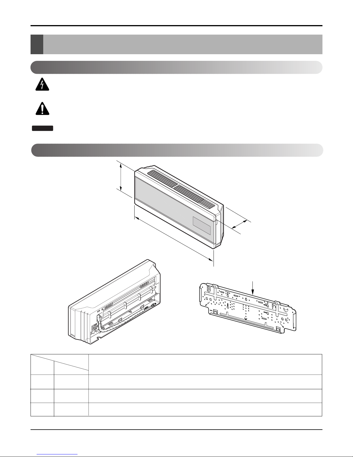
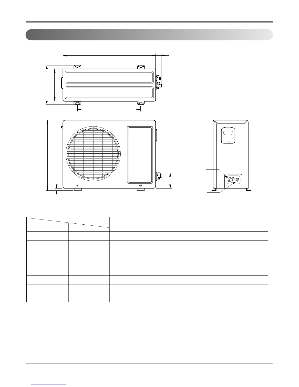
Dimensions .....................................................................................................................................................8
Symbols used in this Manual......................................................................................................................8
Indoor Unit..................................................................................................................................................9
Outdoor Unit...............................................................................................................................................9
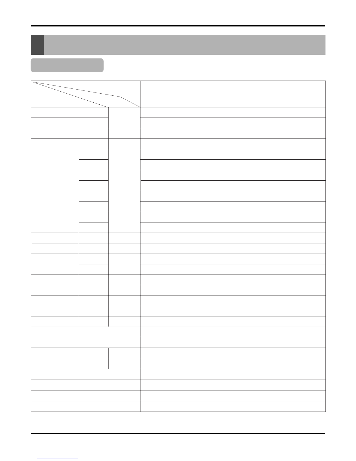
Product Specifications ................................................................................................................................10
Installation .....................................................................................................................................................11
Select the Best Location .........................................................................................................................11
Piping Length and Elevation.....................................................................................................................11
Fixing Installation Plate ............................................................................................................................12
Drill a Hole in the wall...............................................................................................................................12
Flaring Work.............................................................................................................................................13
Connecting the Piping ..............................................................................................................................14
Connecting the Cables.............................................................................................................................19
Connection method of the connecting cable(Example)............................................................................20
Connect the cable to the indoor unit.........................................................................................................21
Checking the Drainage.............................................................................................................................22
Forming the Piping ...................................................................................................................................23
Air Purging ...............................................................................................................................................24
Test Running ............................................................................................................................................26
Operation ......................................................................................................................................................28
Function of Controls .................................................................................................................................28
Display Function.......................................................................................................................................34
Self-diagnosis Function............................................................................................................................34
Remote Control Operations......................................................................................................................35
Disassembly ..................................................................................................................................................36
Indoor Unit................................................................................................................................................36
Schematic Diagram.......................................................................................................................................39
Electric control Device..............................................................................................................................39
Wiring Diagram.........................................................................................................................................41
Components Location ..............................................................................................................................42
Troubleshooting Guide .................................................................................................................................46
Refrigeration Cycle Diagram ....................................................................................................................46
2-way, 3-way Valve ...................................................................................................................................47
Cycle Parts...............................................................................................................................................52
Electronic Parts ........................................................................................................................................53
Exploded View & Replacement Parts List .................................................................................................62
Indoor Unit...............................................................................................................................................63
Outdoor Unit............................................................................................................................................64

Service Manual 3
LG Model Name
12 - 345678910
Code Type Code of Model Meaning
1 Producing Center, A~Z L: Chang-won R22 N: India
Refrigerant A: Chang-won R410A Z: Brazil
C: Chang-won R407C D: Indonesia
T: China M: Mexico
K: Turkey R22 V: Vietnam
E: Turkey R410A S: Out Sourcing
H: Thailand
2 Product Type A~Z S: Split Type Air Conditioner
3 Cooling/Heating/Inverter A~Z C: Cooling only
H: Heat pump
X: C/O + E/Heater
Z: H/P + E/Heater
V: AC Inverter C/O
N: AC Inverter H/P
Q: DC Inverter C/O
W: DC Inverter H/P
4, 5 Capacity 0~9 Cooling/Heating Capacity
Ex. "09" →9,000 Btu/h
6 Electric Range 1~9 1: 115V/60Hz, A: 220V, 50Hz, 3Phase
A~Z 2: 220V/60Hz B: 208~230V, 60Hz, 3Phase
3: 208-230V/60Hz C: 575V, 50Hz, 3Phase
5: 200-220V/50Hz D: 440~460, 60Hz, 3Phase
6: 220-240V/50Hz E: 265V, 60Hz
7: 110V, 50/60Hz F: 200V, 50/60Hz
8: 380-415V/50Hz
9: 380-415V/60Hz
7 Chassis A~Z Name of Chassis of Unit
Ex. LSP →SP Chassis
8 Look A~Z Look,
Color (Artcool Model)
9 Function A~Z
10 Serial No. 1~9 LG Model De
* ARTCOOL COLOR
velopment Serial No.
Basic A
Basic+4Way B
Plasma Filter C
Plasma Filter+4 Way D
Tele+LCD E
Tele+LCD+Nano plasma+4Way F
Nano Plasma F+(A/changeove)+A/clean+Low A G
Nano Plasma F+(A/changeove)+A/clean+4way+Low A H
Tele+LED+4way I
Internet J
Plasma F+4Way+Oxy generator K
Nano Plasma F+(A/changeove)+A/clean L
Nano Plasma F+(A/changeove)+A/clean+4way M
Nano Plasma F+(A/changeove)+A/clean+PTC N
Nano Plasma F+(A/changeove)+Autoclean+4way+PTC P
Nano Plasma F+(A/changeove)+A/clean+4way+Low A+PTC Q
Negative ION+A/Clean R
(Nano)Plasma+Negative ION+A/Clean S
4way+(Nano)Plasma F+Negative ION+Healthy dehumidification+A/Clean
T
Nano Plasma F+4Way+(A/changeove)+A/clean+ U
R Mirror
W White
B Blue
D Wood
M Metal
C Cherry
2003

4Room Air Conditioner
Safety Precautions
To prevent injury to the user or other people and property damage, the following instructions must
be followed.
■Incorrect operation due to ignoring instruction will cause harm or damage. The seriousness is
classified by the following indications.
■Meanings of symbols used in this manual are as shown below.
This symbol indicates the possibility of death or serious injury.
This symbol indicates the possibility of injury or damage to properties only.
Be sure not to do.
Be sure to follow the instruction.
■Installation
Always perform grounding.
• Otherwise, it may cause electrical shock.
Don’t use a power cord, a plug or a loose socket
which is damaged.
• Otherwise, it may cause a fire or electrical shock.
For installation of the product, always contact the
service center or a professional installation agency.
• Otherwise, it may cause a fire, electrical shock,
explosion or injury.
Securely attach the electrical part cover to the
indoor unit and the service panel to the outdoor
unit.
• If the electrical part cover of the indoor unit and the
service panel of the outdoor unit are not attached
securely, it could result in a fire or electric shock due to
dust, water, etc.

Service Manual 5
Safety Precautions
Always install an air leakage
breaker and a dedicated switch-
ing board.
• No installation may cause a fire and
electrical shock.
Do not keep or use flammable
gases or combustibles near the
air conditioner.
• Otherwise, it may cause a fire or
the failure of product.
Ensure that an installation frame
of the outdoor unit is not dam-
aged due to use for a long time.
• It may cause injury or an accident.
Do not disassemble or repair the
product randomly.
• It will cause a fire or electrical
shock.
Do not install the product at a
place that ther is concern of
falling down.
• Otherwise, it may result in personal
injury.
Use caution when unpacking and
installing.
• Sharp edges may cause injury.
Do not share the outlet with
other appliances.
• It will cause an electric shock or a
fire due to heat generation.
Do not use the damaged power
cord.
• Otherwise, it may cause a fire or
electrical shock.
Do not modify or extend the
power cord randomly.
• Otherwise, it may cause a fire or
electrical shock.
Take care so that the power cord
may not be pulled during opera-
tion.
• Otherwise, it may cause a fire or
electrical shock.
Unplug the unit if strange
sounds, smell, or smoke comes
from it.
• Otherwise, it may cause electrical
shock or a fire.
Keep the flames away.
• Otherwise, it may cause a fire.
■Operation
Wax
Thinner

6Room Air Conditioner
Safety Precautions
Take the power plug out if neces-
sary, holding the head of the
plug and do not touch it with wet
hands.
• Otherwise, it may cause a fire or
electrical shock.
Do not use the power cord near
the heating tools.
• Otherwise, it may cause a fire and
electrical shock.
Do not open the suction inlet of
the indoor/outdoor unit during
operation.
• Otherwise, it may electrical shock
and failure.
Do not allow water to run into
electrical parts.
• Otherwise, it may cause the failure
of machine or electrical shock.
Hold the plug by the head when
taking it out.
• It may cause electric shock and
damage.
Never touch the metal parts of
the unit when removing the filter.
• They are sharp and may cause
injury.
Do not step on the indoor/outdoor unit and do not
put anything on it.
• It may cause an injury through dropping of the unit or
falling down.
Do not place a heavy object on the power cord.
• Otherwise, it may cause a fire or electrical shock.
When the product is submerged into water, always
contact the service center.
• Otherwise, it may cause a fire or electrical shock.
Take care so that children may not step on the out-
door unit.
• Otherwise, children may be seriously injured due to
falling down.

Service Manual 7
Safety Precautions
Wax
Thinner
■Installation
Install the drain hose to ensure that drain can be
securely done.
• Otherwise, it may cause water leakage.
Install the product so that the noise or hot wind
from the outdoor unit may not cause any damage
to the neighbors.
• Otherwise, it may cause dispute with the neighbors.
Always inspect gas leakage after the installation
and repair of product.
• Otherwise, it may cause the failure of product.
Keep level parallel in installing the product.
• Otherwise, it may cause vibration or water leakage.
Avoid excessive cooling and perform ventilation
sometimes.
• Otherwise, it may do harm to your health.
Use a soft cloth to clean. Do not use wax, thinner,
or a strong detergent.
• The appearance of the air conditioner may deteriorate,
change color, or develop surface flaws.
Do not use an appliance for special purposes such
as preserving animals vegetables, precision
machine, or art articles.
• Otherwise, it may damage your properties.
Do not place obstacles around the flow inlet or out-
let.
• Otherwise, it may cause the failure of appliance or an
accident.
■Operation

8Room Air Conditioner
Dimensions
Dimensions
Installation plate
D
H
W
Indoor Unit
This symbol alerts you to the risk of electric shock.
This symbol alerts you to hazards that may cause harm to the
air conditioner.
This symbol indicates special notes.
NOTICE
Symbols used in this Manual
MODEL
DIM Unit
W mm 1030
H mm 290
D mm 153
14K Btu Series

Service Manual 9
WL2
L3
L1
D
H
L4
L5
Gas side
(3-way valve)
Liquid side
(2-way valve)
MODEL 14K Btu Series
DIM unit
W mm 770
H mm 540
D mm 245
L1 mm 285
L2 mm 64
L3 mm 518
L4 mm 10
L5 mm 100
Dimensions
Outdoor Unit

10 Room Air Conditioner
Product Specifications
Table-1
Model Name
Item Unit
Cooling Capacity Btu/h
Heating Capacity
Moisture Removal l/h
Power Source Ø, V, Hz
Cooling W
Heating
Running Cooling A
Current Heating
E.E.R. Cooling Btu/hW
C.O.P Heating
Refrigerant g
Airflow Direction Control (Up & Down)
Remocon Type
inch(mm)
Sleeping Operation
Drain Hose
Connecting Cable(p*mm2)
Power Cord(p*mm2)
Air Circulation
Noise Level
Input
m3/min
dB (A)±3
Indoor
Outdoor
Indoor
Outdoor
Indoor
Outdoor
Indoor
Outdoor
Indoor
Outdoor
Liquid
Gas
Service Valve
Motor Output
Dimensions
(W x H x D)
Net. Weight
W
mm
kg
LA140CE
14000
-
1.5
1Ø, 115V, 60Hz
9
26
41
48
1400
-
13
-
10.0
-
24
27
1030 x 290 x 153
770 x 540 x 245
9.5
35
900(R22)
O
L.C.D Wireless
1/4(6.35)
1/2(12.7)
O
O
18: 4*0.75
14: 3*2.5

Service Manual 11
Installation
Installation
Indoor unit
1. Do not have any heat or steam near the unit.
2. Select a place where there are no obstacles in front of the unit.
3. Make sure that condensation drainage can be conveniently rout-
ed away.
4. Do not install near a doorway.
5. Ensure that the interval between a wall and the left (or right) of
the unit is more than 5cm(1.96"). The unit should be installed as
high as possible on the wall, allowing a minimum of 10cm(3.9")
from ceiling.
6. Use a stud finder to locate studs to prevent unnecessary dam-
age to the wall.
Outdoor unit
1. If an awning is built over the unit to prevent direct sunlight or
rain exposure, make sure that heat radiation from the con-
denser is not restricted.
2. Ensure that the space around the back and sides is more
than 10cm(3.9"). The front of the unit should have more than
70cm(28") of space.
3. Do not place animals and plants in the path of the warm air.
4. Take the weight of the air conditioner into account and select
a place where noise and vibration are minimum.
5. Select a place where the warm air and noise from the air
conditioner do not disturb neighbors.
Select the best Location
More than 10cm(3.9")
More than
5cm(1.96")
More than
2.3m(7.5ft)
More than
5cm(1.96")
CAUTION: Install the indoor unit on the wall where the height from the floor is
more than 2 meters (6.6ft).
More than
10cm(3.9")
More than
10cm(3.9")
More than
60cm(24")
More than 60cm(24")
More than
70cm(28")
Piping Length and Elevation
14K 1/2" 1/4" 7.5(24.6ft) 7(23ft) 15(50ft) 20
Pipe Size
Capacity
(Btu/h)
GAS LIQUID
Max.
Length A (m)
Additional
Refrigerant (g/m)
Max.
Elevation B (m)
Standard
Length (m)
Outdoor unit
Indoor unit
A
B
Outdoor unit
Indoor unit
A
B
A
Oil trap
Outdoor unit
Indoor unit
B
If piping length is more than 5m
CAUTION: Capacity is based
on standard length and maxi-
mum allowance length is on
the basis of reliability.
Oil trap should be installed
every 5~7 meters(16.4~23ft).

12 Room Air Conditioner
Installation
The wall you select should be strong and solid
enough to prevent vibration
1. Mount the installation plate on the wall with
type "A" screws. If mounting the unit on a concrete
wall, use anchor bolts.
•Mount the installation plate horizontally by aligning
the centerline using a level.
2. Measure the wall and mark the centerline. It is also
important to use caution concerning the location of
the installation plate-routing of the wiring to power
outlets is through the walls typically. Drilling the
hole through the wall for piping connections must
be done safely.
Fixing Installation Plate
Installation Plate
Type "A" screw
Installation plate
Ø70mm(2.76")
Left rear piping Right rear piping
C
D
B
AØ70mm(2.76")
(SU)
•Drill the piping hole with a ø70mm(2.76") hole core
drill. Drill the piping hole at either the right or the left
with the hole slightly slanted to the outdoor side.
Drill a Hole in the Wall
5-7mm
(3/16"~5/16")
Indoor
WALL
Outdoor
ABCD
SU 92 44 67 44
(11k~14k)
CHASSIS
(Grade)
Distance (mm)

Service Manual 13
Installation
Flaring Work
Cutting the pipes and the cable.
1. Use the piping kit accessory or the pipes purchased
locally.
2. Measure the distance between the indoor and the out-
door unit.
3. Cut the pipes a little longer than measured distance.
4. Cut the cable 1.5m longer than the pipe length.
Removing burrs
1. Completely remove all burrs from the cut cross section of
pipe/tube.
2. Put the end of the copper tube/pipe in a downward direc-
tion as you remove burrs in order to avoid dropping burrs
into the tubing.
Putting nut on
•Remove flare nuts attached to indoor and outdoor unit,
then put them on pipe/tube having completed burr
removal.
(not possible to put them on after flaring work)
Flaring work
1. Firmly hold copper pipe in a die in the dimension shown
in the table below.
2. Carry out flaring work with the flaring tool.
Copper
pipe
90°Slanted Uneven Rough
Pipe
Reamer
Point down
Flare nut
Copper tube
mm inch mm
Ø6.35 1/4 0~0.5
Ø9.52 3/8 0~0.5
Ø12.7 1/2 0~0.5
Ø15.88 5/8 0~1.0
Ø19.05 3/4 1.0~1.3
Outside diameter A
Bar
Copper pipe
Clamp handle Red arrow mark
Cone
Yoke
Handle
Bar
"A"
Main cause for gas leakage is due to defect in flaring work. Carry out correct flaring work in the following procedure.

14 Room Air Conditioner
Installation
Check
1. Compare the flared work with the figure by.
2. If a flared section is defective, cut it off and do flaring
work again.
Inclined
Inside is shiny without scratches
Smooth all round
Even length
all round
Surface
damaged
Cracked Uneven
thickness
= Improper flaring =
Indoor
1. Prepare the indoor unit's piping and drain hose for installation through the wall.
2. Remove the plastic tubing retainer(see the illustration
by) and pull the tubing and drain hose away from
chassis.
3. Replace the plastic tubing holder in the original posi-
tion.(Optional)
1. Route the indoor tubing and the drain hose in the
direction of rear right.
2.
Insert the connecting cable into the indoor unit from the
outdoor unit through the piping hole.
•Do not connect the cable to the indoor unit.
•Make a small loop with the cable for easy connec-
tion later.
3. Tape the tubing, drain hose, and the connecting
cable. Be sure that the drain hose is located at the
lowest side of the bundle. Locating at the uper side
can cause drain pan to overflow inside the unit.
CAUTION: If the drain hose is routed inside
the room, insulate the hose with an insulation
material* so that dripping from
"sweating"(condensation) will not damage fur-
niture or floors.
*Foamed polyethylene or equivalent is recom-
mended.
Connecting the Piping
For right rear piping
Drain hose
Connecting
pipe
Connecting cable
Tape
Drain hose

Service Manual 15
Installation
4. Indoor unit installation
Hook the indoor unit onto the upper portion of the
installation plate.(Engage the two hooks of the rear
top of the indoor unit with the upper edge of the
installation plate.) Ensure that the hooks are properly
seated on the installation plate by moving it left and
right.
Press the lower left and right sides of the unit against
the installation plate until the hooks engage into their
slots(clicking sound).
Connecting the piping to the indoor unit and drain
hose to drain pipe.
1. Align the center of the pipes and sufficiently tighten
the flare nut by hand.
2. Tighten the flare nut with a wrench.
3. When extending the drain hose at the indoor unit,
install the drain pipe.
Wrap the insulation material around the connecting
portion.
1. Overlap the connection pipe insulation material and
the indoor unit pipe insulation material. Bind them
together with vinyl tape so that there may be no gap.
2. Wrap the area which accommodates the rear piping
housing section with vinyl tape.
3. Bundle the piping and drain hose together by wrap-
ping them with vinyl tape for enough to cover where
they fit into the rear piping housing section.
Drain hose
Connecting
cable
Indoor unit tubing Flare nut Pipes
Wrench
Indoor unit tubing
Open-end wrench (fixed)
Connection pipe
Flare nut
mm inch kg.m
Ø6.35 1/4 1.8
Ø9.52 3/8 4.2
Ø12.7 1/2 5.5
Outside diameter Torque
Vinyl tape(narrow)
Adhesive
Drain pipe
Indoor unit drain hose
Plastic bands Insulation material
Vinyl tape(narrow)
Connection pipe
Connecting cable
Vinyl tape (wide) Wrap with vinyl tape
Indoor unit pipe
Pipe
Wrap with vinyl tape
Drain hose
Pipe
Vinyl tape(wide)

16 Room Air Conditioner
Installation
1. Route the indoor tubing and the drain hose to the
required piping hole position.
2. Insert the piping, drain hose, and the connecting
cable into the piping hole.
3.
Insert the connecting cable into the indoor unit.
•Don't connect the cable to the indoor unit.
•Make a small loop with the cable for easy connec-
tion later.
4. Tape the drain hose and the connecting cables.
5. Indoor unit installation
•Hang the indoor unit from the hooks at the top of the
installation plate.
•Insert the spacer etc. between the indoor unit and
the installation plate and separate the bottom of the
indoor unit from the wall.
Connecting the piping to the indoor unit and the
drain hose to drain pipe.
1. Align the center of the pipes and sufficiently tighten
the flare nut by hand.
2. Tighten the flare nut with a wrench.
3. When extending the drain hose at the indoor unit,
install the drain pipe.
For left rear piping
Drain pipe
Connecting
cable
1 2
Installation plate
Spacer
Indoor unit
8cm
Indoor unit tubing Flare nut Pipes
Wrench
Indoor unit tubing
Connection pipe
Flare nut
Open-end wrench (fixed)
mm inch kg.m
Ø6.35 1/4 1.8
Ø9.52 3/8 4.2
Ø12.7 1/2 5.5
Outside diameter Torque
Vinyl tape
Adhesive
Drain hose
Indoor unit drain hose
(narrow)

Service Manual 17
Installation
Wrap the insulation material around the connecting
portion.
1. Overlap the connection pipe heat insulation and the
indoor unit pipe heat insulation material. Bind them
together with vinyl tape so that there may be no gap.
2. Wrap the area which accommodates the rear piping
housing section with vinyl tape.
3. Bundle the piping and drain hose together by wrap-
ping them with cloth tape over the range within which
they fit into the rear piping housing section.
Reroute the pipings and the drain hose across the
back of the chassis.
Set the pipings and the drain hose to the back of
the chassis with the tubing holder.
•Hook the edge of tubing holder to tap on chassis and
push the bottom of tubing holder to be engaged at the
bottom of chassis.
Indoor unit installation
1. Remove the spacer.
2. Ensure that the hooks are properly seated on the
installation plate by moving it left and right.
3. Press the lower left and right sides of the unit against
the installation plate until the hooks engage into their
slots(clicking sound).
Plastic bands Insulation material
Vinyl tape(narrow)
Connection
pipe
Connecting cable
Indoor
unit piping
Pipe
Vinyl tape
(wide) Wrap with vinyl tape
Drain hose
Vinyl tape(narrow)
Pipe
Wrap with
vinyl tape(wide)
Piping for
passage through
piping hole
Drain hose
Connecting
cable
Tubing holder

18 Room Air Conditioner
Installation
CAUTION: Installation Information
For left piping. Follow the instruction below.
Good case
•Press on the upper side of clamp and unfold the tub-
ing to downward slowly.
Bad case
•Following bending type from right to left may cause
damage to the tubing.
Outdoor
Align the center of the pipings and sufficiently tighten
the flare nut by hand.
Finally, tighten the flare nut with torque wrench until the
wrench clicks.
•When tightening the flare nut with torque wrench,
ensure the direction for tightening follows the arrow on
the wrench.
mm inch kg.m
Ø6.35 1/4 1.8
Ø9.52 3/8 4.2
Ø12.7 1/2 5.5
Ø15.88 5/8 6.6
Ø19.05 3/4 6.6
Outside diameter Torque
Outdoor unit
Liquid side piping
(Smaller diameter)
Gas side
piping
(Bigger
diameter)
Torque wrench

Service Manual 19
Installation
Connecting the Cables
1. Remove the cover control from the unit by loosening
the 3 screws.
2. Dismount caps on the conduit panel.
3. Temporarily mount the conduit tubes on the conduit
panel.
4. Properly connect both the power supply and low volt-
age lines to the corresponding terminals on the termi-
nal block.
5. Ground the unit in accordance with local codes.
6. Be sure to size each wire allowing several inches
longer than the required length for wiring.
7. Use lock nuts to secure the conduit tubes.
Connector trade size for this unit is 1/2".
Refer to "How to connect wiring to the terminals" for
instructions on connecting depending on the wire type
you are using.
WARNING:
•Be sure to comply with local codes while
running the wire from the indoor unit to
the outdoor unit(size of wire and wiring
method, etc).
•Every wire must be connected firmly.
•No wire should be allowed to touch
refrigerant tubing, the compressor or any
moving parts.
Power Supply
NOTICE
1
Indoor Unit Outdoor Unit
2
3
4
1
2
3
4
5
6
GTo
branch
circuit
Ground
Power supply a
L1*
L2
Connecting cable(Low voltage) b
Terminal
(4P)
Terminal
(6P)
Wiring Diagram
*L1 is neutral for 115V models.
Outdoor unit
Terminal block
Over 5mm
(2")
Cover control
Conduit panel
Connecting
cable
Power supply
cord
1. shows field wiring.
2. Separately wire the high and low voltage line.
3. Use heat-proof electrical wiring capable of withstand-
ing temperatures up to 167°F.
4. Use outdoor and waterproof connection cable rated
more than 300V for the connection between indoor
and outdoor unit.
(For example, Type SJO-WA)
NOTICE
Model
14K 1Ø, 115V 14 18 20A
Power
source
Fuse or breaker
Capacity
AWG(MIN)

20 Room Air Conditioner
Installation
Connection method of the connecting cable(Example)
1. Dismount two-caps on the conduit panel.
2. Make a hole appropriate for the passage of connection cable
through on cap by tool. (for low voltage line)
3. Pass the connecting cable through the hole.
4. Properly connect the cable on the terminal block.
5. Fix the connection cable with clamp cord provided on the
unit not to have strain at the terminal when the connection
cable is pulled outside up to a 35 pound weight.
6. Wind the vinyl tape round the connecting cable for sealing
between the surface of the connection cable and cap.
7. Mount the taped part of cable on the cap.
8. Finally, mount the holed cap with the
wound cable on the conduit panel.
WARNING:
Loose wiring may cause the terminal to over-
heat or result in unit malfunction. A fire hazard
may also exist. Therefore, be sure all wiring is
tightly connected.
When connecting each power wire to the corre-
sponding terminal, follow instructions "How to con-
nect wiring to the terminals" and fasten the wire
tightly with the fixing screw of the terminal plate.
How to connect wiring to the terminals
•For solid core wiring (or F-cable)
1. Cut the wire end with a wire cutter of wire-cut-
ting pliers, then strip the insulation to expose
the solid wire about 25mm(15/16")
2. Using a screwdriver, remove the terminal
screw(s) on the terminal plate.
3. Using pliers, bend the solid wire to from a loop
suitable for the terminal screw.
4. Shape the loop wire properly, place it on the ter-
minal plater and tighten securely with the termi-
nal screw using a screwdriver.
•For strand wiring
1. Cut the wire end with a wire cutter or wire-cut-
ting pliers, then strip the insulation to expose
the strand wiring about 10mm(3/8").
2. Using a screwdriver, remove the terminal
screw(s) on the terminal plate.
3. Using a round terminal fastener or pliers,
securely clamp each stripped wire end with a
round terminal.
4. Position the round terminal wire, and replace
and tighten the terminal screw using a screw-
driver.
G
Terminal
block
Cap
(Remove)
Clamp cord
Lock nut
Conduit panel
Cap(Reuse)
Taping
(for sealing)
Low voltage line
(connecting cable)
Power supply line
(1ø, 115V, 208/230V)
Hole
(for low
voltage line)
Loop
Round
terminal
Insulation
Strip 25mm(15/16")
Strip 10mm(3/8")
Solid wire
Strand wire
Screw with
special washer
Screw with
special washer
Round terminal
Terminal plate
Wire
Wire
Round terminal
Other manuals for LA140CE
1
Table of contents
Other LG Air Conditioner manuals
Popular Air Conditioner manuals by other brands

Panasonic
Panasonic PZ2 Series operating instructions

Hisense
Hisense AUC-18UX4SGAA Instruction and installation manual

Sanyo
Sanyo CH0971 Technical & service manual

AirStage
AirStage ASUA7RLAV installation manual

Technibel
Technibel KPAFP125R5IA Series instruction manual

nedis
nedis ACMB1WT9 quick start guide