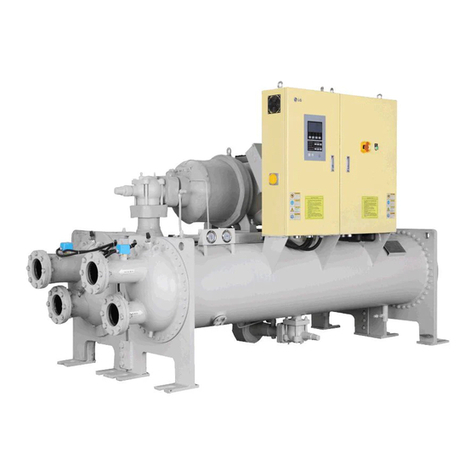
LG RCWFH Series User manual

www.lge.com
INSTRUCTION MANUAL
Water-Cooled Turbo Chiller
Please read the safety precautions before use.
This content is to ensure the safety of users and to prevent property damages.
Keep the instruction manual in a place that is accessible to other users.
Only authorized people can use the product.
Model : RCWFH Series (200-3000RT)
(For AC Smart Premium Control System)
ENGLISH
P/NO : MFL68929306 (Rev 0)

ENGLISH
2
For your records
Staple your receipt to this page in case you need it to prove the date of purchase or for warranty
purposes. Write the model number and the serial number here:
Model number :
Serial number :
You can find them on a label on the side of each unit.
Dealer’s name :
Date of purchase :

ENGLISH
3
1. CAUTIONS FOR SAFETY _ WARNING/CAUTION
It can be dangerous when moving, installing and placing the system for its high pressure, electric
devices and heavy weight especially when lifting the unit in a limited space(rooftop, lifted struc-
ture, etc.).
Please read carefully the warnings and cautions on this manual and the labels attached on the
unit, and follow the instructions.
Please follow the following instructions to prevent any injury or property damage
• It may result in an injury or damages when neglecting the instructions on in this manual.
The seriousness of the result can be classified as the following signs.
• Please note that any failure of system resulted by user’s careless maintenance, natural disaster
or the failure of the power cable shall not be warranted regardless of the warranty period.
• Please note that any part of this manual can be revised without notice for the product improve-
ment.
WARNING
It can result in serious injury or death when the directions are ignored.
CAUTION
It can result in minor injury or product damage when the directions are ignored.
The meanings of the symbols used in this manual are as follows.
This is the symbol to call attention for the issues and operations that may cause danger.
To prevent the occurrence of the danger, read carefully and follow the instructions.
This is the symbol showing the how-to-use instruction in order to prevent danger.
Follow the direction.
1-1. WARNING
• Have all electric work done by a licensed electrician according to "Electric Facility Engineering Standard" and "Interior
Wire Regulations" and the instructions given in this manual and always use a special circuit.
- If the power source capacity is inadequate or electric work is performed improperly, electric shock or fire may re-
sult.
• Ask the dealer or an authorized technician to install the chiller unit.
- Improper installation by the user may result in water leakage, electric shock, or fire.
• For re-installation of the installed product, always contact a dealer or an Authorized Service Center.
- There is risk of fire, electric shock, explosion, or injury.
• Make sure to equip the circuit breaker and fuse.
- Improper wiring or installation may cause fire or electric shock.
• Do not disassemble, repair or reconfigure the unit.
- LG Electronics is not responsible for the any damage or loss from the arbitrary disassembly, repair or reconfigura-
tion of the unit.
• Make sure to ground the unit properly.
- There is risk of fire or electric shock.
• Do not store or use flammable gas or combustibles near the chiller unit
- There is risk of fire or failure of product.
• Do not reconstruct to change the settings of the protection devices.
- If the pressure switch, thermal switch, or other protection device is shorted and operated forcibly, or parts other
than those specified by LGE are used, fire or explosion may result.
• Install the unit on a foundation where the heavy weight can be supported.
- Insufficient strength of the foundation to support the chiller operation may cause the unit failure or injury.
!
!
!

ENGLISH
4
• Installing the product in small space requires separate measures to keep the leakage of the refrigerant within the
safety limits in case of any leakage.
- Consult the authorized dealer for appropriate measures to prevent the refrigerant leakage from exceeding the
safety limits. The leakage of refrigerant exceeding the safety limit may result in dangerous situations due to the
lack of oxygen level in the room.
• Securely install the cover of control box and the panel.
- If the cover and panel are not installed securely, dust or water may enter the unit and fire or electric shock may re-
sult.
• Do not operate the unit arbitrarily.
- Incorrect operation of the unit may cause dangerous situations such as unit defects, leakage or electric shock. Al-
ways consult the authorized dealer.
• Do not use damaged circuit breaker or fuse works correctly all the time.
- It may cause fire, electric shock or injury.
• Keep the control panel from any water getting in.
- Do not wash the control panel with water. It can cause electric shock or defects.
• When the product is soaked (flooded or submerged), contact an Authorized Service Center.
- There is risk of fire or electric shock.
• Use a dedicated outlet for this unit.
- There is risk of fire or electric shock.
• Make sure to charge only the exclusive refrigerant R134a when installing or moving to other place.
- If a different refrigerant or air is mixed with the original refrigerant, the refrigerant cycle may malfunction and the
unit may be damaged.
• Do not touch the power switch with wet hands.
- There is risk of fire, electric shock, explosion, or injury.
• Ventilate before operating the chiller unit when gas leaked out.
- Do not use a phone or operate the power switch at this time. It may cause fire or explosion.
• Do not put any heavy object on the top of the unit or climb on the unit.
- It may cause defects or injury.
• Be careful with the rotating part.
- Do not put your fingers or a stick to the rotating part. It can cause injury.
• Use the fuse and circuit breaker with rated capacity.
- It may cause fire and defects.
• Redesigning the control box is prohibited.
- Lock the control box with possible locking device and if you need to open the control box inevitably, turn off the
main power first.
• Do not touch the wiring or a parts inside the panel.
- It may cause electric shock, fire or defects.
• Follow the permitted pressure level
- Follow the regulated pressure for cold water, cooling water, refrigerant etc.
• Do not change the set values.
- Do not change the set values of the controller and safety devices. Operating with inappropriate setting can cause
damages. When changing the setting values, please consult with the specialist.
• Be careful of fire, earthquake and lightening.
- In case of any natural disaster such as fire, earthquake or lightening, immediately stop operating the unit. If you
continue to operate the unit, it can cause a fire or electronic shock.
• Follow all safety code.
- When operate the chiller, follow the precautions on the manual, tag, sticker and label.
• Use of undesignated refrigerant and oil is prohibited.
- Do not use undesignated refrigerant, freezer oil and brine. It may cause serious effect to the compressor and
parts defect.
• During the installation and service, shut down the power supply.
- Electric shock can cause injury and death. Mark and check all switches so that the power is not recovered until
the work is completed.

ENGLISH
5
• Wear safety equipment
- Wear safety glasses and work gloves. Be careful when installing or operating the chiller and operating the electri-
cal components.
• Always run fluid through heat exchangers when adding or removing refrigerant charge.
- Potential damage of the tube within the heat exchanger can be prevented. Use Appropriate brine solution in
cooler fluid loops to prevent the freezing of heat exchangers when equipment is exposed to temperature below
0°C.
• Do not vent refrigerant relief valves within a building.
- Outlet from relief valves must be vented outdoors in accordance with the latest edition of ANSI/ASHRAE(Ameri-
can National Standards Institute/American Society of Heating, Refrigeration and Air Conditioning Engineers) 15
(Safety Code for Mechanical Refrigeration). The accumulation of refrigerant in an enclosed space can displace
oxygen and cause asphyxiation. Provide adequate ventilation in enclosed or low overhead areas. Inhalation of high
concentrations of refrigerant gas is harmful and may cause heart irregularities, unconsciousness or death. Misuse
can be critical. Refrigerant gas is heavier than air and reduces the level of oxygen. It can cause irritation to eyes
and skin.
• Be careful of water leakage.
- In case of any water leakage in the pump or pipe, immediately stop operating the unit. It may cause electric
shock, electricity leakage or defects. Be careful of electric shock.
• Always ground the chiller during installation.
- It may cause electric shock.
• Do not leave refrigerant system open to air any longer than necessary.
- If the repair cannot be completed, seal the circuits to prevent any contamination or rust within the product, and
charge dry nitrogen.
• Do not reuse compressor oil.
- It can damage the product.
• During installation, make the specified grounding before supplying the power, and during the dismantling, remove
the grounding line at the end of the task.
• Use appropriate meters for measurement. Otherwise, it may cause injury or electric shock.
• Check all power connected to the control panel or starter panel to be shut off while applying the power.
- It may cause electric shock.
• Make sure to discharge the electric current before inspection or repair work.
- It may cause injury or electric shock.
• Do not open the 2nd phase side of the current transformer when power is on.
- High voltage could be discharged causing an electric shock.
• Remove foreign objects(working tools, wires, bolts, washers) after installation, inspection, and repair work.
- They may cause injury, fire, or damage.
• When using a condenser, make sure to verify the complete discharge before applying the power again. (Re-power-
ing within 5 min. is prohibited.)
- It may cause electric shock, fire, damage, or malfunction.
• Change the condenser in case that the expansion exceeds the recommended limit.
- It may cause electric shock, fire, damage, or malfunction.

ENGLISH
6
1-2. CAUTION
Operation & Maintenance
• Always check for gas(refrigerant) leakage after installation or repair of product.
- Low refrigerant levels may cause failure of product.
• Do not install the unit where combustible gas may leak.
- There is risk of fire or failure of product
• Keep level even when installing the product.
- Unleveled refrigerant can cause problems to the product.
• Do not use the product for special usage or location such as preserving animal/plant, precision machine, artifact,
etc.
- It may cause property damage.
• Use exclusive wire for the product. Use power cables of sufficient current carring capacity and rating.
- It may cause fire and electric shock.
• When installing the unit in a hospital, communication station, or similar place, provide sufficient protection against
noise.
- The inverter equipment, private power generator, high-frequency medical equipment, or radio communication
equipment may cause the chiller to operate erroneously, or fail to operate. On the other hand, the chiller may af-
fect such equipment by creating noise that disturbs medical treatment or image broadcasting.
• To protect the product from corrosion, do not install the product where it is exposed to sea wind(salt spray) directly.
If necessary, please install shield.
- It may cause product deformation and defects.
• Make the connections securely so that the outside force of the cable may not be applied to the terminals.
- Inadequate connection and fastening may generate heat and cause fire. If the power cable got damaged, do not
directly replace it, but call the service center for replacement first.
• Do not use the product in special environments.
- Oil, steam and sulfuric steam can deteriorate the product performance or cause damage to the parts.
• Be careful when transporting the product.
- When carrying the chiller, always consult with the specialized expert.
• When transporting the chiller, always follow the methods described in the manual.
- If not, it can cause overturn, fall etc.
• Do not touch any of the refrigerant piping during and after operation.
- Pipe during and after the operation can be hot or cold depending on the condition of the refrigerant flowing
through the refrigerant pipe, compressor and refrigerant cycle parts.
Touching the pipes at this time can cause burns or frostbites.
• Turn on the main power 12 hours before starting to operate the product.
- If you operate the product immediately after turning on the main power, it can severely damage the internal parts.
Keep the main power on while operating.
• Do not immediately turn off the main power after the product stops operating.
- Wait at least 5 minutes before turning off the main power. Failure to do so can cause water leak or other issues.
• Do not operate the product with the panel or safety devices removed.
- Rotating parts or high temperature/pressure parts can cause safety accidents.
• Be careful when disposing the product.
- When disposing the chiller, request to the specialized expert.
• Use a firm stool or ladder when cleaning or maintaining the chiller.
- It may cause an injury.
• Be careful of high temperature.
- Be careful not to make body contact to the parts of the chiller in high temperature.
It may cause a burn.
• Be careful of high voltage.
- Install separate wiring for the power and always install and use dedicated power supply and circuit breaker.
It can cause electric shock and fire.

ENGLISH
7
• Be careful of chiller installation.
- Keep enough clearance around the product for service and especially for air cooling type, install the product at well
ventilated location where there is no obstacle.
• Harsh chemical, household bleach or acid cleaner should not used to clean outdoor or indoor coils of any kind.
- These cleaners can be very difficult to rinse out of the coil and can accelerate corrosion at the fin/tube interface
where dissimilar materials are in contact. Use environment friendly cleaner.
• Be careful when restarting the product.
- When a safety device is triggered, remove the cause and then restart the product. Repeating the operation arbi-
trarily can cause fire and defect.
• Use appropriate tools.
- Use tools appropriate for the repair work and calibrate the measuring devices accurately before using. Using inap-
propriate tools can cause an accident.
• Be careful of sound and odor.
- If you hear a weird sound or smell an odor, immediately stop operating the system and contact the service center.
It may cause fire, explosion or injury.
• Be careful of injury.
- Check the safety label of the safety device. Follow the above precautions and the contents in the label. It may
cause fire and injury. To prevent the formation of the condensed water, the pipe connected to the evaporator as
well as the evaporator itself should be well insulated.
• Check.
- Perform periodic checks. If any problem occurs, stop the operation and contact the service center. Insufficient
check may cause fire, explosion or error.
• Do not attempt to bypass or alter any of the factory wiring.
- Any compressor operation in the reverse direction will result in a compressor failure that will require compressor
replacement.
• Do not use jumpers or other tools to short out components, or bypass the parts differently from recommended pro-
cedures.
- Short-circuiting the control board ground line with other wires can damage the electric module or electric compo-
nents.
• Water must be within design flow limits, and should be treated cleanly.
- This make it possible to ensure proper machine performance and reduce the potential of tubing damage due to
corrosion, scaling, erosion and algae. LG Electronics is not responsible for any damage caused by cooling water
not treated or improperly treated.
• Consult a water treatment specialist for proper treatment procedures.
- Hard scale may require chemical treatment for its prevention or remove.
• Do not overcharge refrigerant to the system.
- Refrigerant overcharging results in higher discharge pressure with higher cooling fluid consumption. Also it can
damage the compressor and increase the power consumption. Also it can damage the compressor and increase
the power consumption.
• Do not add different type of oil.
- It may cause abnormal operation of chiller.
• Turn controller power off before service work.
- It secures safety and prevents damage to the controller.
• Maintain the compressor oil pressure to normal level.
- Use proper safety precautions whem relieving pressure.
• Welding the evaporator head or nozzle part is not recommended.
- If the part requires welding, remove the chilled water flow switch and entering/leaving fluid thermistors before
welding.
- After the welding is completed, reinstall the flow switch and thermistors.
- Failure to remove these devices may cause component damage.
• Do not open the circuit breaker arbitrarily during the operation.
- It may cause damage or malfunction.

ENGLISH
8
• Do not operate with wet hand.
- It may cause electric shock.
• During maintenance work, check whether all of the power lines connected to the control panel or starter panel are
interrupted.
- It may cause electric shock.
• When power is on, do not open the door of control panel or starter panel, and protective cover.
- It may cause electric shock.
• Do not open the circuit breaker without permission while running.
- It may cause damage or malfunction.
• Tighten bolts and screws with the specified torque.
- Otherwise, it may cause fire, damage, or malfunction.
• Do not change electric or control devices arbitrarily.
- It may cause fire, damage, or malfunction.
• Only the persons who have sufficiently studied the user's manual should operate the control panel or starter panel.
- Otherwise, it may cause injury, fire, malfunction, or damage.
• Do not perform welding work near cables connected to the main unit.
- Otherwise, it may cause fire or damage.
• Connect only the input/output signal cables specified in the drawing to the control panel or starter panel.
- Otherwise, it may cause malfunction or damage.
• Use the rated electrical cables.
- If not, it may cause fire or damage.
• Use specified parts for repair.
- If not, it may cause fire or damage.
• Install the machine, control panel, and starter panel at a place where there is no combustible material.
- Otherwise, it may cause fire.
• Do not exceed the voltage supply limit described in the relevant manual.
- Otherwise, it may cause damage or malfunction.
• Connect the signal cables connected to the control devices following the circuit diagram.
- It may cause damage or malfunction.
• Do not store the product in a place where is a flooding risk or a lot of moisture.
- Otherwise, it may cause damage or malfunction.
• Do not use the indoor control panel or starter panel outside of the building.
- Otherwise, it may cause damage or malfunction.

ENGLISH
9
Thank you for using the Water-Cooled Turbo Chiller.
You may use the product more conveniently and safely by installing the product following the standard after reading
the instruction manual.
• Make sure to read the instruction manual to install the Turbo Chiller safely and correctly before use.
• Make sure to conduct a test run and an inspection following instructions after completing installation.
hThe instruction manual consists of instructional information about the product, controls, test runs, maintenance
and problem-solving relating the Chiller.
31. CAUTIONS FOR SAFETY
_ WARNING/CAUTION
31-1. WARNING
61-2. CAUTION
10 2. INTRODUCTION
10 2-1. General Information
10 2-2. System structure
11 2-3. Nomenclature
11 2-4. Name plate
12 2-5. Main unit conversions
14 3. STRUCTURE OF TWO
STAGE CENTRIFUGAL
CHILLER
14 3-1. Cycle of the chiller
15 3-2. Main components of the two stage
centrifugal chiller
21 4. CONTROL SYSTEM
21 4-1. Components and Major Parts of the
Control Panel
26 4-2. Components and Major Parts of the
Starter Panel
27 4-3. Control Parts Attached on the Product
27 4-4. Basic Control Algorithm
28 4-5. BMS Support Function
28 4-6. Remote Control Signal and Status Sig-
nal Connection
29 4-7. Power Panel and Interface Signal
29 4-8. Central Monitoring Panel and Interface
Signal
30 4-9. Start and Control Order
33 4-10. Product Protection Function
36 4-11. Checklists before inspection
37 4-12. Checklists after inspection
38 4-13. General Checklist
39 5. HMI
39 5-1. Start HMI
43 5-2. Home Screen Composition
50 5-3. Schedule
52 5-4. History
54 5-5. Device Setting
80 5-6. Environment Settings
90 5-8. Data Storage
90 5-7. Screen Saver
91 5-9. Web Function
93 6. START-UP
93 6-1. Delivery and Installation Check
95 6-2. Preparation for start-up
102 6-3. Start-up
105 6-4. Startup procedure after long-period of
stoppage
106 6-5. System Shutdown
1077. MAINTENANCE
107 7-1. Maintenance criteria
111 7-2. Periodic maintenance
117 7-3. Maintenance during off-season
118 7-4. Annual maintenance(1/2)
119 7-4. Table for Annual maintenance(2/2)
120 7-4. Table for Annual maintenance
121 7-5. Oil maintenance
123 7-6. General Maintenance
1268. TROUBLESHOOTING
126 8-1. Causes and actions for alarms
1399. Operation inspection
record
139 9-1. Check list for operation record
CONTENTS

ENGLISH
10
2-1. General Information
This manual describes the installation of water cooled screw type two stage centrifugal chiller using R-134a refriger-
ant and X30 controller applied.
2-2. System structure
Fig. 1 shows the general structure and parts composition of two stage centrifugal chiller.
The location of control panel, the shape of waterbox, direction of inlet and outlet of the chilled water and cooling
water, and some of the pipes may vary by model or customer’s specifications. Thus, please refer to the approved
drawings for the details.
1
6
5
2
7
9
10
4
3
8
11
13
14
15
12
16
17
18
19
1. Terminal box for compressor motor
2. Actuator (Variable diffuser)
3. Actuator (Vane motor)
4. Oil separator
5. Relief valve for Evaporator
6. Relief valve for Condenser
7. Air Vent for Cooling water
8. Oil cooler
9. Drain for Chilled water
10. Drain for Cooling water
11. Control panel
12. Economizer sight glass
13. Hot gas bypass
14. Condenser level sensor
15. Economizer level sensor
16. Air Vent for Cooling water
17. Drain for cooling water
18. Air Vent for Chilled water
19. Drain for Chilled water
Front view
Rear view
Fig 1. Main components of two-stage centrifugal chiller
2. INTRODUCTION

ENGLISH
11
2-4. Name plate
Name plate for the unit is attached on the right side of the control panel. General information of the product can be
achieved from the plate, and the information can be used for quicker service later.
RCWFHD3EADE
ڸ
ڹ
ں
ڻ
ڼ
ڽ
ھ
ڿ
ۀ
ہ
ۂ
ۃ
ۄ
ۅ
R : R134a
Evaporator
Code
C : CHILLER
F : Centrifugal
Compressor
Code for Certifica-
tion & Safety
H : STANDARD
A : ASME VIII
U : UL
C : CE(PED)
W : Water-Cooled
Cooling Only
K : Water-Cooled
Heating Pump
Compressor Code Condensor
Code
Fig 2. Nomenclature
Fig. 3. Name plate
①Model name
②Refrigerant
③Cooling capacity
④Power and current required for motor
⑤Manufacture's serial number
⑥Internal pressure test pressure
⑦Maximum working pressure (Design pressure)
⑧Volume of Evaporator
⑨Volume of Condenser
⑩Power electricity
⑪Control electricity
⑫Temperatures of Chilled water inlet/outlet
⑬Temperatures of Cooling water inlet/outlet
⑭Maximum pressure of chilled water and cooling water
2-3. Nomenclature
The nomenclature for the Fig. 2 centrifugal chiller is as follows.
Combination Table
Capacity
Comp.
code
Evap.
code
Cond.
code Motor
Power
Con-
sumption
Shipping
weight
Operation
Weight
Refrigerant
weight
RT kW kW kg kg kg
200 ~ 400 700 ~ 1406 A AA~CC AA~CC 4 ~280 7,000 ~ 8,300 8,350 ~ 9,450 450 ~ 650
350 ~ 570 1230 ~ 2005 B AA~CC AA~CC 4 ~350 7,900 ~ 9,500 8,85 ~ 11,100 550 ~ 750
480 ~ 785 1690 ~ 2760 C BA~DC BA~DC 5 ~500 8,600 ~ 12,000 9,850 ~ 14,100 650 ~ 900
715 ~ 1114 2515 ~ 3920 D CA~EC CA~EC 5~6 ~700 11,000 ~ 15,000 12,800 ~ 17,900 750 ~ 1050
940 ~ 1635 3300 ~ 5750 E DA~GC DA~GC 6 ~ 7 ~1000 12,500 ~ 26,200 14,850 ~ 30,600 900 ~ 1650
1320 ~ 2200 4640 ~ 7740 F DF~GG DF~GG 7 ~1350 19,000 ~ 33,000 22,450 ~ 38,900 1050 ~ 2000
2050 ~ 3000 7200 ~ 10548 G GA~FC GA~FC 7 ~2100 30,000 ~ 38,500 35,000 ~ 45,000 2300 ~ 2500

ENGLISH
12
• °F = (9/5 x °C) + 32
• °C = 5/9 x (°F - 32)
2-5. Main unit conversions
°F °C °F °C °F °C °F °C °F °C
1
2
3
4
5
6
7
8
9
10
11
12
13
14
15
16
17
18
19
20
21
22
23
24
25
26
27
28
29
30
-17.2
-16.7
-16.1
-15.6
-15.0
-14.4
-13.9
-13.3
-12.8
-12.2
-11.7
-11.1
-10.6
-10.0
-9.4
-8.9
-8.3
-7.8
-7.2
-6.7
-6.1
-5.6
-5.0
-4.4
-3.9
-3.3
-2.8
-2.2
-1.7
-1.1
31
32
33
34
35
36
37
38
39
40
41
42
43
44
45
46
47
48
49
50
51
52
53
54
55
56
57
58
59
60
-0.6
0
0.6
1.1
1.7
2.2
2.8
3.3
3.9
4.4
5.0
5.6
6.1
6.7
7.2
7.8
8.3
8.9
9.4
10.0
10.6
11.1
11.7
12.2
12.8
13.3
13.9
14.4
15.0
15.6
61
62
63
64
65
66
67
68
69
70
71
72
73
74
75
76
77
78
79
80
81
82
83
84
85
86
87
88
89
90
16.1
16.7
17.2
17.8
18.3
18.9
19.4
20.0
20.6
21.1
21.7
22.2
22.8
23.3
23.9
24.4
25.0
25.6
26.1
26.7
27.2
27.8
28.3
28.9
29.4
30.0
30.6
31.1
31.7
32.2
91
92
93
94
95
96
97
98
99
100
101
102
103
104
105
106
107
108
109
110
111
112
113
114
115
116
117
118
119
120
32.8
33.3
33.9
34.4
35.0
35.6
36.1
36.7
37.2
37.9
38.3
38.9
39.4
40.0
40.6
41.1
41.7
42.2
42.8
43.3
43.9
44.4
45.0
45.6
46.1
46.7
47.2
47.8
48.3
48.9
121
122
123
124
125
126
127
128
129
130
131
132
133
134
135
136
137
138
139
140
141
142
143
144
145
146
147
148
149
150
49.4
50.0
50.6
51.1
51.7
52.2
52.8
53.3
53.9
54.4
55.0
55.6
56.1
56.7
57.2
57.8
58.3
58.9
59.4
60.0
60.6
61.1
61.7
62.2
62.8
63.3
63.9
64.4
65.0
65.6
Table 1. Temperature conversion table
Temperature conversion table (°F ↔°C)

ENGLISH
13
• lb/in2= psi
ex) 1 lb/in2= 0.07030696 kg/cm2
lb/in2kg/cm2lb/in2kg/cm2lb/in2kg/cm2lb/in2kg/cm2lb/in2kg/cm2
1
2
3
4
5
6
7
8
9
10
11
12
13
14
15
16
17
18
19
20
21
22
23
24
25
26
27
28
29
30
31
32
33
34
35
36
37
38
39
40
0.070
0.141
0.211
0.281
0.352
0.422
0.492
0.563
0.633
0.703
0.773
0.844
0.914
0.984
1.055
1.125
1.195
1.266
1.336
1.406
1.477
1.547
1.617
1.687
1.758
1.828
1.898
1.969
2.039
2.109
2.180
2.250
2.320
2.390
2.461
2.531
2.601
2.672
2.742
2.812
41
42
43
44
45
46
47
48
49
50
51
52
53
54
55
56
57
58
59
60
61
62
63
64
65
66
67
68
69
70
71
72
73
74
75
76
77
78
79
80
2.883
2.953
3.023
3.094
3.164
3.234
3.304
3.375
3.445
3.515
3.586
3.646
3.726
3.797
3.867
3.987
4.008
4.078
4.148
4.218
4.289
4.359
4.429
4.500
4.570
4.640
4.711
4.781
4.851
4.921
4.992
5.062
5.132
5.203
5.273
5.343
5.414
5.484
5.554
5.625
81
82
83
84
85
86
87
88
89
90
91
92
93
94
95
96
97
98
99
100
101
102
103
104
105
106
107
108
109
110
111
112
113
114
115
116
117
118
119
120
5.695
5.765
5.836
5.906
5.976
6.046
6.117
6.187
6.257
6.328
6.398
6.468
6.539
6.609
6.679
6.750
6.820
6.890
6.968
7.031
7.101
7.171
7.242
7.312
7.382
7.453
7.523
7.593
7.663
7.734
7.804
7.874
7.945
8.015
8.085
8.156
8.226
8.296
8.367
8.437
121
122
123
124
125
126
127
128
129
130
131
132
133
134
135
136
137
138
139
140
141
142
143
144
145
146
147
148
149
150
151
152
153
154
155
156
157
158
159
160
8.507
8.577
8.648
8.718
8.788
8.859
8.929
8.999
9.070
9.140
9.210
9.281
9.351
9.421
9.491
9.562
9.632
9.702
9.773
9.843
9.913
9.984
10.05
10.12
10.19
10.26
10.34
10.41
10.48
10.55
10.62
10.69
10.76
10.83
10.90
10.97
11.04
11.11
11.18
11.25
161
162
163
164
165
166
167
168
169
170
171
172
173
174
175
176
177
178
179
180
181
182
183
184
185
186
187
188
189
190
191
192
193
194
195
196
197
198
199
200
11.32
11.39
11.46
11.53
11.60
11.67
11.74
11.81
11.88
11.95
12.02
12.09
12.16
12.23
12.30
12.37
12.44
12.51
12.58
12.66
12.73
12.80
12.87
12.94
13.01
13.08
13.15
13.22
13.29
13.36
13.43
13.50
13.57
13.64
13.71
13.78
13.85
13.92
13.99
14.06
Table 2. Pressure conversion table
Pressure conversion table (lb/in2↔kg/cm2)

ENGLISH
14
3. STRUCTURE OF TWO STAGE CENTRIFUGAL
CHILLER
3-1. Cycle of the chiller
The two Stage Centrifugal chiller uses environment friendly high pressure refrigerant R-134a.
- In this cycle, as shown in the following figure, the vaporized low temperature and low pressure refrigerant gas
passes the Inlet Guide Vane, and enters the 1st impeller of the compressor.
Since the inlet gas amount is dependent on the guide vane’s opening, the chiller capacity can be controlled.
- Refrigerant gas that entered the 1st impeller is compressed to a mid-temperature and mid pressure, passes
through the return channel, cooled by low temperature gas from the economizer, and then enters the 2nd impeller.
- The refrigerant gas entered the 2nd impeller is compressed as high-temperature and high-pressured refrigerant
gas, and discharged to the condenser. The gas loses its heat via cooling water in the heat transfer tubes and even-
tually condensed to liquid.
- The condensed refrigerant liquid passed the 1st orifice, becomes mixed state and enters the lower part of the
economizer which divides into gas and liquid of refrigerant. The gas part is mixed with the mid temperature and
mid pressured gas which was compressed in the 1st impeller, and then enters the 2nd impeller. The liquid part of
the refrigerant enters the lower part of evaporator via 2nd orifice.
- The liquid refrigerant entered into the evaporator, is then spread into wider surface of evaporator by distributor. Fi-
nally the distributed refrigerant evaporates by taking the heat from the chilled water inside the evaporator tubes
and repeats the cycle.
- Some part of the over-cooled refrigerant liquid in the condenser, flows through the valve, filter, moisture indicator,
and enters into the motor and oil cooling system individually.
- The refrigerant liquid flew into the motor is being sprayed so that it can cool the motor's coil and is returned to the
evaporator.
- The refrigerant flew into the oil cooling system, flows through the disc-shaped oil cooler. Refrigerant that left the
oil cooler is then returned to evaporator.
Chilled water inlet
Chilled water outlet
2nd orifice
1st orifice
Evaporator
Condenser
2nd Compressor
2nd Impeller
1st Impeller
I.G.V
Cooling water outlet
Cooling water inlet
Refrigerant liquid
Refrigerant gas
Fig 4. Two stage centrifugal chiller

ENGLISH
15
3-2. Main components of the two stage centrifugal chiller
Compressor
1) Hermetic Motor with Refrigerant Cooling Method
2) Open type Impeller
3) Diffuser
4) High speed gear device (Helical gear type)
5) Thrust Bearing
*Two-stage centrifugal chiller compressor is composed of impeller, bearing, diffuser, capacity control device and
high-speed gear. The low temperature and low pressured gas taken from the evaporator, goes through impeller, dif-
fuser and finally discharged to condenser as high temperature high pressure gas.
The characteristics of the compressor main components are as follows.
1. Impeller
• The vane of impeller designed aerodynamically based on the 3D fluid analysis, guarantees the reliability in any op-
erational condition.
• To minimize vibration, the impeller took dynamic balancing work. It also guarantees the overall reliability of the
impellers by taking the strength test, hardness test, non-destructive test, etc. for every impellers produced.
2. Bearing
1) Compressor type : A0 ~ E3
1.1) Ball bearing is composed of isolated bearing on motor axis and angular contact bearings on the impeller
axis.
1.2) Ball bearing structure is subjected to a radial and axial load at the same time.
1.3) Because oil supply flow in ball bearing structure is small, the rotation system is more compact design.
2) Compressor type : F1 ~ G3
2.1) Bearing is composed of bearing in motor axis, radial bearings and thrust bearings on the impeller axis.
2.2) Bearing are made out of white metal to achieve persistence and corrosion resistance. By designing to lubri-
cate to radial bearing and thrust bearing it can avoid the metal to metal contact during the operation.
2.3) To increase the reliability of the journal bearings, Offset type and 3-Lobe type bearings are applied.
3. Capacity control device
• It adjusts the refrigerant amount taken through the compressor inlet to adjust the capacity of the chiller, and it ad-
justs the opening of the vanes using the external actuator. The amount of refrigerant taken in is adjusted accord-
ing to the set of chilled water outlet temperature.
Fig 5. Hermetic two-stage high-speed compressor

ENGLISH
16
Heat exchanger of two-stage centrifugal chiller is composed of two shell type for easy separation into evaporator and
condenser. The tubes are arranged so as to maximize the heat exchanging ability. It is also designed so that the re-
frigerant can be spread evenly on all tubes for the sake of surge prevention and the COP decrease in part load opera-
tion. Efficiency increasing purpose sub cooler is adopted for the subcool of the condensed refrigerant.
A relief valve for an abnormal situation is at the upper part of the heat exchanger.
Heat exchanger
Expansion device is composed of butterfly valve and fixed orifice. At 100% load, the pressure loss of orifice is lower
than the level of refrigerant in condenser. Thus the subcooled refrigerant passes through the orifice while the maxi-
mum refrigerant flows through the evaporator. If the load decreases gradually, the circulation of the refrigerant also
decreases resulting in decreasing of refrigerant level in the condenser. If the refrigerant liquid level decreases, more
gas generated in the orifice and the resistance increased, which becomes to control the flow rate.
The condensed refrigerant liquid passed the 1st orifice
enters the economizer which divides into refrigerant gas
and liquid. The refrigerant gas is mixed with mid-temper-
ature, mid-pressure gas compressed in the 1st impeller.
The refrigerant liquid goes through 2nd orifice to be
taken into evaporator. The mid-temperature and mid-
pressured gas between the 1st and the 2nd impeller be-
come cool by mixing with the cool refrigerant gas
supplied from economizer before sucked in to the 2nd
impeller.
As such, when the 2nd impeller discharge gas tempera-
ture is decreased by decreasing 1st impeller discharge
gas, the power required by the compressor is decreased
-increasing the cycle efficiency. The efficiency increase
much higher than by the 1 Stage compressing method.
Expansion device and economizer
Relief valve
Body
Refrigerant
distributor
Refrigerant outlet
Tubes
Baffle
Accumulator
Tubes
Relief valve
Waterbox
Body
Waterbox
Refrigerant outlet
Refrigerant inlet
Figure 6. Evaporator Figure 7. Condenser
Figure 8. Economizer

ENGLISH
17
Introduction
The discharged lubricating oil by the oil pump enters the oil filter to get rid of any unnecessary foreign substance.
This oil becomes cooled to the temperature appropriate for operation condition after through the oil cooler, part of it
directly enters gear and high speed side bearings, and the remainder directly enters motor shaft bearings. After the
process, it will be drained into the oil tank. The above figure shows the lubrication system of two-stage compression
type.
Lubrication cycle
Lubricating oil is forwarded through the manual oil charge valve to the Lubrication System.
Oil level can be detected through a sight glass on the oil tank. During the operation, the level should be able to be de-
tected at least from one of them.
The temperature of the oil tank is indicated on the control panel and its temperature range is 30~65 °C while operat-
ing. What the oil pump does is to transfer the oil from the oil tank to the system and the adequate pressure different
would be above 1.0 kg/cm2that is maintained by the oil pressure controller. The differential pressure can be seen on
the control panel pressure gauge display by the differential pressure between oil tank and oil pump.
The oil pump also helps to send the oil to the oil filter. A valve is installed at the oil filter so that no need to drain the
whole oil when replacing the filter only.
After the oil is sent to the oil cooler it is cooled by the refrigerant flowing from the condenser. The refrigerant cools
the oil at the temperature between 40~60 °C.
A part of the oil flows through the thrust bearing and gear spray, whereas the rest lubricates the motor shaft bearings
and the radial bearings. The oil temperature in the oil tank is measured by temperature sensor and displayed.
The timer automatically activates the oil pump for 120~180 seconds to maintain a constant pressure first before
starting compressor. After the system has been shut down, 300~600 seconds lubricating is taken place after the
compressor is stopped.
Lubrication system
Oil outlet
Oil inlet
Oil inlet
Oil cooler
Oil outlet
sight glass
Bearing
Oil filter
Oil tank
Figure 9. Lubrication cycle

ENGLISH
18
Oil reclaim system
Oil reclaim system provides the system to reclaim the oil from the heat exchanger and let it come back to the oil
tank. Normally, it is reclaimed at the evaporator, and the vane housing. Refrigerant which came back into the oil tank
will then be evaporated to the gas and flow through the Oil Seperator line which is located at the upper part of the
casing, and then it will be sent to the inlet of the compressor. Oil that is contained in the refrigerant is separated by
the demister filter.
MAINTENANCE
Most of the lubrication related deficiencies in rotating parts of the chiller are because of the oil itself. If adequate vis-
cosity, pressure and flow are not obtained, lubricating performance will decrease. Impure substances that are pres-
ent in the oil also are a cause for the deficiencies.
Freon type refrigerant have chemical attraction with the oil. The viscosity changes according to the temperature and
pressure of oil. We have designed the chiller with these problems into consideration.
An oil pump run by hermetic electro motor and a heater controlled by the controlling device are installed in the oil
tank to prevent the trouble caused by the refrigerant inflow into the oil, decrease of the viscosity, damage of the
pump caused by the cavitation (vaporizing of water and formation of bubbles as becoming partially low pressurized
when water or flow at high speed) and the oil inflow into the refrigerant by forming. For these reasons the oil tank is
maintained at a high temperature.
The reason to start the oil pump for certain while before the startup of the chiller, is to prevent the compressor's ini-
tial unsteady operation because the left over oil in bearings or in the oil line may contain significant amount of refrig-
erant flow in during the stoppage.
After the chiller has been shut down, oil pump will be operated until the compressor is totally stopped since the com-
pressor rotates due to the internal force.
The only action that can be taken to prevent lubrication inferiority caused by blazing of the oil is replacing the oil itself.
Thus when it is time for cooling operation, make sure that you do the oil replacing adequately.

ENGLISH
19
For the sake of safe operation and the protection of the chiller, safety devices are ready as the next table.
Safety devices
No. Safety Devices Installation
Location Measurement Item Description Quan-
tity
1
Chilled Water
Temperature
Low
Chilled water
inlet nozzle
Chilled water inlet
temperature
Chiller stops operation if the chilled water outlet
temperature below 3°C to prevent freezing of the
chilled water. Do not change this set value.
1
2
Evaporator
Pressure Low
(Temperature
Low)
Evaporator
shell
Vaporizing pressure
(temp.)
If the pressure inside of evaporator reaches
below of the following table, then the chiller
stops operation. (Based on the design tempera-
ture 43 ?)1
3
Condenser
Pressure High
(Temperature
High)
Condenser
shell
Condensing pressure
(temperature)
If the pressure inside of condenser reaches above
of the following table, then the chiller stops opera-
tion.(Based on the design temperature 43 ?)
1
4Motor Temper-
ature High Motor coil Motor coil tempera-
ture
To prevent the motor of the compressor, temper-
ature sensors were installed on each phase of
coil and when the temperature exceeds 90°C,
the chiller stops operation.
3
5
Compressor
Temperature
High
Compressor
outlet
Compressor dis-
charge temperature
If the discharging gas temperature of the com-
pressor exceeds over 70°C, the chiller stops op-
eration.
1
6Bearing Tem-
perature High Thrust bearing Bearing temperature
Temperature sensor is installed on the thrust
bearing that holds the impeller's thrust. Chiller
will stop operation if the temperature exceeds
85°C.
1
7Oil Differential
Pressure Low
Oil tank, oil
pump outlet
Differential pressure
of supplied and intake
oil pressure
If the differential pressure between the oil pres-
sure supplied to the bearing and the oil pressure
in the oil tank is below 0.8kg/cm2, the chiller will
stop the operation.
1
8Oil Tempera-
ture High Oil tank Oil temperature in-
side of oil tank
The chiller will stop if the oil temperature in the
oil tank is above 74°C. 1
9Oil Tempera-
ture Low Oil tank Oil temperature in-
side of oil tank
The temperature should be over 30°C as an initial
operating condition to enable the chiller to operate.
1
10
Chilled Water
Pump Abnor-
mal
Chilled water
header
Chilled water head
loss
The chiller will stop if the head loss of the chilled
water flow passing through the evaporator tubes
decreases so much that the loss head becomes
lower than the standard.
1
11
Cooling Water
Pump Abnor-
mal
Cooling water
header
Cooling water head
loss
The chiller will stop if the head loss of the cooling
water flow passing through the condenser tubes
decreases so much that the loss head becomes
lower than the standard.
1
12 Current Limit-
ing Function Control panel Current
It is a controlling function of Motor Amps that can
be set freely in the range of 40 ~ 100% to adjust
the current load to the motor of compressor.
1
13 Moisture Indi-
cator
Refrigerant
supply pipe
Moisture in the refrig-
erant
The moisture indicator changes the color depending
on the amount of moisture in the refrigerant. When
there is no moisture it will be green, but if not it will
be yellow. It is the time to change into a new filter
if you can see the yellow color.
1
Standard setting value 1.95kg/cm2
Standard setting value 10.00kg/cm2

ENGLISH
20
No. Item Installation
Location Measurement Item Description Quan-
tity
14 Relief Valve
Evaporator &
condenser
shell
Relief valves
To prevent the accident by unexpected fire, and
so on which can cause pressure increase in the
chiller, the relief valve will be operated and ex-
haust the refrigerant into the air if the pressure
exceeds more than the standard.
If the chiller is used in a closed environment,
please install a pipe that starts from the relief
valve to the outer air.
1
15 Vane Full Close
Interlock Vane motor Operability of temper-
ature sensors
To minimize the starting current, it is a function
to enable the compressor to operate only after
full close of the guide vane installed at the inlet
of the impeller.
1
16
Temperature
Sensor Abnor-
mal
6 locations in-
cluding chilled
water nozzle
Each temperature
sensor
It alarms when temperature sensor is not con-
nected or due to the sensor’s own flaw. 1
17 Pressure Sen-
sor Abnormal
4 locations in-
cluding Evapo-
rator shell
Each pressure sensor It alarms when pressure sensor is not connected
or due to the sensor’s own flaw. 1
18 Overload relay Control panel Current If overload is imposed on compressor motor or
oil pump motor, it stops the motor. 1
19 Hot Gas By-
pass Valve
Evaporator
shell, Con-
denser shell
Guide vane / hot gas
valve opening
It prevents frequent start ups at low load, and
hot gas bypass valve opens proportionally when
vane becomes 30% or lower.
At this time, hot refrigerant gas of condenser
goes to evaporator and makes certain chiller load
to prevent surge and to prevent frequent startup
stop of the chiller.
1
Table 3. Safety devices
This manual suits for next models
14
Table of contents
Other LG Chiller manuals
Popular Chiller manuals by other brands

Full Spectrum Laser
Full Spectrum Laser CW-3000 user manual

Carrier
Carrier 17DA Operating and maintenance instructions

Elkay
Elkay ERS12Y Installation, care & use manual

Elkay
Elkay ECH8 1J Series Installation, care & use manual

McQuay
McQuay WHR 017EW product manual

Trane
Trane CGCN Installation operation & maintenance