LG ARND DCR4 Series User manual

Variable Refrigerant Flow Split Compact DOAS
ARND***DCR4 Series
(900, 1,500 and 2,000 CFM)
LG SPLIT COMPACT DEDICATED
OUTDOOR AIR SYSTEM (DOAS)
INSTALLATION MANUAL

For continual product development, LG Electronics U.S.A., Inc. reserves the right to change specifications without notice.
© LG Electronics U.S.A., Inc.
PROPRIETARY DATA NOTICE
For more technical materials such as submittals, catalogs, engineering
manuals, and forms, visit www.lghvac.com.
Do not throw away, destroy, or lose this manual.
Please read carefully and store in a safe place for future reference.
Content familiarity is required for proper installation.
The instructions included in this manual must be followed to prevent product malfunction, property damage, injury, or death to the user or
other people. Incorrect operation due to ignoring any instructions will cause harm or damage. The level of seriousness is classified by the
symbols described by the summary list of safety precautions on page 4.
This document, as well as all reports, illustrations, data, information,
and other materials are the property of LG Electronics U.S.A., Inc., and are
disclosed by LG Electronics U.S.A., Inc. only in confidence.

3
Due to our policy of continuous product innovation, some specifications may change without notification.
©LG Electronics U.S.A., Inc., Englewood Cliffs, NJ. All rights reserved. “LG” is a registered trademark of LG Corp.
TABLE OF CONTENTS
Safety Precautions .............................................................................4-7
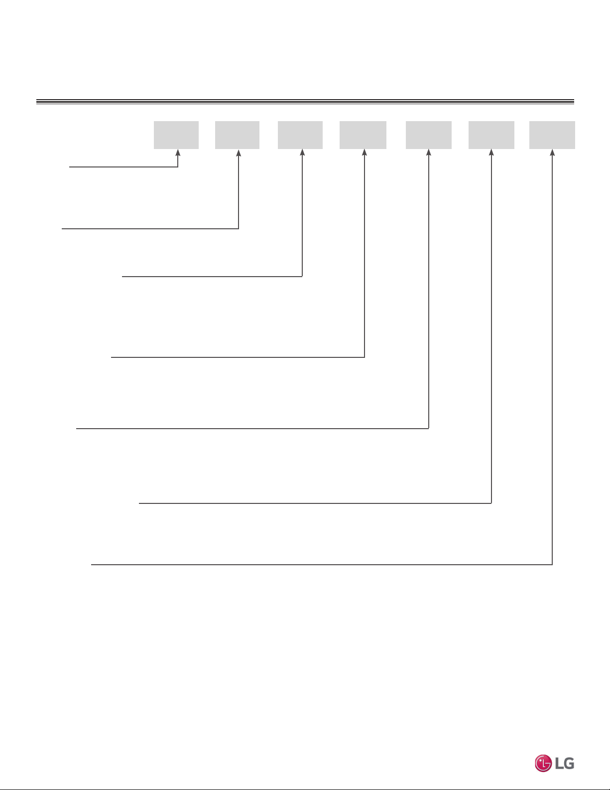
Unit Nomenclature................................................................................. 8
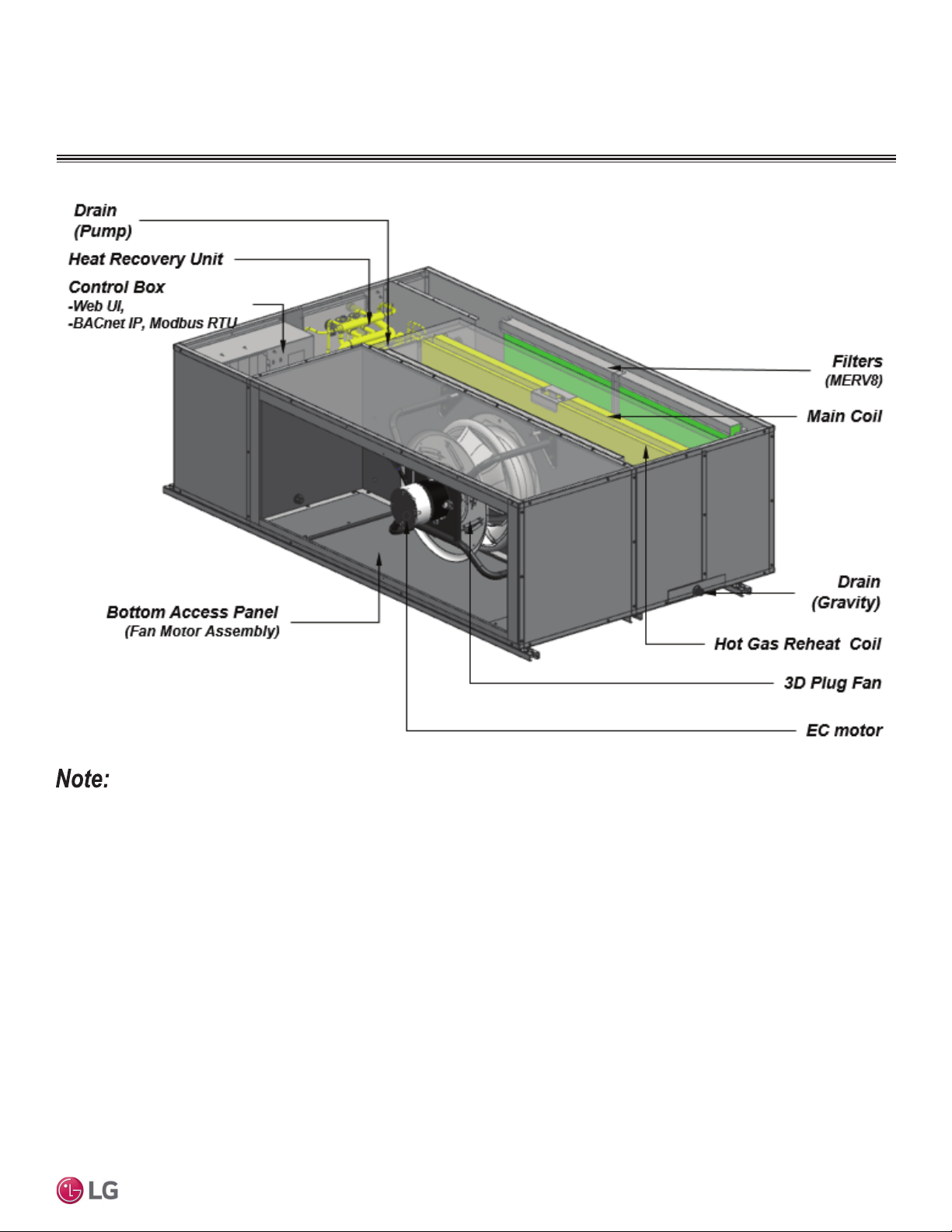
Product Overview.............................................................................9-10
Interior Components............................................................................ 9
Electrical Components....................................................................... 10
General Data ................................................................................... 11-20
6SHFL¿FDWLRQV .................................................................................... 11
Electrical............................................................................................ 12
External Dimensions.....................................................................13-14
Wiring ...........................................................................................15-16
Refrigerant Flow - Cooling................................................................. 17
5HIULJHUDQW)ORZ'HKXPLGL¿FDWLRQ .................................................. 18
Refrigerant Flow - Heating................................................................. 19
Sound Power Levels.......................................................................... 20
Installation.......................................................................................21-25
Receiving........................................................................................... 21
Handling ............................................................................................ 21
Storage / Removing........................................................................... 21
Assemblies ........................................................................................ 21
$LUÀRZ$UUDQJHPHQW .......................................................................... 21
Location Selection ............................................................................. 22
Roughing In ....................................................................................... 22
Mounting Dimensions........................................................................ 23
'XFWZRUN&RQ¿JXUDWLRQ ..................................................................... 23
Service Clearances ........................................................................... 24
Piping Connections............................................................................ 24
Field-Installed Outdoor Air (OA) Filter ............................................... 25
Unit Piping.......................................................................................26-31
Refrigerant Safety ............................................................................. 26
Piping Handling ................................................................................. 26
Brazing Procedure............................................................................. 27
Pipe Support Location ...................................................................... 27
Insulate.............................................................................................. 27
Condensate Drain Connections......................................................... 28
Condensate Pump Connection.......................................................... 28
Unit Drain Information........................................................................ 28
Gravity Condensate Pipe Connection ............................................... 29
Installing the Condensate Drain Pipe ................................................ 29
Refrigerant Piping Installation............................................................ 30
Refrigerant System Eng., Allowable Pipe Length.............................. 30
Sample Layout................................................................................... 31
Conditional Applications .................................................................... 31
Electrical Information.....................................................................32-39
General Information........................................................................... 32
Separating Power Wiring and Communication Cables...................... 32
Power Wiring ..................................................................................... 33
Communication Cable Connections .................................................. 33
Terminal Connections ........................................................................ 33
3RZHU6XSSO\3RZHU:LULQJ6SHFL¿FDWLRQV..................................... 34
Communication Cable Specs. from ODU to DOAS........................... 35
Connection Procedure....................................................................... 36
Field Wiring........................................................................................ 37
Field-Mounted Sensors ................................................................38-39
Leak Pressure Check / Evacuation...............................................40-44
Leak / Pressure Check .................................................................40-41
Ambient Conditions ........................................................................... 41
Evacuation....................................................................................42-44
Charging Refrigerant........................................................................... 45
Refrigerant Charge Worksheet.......................................................... 45
6WDUWXS&RQÀJXUDWLRQ ......................................................................... 46
Checks Before Initial Startup............................................................. 46
Electric Preheater Accessory........................................................47-63
Safety Precautions .......................................................................47-49
Overview............................................................................................ 50
General Data ..................................................................................... 51
Dimensions...................................................................................52-53
Wiring Diagram.............................................................................54-55
Installation Procedure...................................................................56-58
Sequence Setting .........................................................................59-63
Controller ........................................................................................64-85
Overview............................................................................................ 64
(OHFWULFDO6SHFL¿FDWLRQV..................................................................... 64
Connecting to the Web UI ................................................................. 64
Service Password ............................................................................. 65
Startup Settings................................................................................. 65
IP Address ......................................................................................... 65
DOAS Unit Address Setting............................................................... 65
Central Controller Setting .................................................................. 66
AC Smart / ACP Controller Setup.................................................67-68
%06&RQ¿JXUDWLRQ ............................................................................ 69
Main Control Board Terminal Connections ....................................... 70
CAREL Control Board Terminal Connections .................................... 70
LG Control Board Layout................................................................... 71
UI Module .......................................................................................... 72
NTC Module ...................................................................................... 73
EEV Module....................................................................................... 74
Navigation.....................................................................................75-77
Software Update................................................................................ 78
BACnet / Modbus Object List .......................................................79-85
Installation Checklist......................................................................86-87

4
Split Compact Dedicated Outdoor Air System Installation Manual
Due to our policy of continuous product innovation, some specifications may change without notification.
©LG Electronics U.S.A., Inc., Englewood Cliffs, NJ. All rights reserved. “LG” is a registered trademark of LG Corp.
The instructions below must be followed to prevent product malfunction, property damage, injury or death to the user or other people. Incor-
rect operation due to ignoring any instructions will cause harm or damage. The level of seriousness is classified by the symbols below.
WARNING
Do not install or remove the unit by yourself
(end-user). Ask the dealer or an LG trained technician to
install the unit.
,PSURSHULQVWDOODWLRQE\WKHXVHUPD\UHVXOWLQZDWHUOHDNDJH¿UH
explosion, which will result in electric shock, physical injury or death.
Installation, startup, and service must be performed by a
TXDOL¿HGLQVWDOOHUVHUYLFHDJHQF\RUJDVVXSSOLHU
Improper installation, adjustment, service, maintenance, or alteration
can cause personal injury or loss of life.
For replacement of an installed unit, always contact a
trained service provider.
7KHUHLVULVNRI¿UHHOHFWULFVKRFNH[SORVLRQZKLFKZLOOUHVXOWLQSK\VLFDO
injury or death.
Periodically check that the unit is not damaged.
There is risk of explosion, which will result in physical injury, or death.
Replace all control box and panel covers.
If cover panels are not installed securely, dust, water and animals may
HQWHUWKHXQLWFDXVLQJ¿UHHOHFWULFVKRFNZKLFKZLOOUHVXOWLQSK\VLFDO
injury or death.
Always check for system refrigerant leaks after the unit has
been installed or serviced.
Exposure to high concentration levels of refrigerant gas may lead to
illness or death.
Do not install the unit using defective hanging, attaching,
or mounting hardware.
There is risk of physical injury or death.
Wear protective gloves when handling equipment.
Sharp edges may cause personal injury.
Dispose of the packing materials safely.
• Packing materials, such as nails and other metal or wooden parts
may cause puncture wounds or other injuries.
• Tear apart and throw away plastic packaging bags so that children
may not play with them and risk suffocation and death.
Do not install the unit in any location exposed to open
ÀDPHRUH[WUHPHKHDW Do not touch the unit with wet
hands.
7KHUHLVULVNRI¿UHHOHFWULFVKRFNH[SORVLRQZKLFKZLOOUHVXOWLQSK\VLFDO
injury or death.
Install the unit considering the potential for earthquakes.
Improper installation may cause the unit to fall, resulting in physical
injury or death.
Do not change the settings of the protection devices.
If the pressure switch, thermal switch, or other protection device is short-
HGDQGIRUFHGWRRSHUDWHLPSURSHUO\RUSDUWVRWKHUWKDQWKRVHVSHFL¿HG
E\/*DUHXVHGWKHUHLVULVNRI¿UHHOHFWULFVKRFNH[SORVLRQUHVXOWLQJLQ
physical injury or death.
If the unit is installed in a small space, take measures to
prevent the refrigerant concentration from exceeding safety
limits in the event of a refrigerant leak.
Consult the latest edition of ASHRAE®(American Society of Heating,
Refrigerating, and Air Conditioning Engineers) Standard 15. If the re-
frigerant leaks and safety limits are exceeded, it could result in personal
injuries or death from oxygen depletion.
(The name “ASHRAE” and the ASHRAE logo are trademarks of the American Society of
Heating, Refrigerating, and Air-Conditioning Engineers, Inc.)
INSTALLATION
DANGER
'RQRWXVHRUVWRUHÀDPPDEOHJDVRUFRPEXVWLEOHVQHDU
the unit.
7KHUHLVULVNRU¿UHRUH[SORVLRQZKLFKZLOOUHVXOWLQGHDWKRUVHULRXVLQMXU\
Do not supply power to the unit until all wiring and piping
are completed or reconnected and checked.
There is risk of physical injury or death due to electric shock.
TABLE OF SYMBOLS
SAFETY PRECAUTIONS
DANGER This symbol indicates an imminently hazardous situation which, if not avoided, will result in death or serious injury.
WARNING This symbol indicates a potentially hazardous situation which, if not avoided, could result in death or serious injury.
CAUTION This symbol indicates a potentially hazardous situation which, if not avoided, may result in minor or moderate injury.
This symbol indicates situations that may result in equipment or property damage accidents only.
This symbol indicates information related to the current procedure.
This symbol indicates an action that should not be performed.
NOTE

5
Safety Precautions
Due to our policy of continuous product innovation, some specifications may change without notification.
©LG Electronics U.S.A., Inc., Englewood Cliffs, NJ. All rights reserved. “LG” is a registered trademark of LG Corp.
CAUTION
Be very careful when transporting the product.
•Do not attempt to carry the product without assistance.
• Some products use polypropylene bands for packaging. Do not use polypropylene bands to lift the unit.
• Suspend the unit from the base at specified positions.
• Support the unit at a minimum of four points to avoid slippage from rigging apparatus.
• Failure to follow these directions may result in minor or moderate physical injury.
INSTALLATION – CONTINUED
NOTE
Installation, startup, and service must be performed by a
TXDOL¿HGLQVWDOOHUVHUYLFHDJHQF\RUJDVVXSSOLHU
Improper installation, adjustment, service, maintenance, or alteration can
cause property damage.
Properly insulate all cold surfaces to prevent “sweating.”
Cold surfaces such as uninsulated pipe can generate condensate that
PD\GULSDQGFDXVHDVOLSSHU\ÀRRUFRQGLWLRQDQGRUZDWHUGDPDJHWR
walls.
When installing the unit in a hospital, mechanical room, or
VLPLODUHOHFWURPDJQHWLF¿HOG(0)VHQVLWLYHHQYLURQPHQW
SURYLGHVXႈFLHQWSURWHFWLRQDJDLQVWHOHFWULFDOQRLVH
Inverter equipment, power generators, high-frequency medical equip-
ment, or radio communication equipment may cause the air conditioner
to operate improperly. The unit may also affect such equipment by
creating electrical noise that disturbs medical treatment or image broad-
casting.
Do not use the product for special purposes such as pre-
serving foods, works of art, wine coolers, or other precision
air conditioning applications.
There is risk of property damage.
Do not make refrigerant substitutions. Use R410A only.
If a different refrigerant is used, or air mixes with original refrigerant, the
unit will malfunction and become damaged.
Do not install the unit in a noise sensitive area.
When connecting refrigerant tubing, remember to allow for
pipe expansion.
Improper piping may cause refrigerant leaks and system malfunction.
Take appropriate actions at the end of HVAC equipment life
to recover, recycle, reclaim or destroy R410A refrigerant ac-
cording to applicable U.S. Environmental Protection Agency
(EPA) rules.
Periodically check that the outdoor unit is not damaged.
There is a risk of equipment damage.
Install the unit in a safe location where no one can step on or
fall onto it.
There is risk of unit and property damage.
Install the drain trap to ensure adequate drainage.
There is a risk of water leakage and property damage.
'RQ¶WVWRUHRUXVHÀDPPDEOHJDVFRPEXVWLEOHVQHDUWKH
unit.
There is risk of product failure.
Always check for system refrigerant leaks after the unit has
been installed or serviced.
Low refrigerant levels may cause product failure.
'XFWZRUNDQGRWKHULQVWDOOHGDLUÀRZUHVWULFWLRQGHYLFHVVXFK
DV¿OWHUVVKDOOQRWH[FHHGWKHUDWHGPD[LPXPVWDWLFSUHVVXUH
limits of the DOAS fan assembly.
Doing so may cause product malfunction.
OA Inlet (duct) should not be placed in an environment where
may be exposed to harmful volatile organic compounds
(VOCs), or in environments where there is improper air make
up or supply or inadequate ventilation.
SAFETY PRECAUTIONS

6
Split Compact Dedicated Outdoor Air System Installation Manual
Due to our policy of continuous product innovation, some specifications may change without notification.
©LG Electronics U.S.A., Inc., Englewood Cliffs, NJ. All rights reserved. “LG” is a registered trademark of LG Corp.
WIRING
DANGER
High voltage electricity is required to operate this system.
Adhere to the National Electrical Codes and these
instructions when wiring.
Improper connections and inadequate grounding will cause accidental
injury or death.
Always ground the unit following local, state, and National
Electrical Codes.
7XUQWKHSRZHURႇDWWKHQHDUHVWGLVFRQQHFWEHIRUHVHUYLFLQJ
the equipment.
Electric shock will cause physical injury or death.
Properly size all circuit breakers or fuses.
7KHUHLVULVNRI¿UHHOHFWULFVKRFNH[SORVLRQUHVXOWLQJLQSK\VLFDOLQMXU\
or death.
WARNING
The information contained in this manual is intended for use
by an experienced, trained electrician familiar with the U.S.
National Electric Code (NEC) who is equipped with the proper
tools and test instruments.
Failure to carefully read and follow all instructions in this manual can
result in injury or death.
Ensure the unit is connected to a dedicated power source
that provides adequate power.
If the power source capacity is inadequate or the electric work is not
SHUIRUPHGSURSHUO\LWPD\FDXVH¿UHHOHFWULFVKRFNUHVXOWLQJLQSK\VLFDO
injury or death.
Refer to local, state, and federal codes, and use power wires
RIVXႈFLHQWFXUUHQWFDSDFLW\DQGUDWLQJ
:LUHVWKDWDUHWRRVPDOOPD\JHQHUDWHKHDWDQGFDXVHD¿UHUHVXOWLQJLQ
physical injury or death.
6HFXUHDOO¿HOGZLULQJFRQQHFWLRQVZLWKDSSURSULDWHZLUH
strain relief.
Improperly securing wires will create undue stress on equipment power
OXJV,QDGHTXDWHFRQQHFWLRQVPD\JHQHUDWHKHDWFDXVHD¿UHUHVXOWLQJ
in physical injury or death.
Properly tighten all power connections.
/RRVHZLULQJPD\RYHUKHDWDWFRQQHFWLRQSRLQWVFDXVLQJD¿UHUHVXOWLQJ
in physical injury or death.
NOTE
The information contained in this manual is intended for use
by an experienced, trained electrician familiar with the U.S.
National Electric Code (NEC) who is equipped with the proper
tools and test instruments.
Failure to carefully read and follow all instructions in this manual can
result in equipment malfunction or property damage.
Do not supply power to the unit until all electrical wiring,
controls wiring, piping, installation, and refrigerant system
evacuation are completed.
The system will malfunction.
SAFETY PRECAUTIONS

7
Safety Precautions
Due to our policy of continuous product innovation, some specifications may change without notification.
©LG Electronics U.S.A., Inc., Englewood Cliffs, NJ. All rights reserved. “LG” is a registered trademark of LG Corp.
OPERATION
DANGER
'RQRWSURYLGHSRZHUWRRURSHUDWHWKHXQLWLILWLVÀRRGHG
or submerged.
7KHUHLVULVNRI¿UHHOHFWULFVKRFNUHVXOWLQJLQSK\VLFDOLQMXU\RUGHDWK
Use a dedicated power source for this product.
7KHUHLVULVNRI¿UHHOHFWULFVKRFNUHVXOWLQJLQSK\VLFDOLQMXU\RUGHDWK
Do not operate the disconnect switch with wet hands.
7KHUHLVULVNRI¿UHHOHFWULFVKRFNUHVXOWLQJLQSK\VLFDOLQMXU\RUGHDWK
Periodically verify the hanging bolts and other hardware
securing the unit have not deteriorated.
If the unit falls from its installed location, it will cause property damage,
product failure,resulting in physical injury or death.
If refrigerant gas leaks out, ventilate the area before operat-
ing the unit.
If the unit is mounted in an enclosed, low-lying, or poorly ventilated area
DQGWKHV\VWHPGHYHORSVDUHIULJHUDQWOHDNLWZLOOFDXVH¿UHHOHFWULF
shock, explosion, resulting in physical injury or death.
NOTE
&OHDQXSWKHVLWHDIWHULQVWDOODWLRQLV¿QLVKHGDQGFKHFN
that no metal scraps, screws, or bits of wiring have been left
inside or surrounding the unit.
Do not use this equipment in mission critical or special-
purpose applications such as preserving foods, works of art,
wine coolers or refrigeration.
Provide power to the compressor crankcase heaters to ap-
plication outdoor units at least six (6) hours before operation
begins.
Starting operation with a cold compressor sump(s) may result in severe
bearing damage to the compressor(s). Keep the power switch on during
the operational season.
Do not operate the unit with the panel(s) or protective
FRYHUVUHPRYHGNHHS¿QJHUVDQGFORWKLQJDZD\IURP
moving parts.
Non-secured covers can result in equipment malfunction due to dust or
water.
Do not block the inlet or outlet.
Unit may malfunction.
Securely attach the electrical cover to the unit.
1RQVHFXUHGFRYHUVFDQUHVXOWLQ¿UHGXHWRGXVWRUZDWHULQWKHVHUYLFH
panel.
Periodically verify the equipment mounting hardware has not
deteriorated.
If the base collapses, the unit could fall and cause property damage or
product failure.
Do not allow water, dirt, or animals to enter the unit.
There is risk of unit failure.
'RQRWWXUQRႇWKHPDLQSRZHUVZLWFKDIWHURSHUDWLRQKDV
been stopped.
:DLWDWOHDVW¿YHPLQXWHVEHIRUHWXUQLQJRIIWKHPDLQSRZHUVZLWFK
otherwise it will result in product malfunction.
WARNING
Do not allow water, dirt, or animals to enter the unit.
7KHUHLVULVNRI¿UHHOHFWULFVKRFNUHVXOWLQJLQSK\VLFDOLQMXU\RUGHDWK
Do not touch refrigerant piping during or after operation.
It can cause burns or frostbite.
Do not operate the unit with the panel(s) or protective
FRYHUVUHPRYHGNHHS¿QJHUVDQGFORWKLQJDZD\IURP
moving parts.
The rotating, hot, cold, and high-voltage parts of the unit can cause
physical injury or death.
Periodically check power cable and connection for damage.
Cable must be replaced by the manufacturer, its service agent, or similar
TXDOL¿HGSHUVRQVLQRUGHUWRDYRLGSK\VLFDOLQMXU\DQGRUHOHFWULFVKRFN
Securely attach the electrical cover to the unit.
Non-secured electrical covers can result in burns or electric shock due to
dust or water in the service panel.
Ensure no power is connected to the unit other than as
directed in this manual. Remove power from the unit before
removing or servicing the unit.
7KHUHLVULVNRIXQLWIDLOXUH¿UHHOHFWULFVKRFNUHVXOWLQJLQSK\VLFDOLQMXU\
or death.
CAUTION
To avoid physical injury, use caution when cleaning or servicing the unit.
SAFETY PRECAUTIONS

8
Split Compact Dedicated Outdoor Air System Installation Manual
Due to our policy of continuous product innovation, some specifications may change without notification.
©LG Electronics U.S.A., Inc., Englewood Cliffs, NJ. All rights reserved. “LG” is a registered trademark of LG Corp.
UNIT NOMENCLATURE
ARN D20 3DC
Air Flow Rate (CFM)
90 = 900 CFM
15 = 1,500 CFM
20 = 2,000 CFM
Type
D = Dedicated Outdoor Air System (DOAS)
Family
ARN = Multi V Indoor Unit
R410A Refrigerant
4
Generation
4 = Fourth
Chassis
DB = Type B (Rooftop DOAS)
DC = Type C (Compact DOAS)
R
Energy Recovery Wheel
R = Without Energy Recovery Wheel
Electrical Ratings
U = 208-230V / 460V, 60Hz, 3 Phase
3 = 208-220V, 60Hz, 1 Phase

9
Product Overview
Due to our policy of continuous product innovation, some specifications may change without notification.
©LG Electronics U.S.A., Inc., Englewood Cliffs, NJ. All rights reserved. “LG” is a registered trademark of LG Corp.
PRODUCT OVERVIEW
Interior Components
Top panel can be removed to access the 3D Plug Fan.

10
Split Compact Dedicated Outdoor Air System Installation Manual
Due to our policy of continuous product innovation, some specifications may change without notification.
©LG Electronics U.S.A., Inc., Englewood Cliffs, NJ. All rights reserved. “LG” is a registered trademark of LG Corp.
Electrical Components
Table 1: Electrical Components Legend.
Electrical Component No. Description
1CAREL®Controller
2 Main Module
3 UI Module
4 NTC Module
5 Main Coil EEV Module
6 Reheat Coil EEV Module
7 Heat Recovery Unit PCB
8SMPS
9 Transformer
10 RS-485 1
11 RS-485 2
12 Relay 1
13 Relay 2
PRODUCT OVERVIEW
The CAREL®name and logo are registered trademarks and distinctive marks of CAREL
INDUSTRIES S.p.A.

11
General Data
Due to our policy of continuous product innovation, some specifications may change without notification.
©LG Electronics U.S.A., Inc., Englewood Cliffs, NJ. All rights reserved. “LG” is a registered trademark of LG Corp.
GENERAL DATA
Table 2: Split Compact DOAS General Data.
Actual discharge air temperatures may vary from discharge air temperature set-point due to changes in outdoor air processing loads.
EEV - Electronic Expansion Valve
ECM - Electronically Commutated Motor
Power Supply (V/Hz/Ø): 208-230/60/1
3RZHUZLULQJLV¿HOGVXSSOLHGDQGPXVWFRPSO\ZLWKWKHDSSOLFDEOHORFDODQGQDWLRQDO
codes.
This data is rated 0 ft. above sea level, with 25 ft. of refrigerant piping per coil.
Main Coil Cooling Capacity Rating obtained with entering air of 95°F D.B. / 75°F W.B. and
leaving air of 52.9°F D.B. / 52.5°F W.B.
Main Coil Heating Capacity Rating obtained with entering air of 44°F D.B. and leaving air
of 70°F D.B.
Reheat Coil Heating Capacity Rating obtained with entering air of 54°F D.B. and leaving
air of 75°F D.B.
1Take appropriate actions at the end of HVAC equipment life to recover, recycle, reclaim or
destroy R410A refrigerant according to applicable regulations (40 CFR Part 82, Subpart F)
under section 608 of CAA.
2Sound power levels are tested under AHRI 260 Standard.
3All communication cable from the outdoor unit to the DOAS unit is to be minimum 18 AWG,
2 (2 conductor), twisted, stranded, shielded and must comply with applicable local and na-
tional codes. Ensure the communication cable is properly grounded at the outdoor unit only.
Do not ground the outdoor unit -DOAS unit communication cable at any other point.
410°F entering air temperature is allowed for 1,500 CFM or less with minimum 12-ton out-
door unit for one (1) DOAS connected to one (1) outdoor unit, and minimum 30-ton outdoor
unit for two (2) DOAS units connected to (1) outdoor unit. Maximum number of two (2)
DOAS units may be connected to one (1) outdoor unit with 10°F entering air temperature.
5Both the ARND153DCR4 and the ARND203DCR4 can provide CFM as low as 900 CFM.
For a 900 CFM application, the unit requires a 1-to-1 combination with an LG MV 5 Heat
Recovery 6-ton or 8-ton outdoor unit.
6SHFL¿FDWLRQV
Unit Model No. ARND093DCR4 ARND153DCR4 ARND203DCR4
Cooling Mode Performance
Total Cooling Capacity (Btu/h) 70,000 120,000 143,100
Hot Gas Reheat Capacity (Btu/h) 13,000 24,000 30,000
Moisture Removal Capacity (lb. / h) 33.0 55.0 67
Heating Mode Performance
Capacity (Btu/h) (Main Coil) 40,000 51,000 59,900
Entering Air
Cooling Maximum (°F, D.B. / W.B.) 122 / 80 122 / 80 122 / 80
Heating Minimum (°F, D.B.) 14 (104) 14 14
Unit Data
Refrigerant Type1R410A R410A R410A
Refrigerant Control EEV EEV EEV
Sound Power dB(A)260 74 72
Net Unit Weight (lbs.) 342 390 390
Shipping Weight (lbs.) 381 430 430
Communication Cable3 (No. x AWG) 2 (2 conductor) x 18 2 (2 conductor) x 18 2 (2 conductor) x 18
Fan
Type Sirocco 3D Plug 3D Plug
Motor (HP / W) 0.33 / 250 1 / 750 1 / 750
Motor / Drive ECM / Direct ECM / Direct ECM / Direct
Airflow Rate (CFM) 900 1,500 2,000
External Static Pressure (in. w.g.) 1.0 2.0 1.5
Airflow Range (CFM) 500-900 1,0005– 1,500 1,0005– 2,000
Piping
Liquid Connection Size (in., O.D.) 3/8 Brazed 1/2 Brazed 1/2 Brazed
High Pressure Vapor Connection Size (in., O.D.) 5/8 Brazed 3/4 Brazed 7/8 Brazed
Low Pressure Vapor Connection Size (in., O.D.) 3/4 Brazed 1-1/8 Brazed 1-1/8 Brazed
Condensate Drain (in.) Drain Pump (in., I.D.) 111
Gravity (in.,O.D.) 111
Filter
Outdoor 2”Merv 8 (25”x 20”)2"Merv 8 (25"x 20")2"Merv 8 (25"x 20")

12
Split Compact Dedicated Outdoor Air System Installation Manual
Due to our policy of continuous product innovation, some specifications may change without notification.
©LG Electronics U.S.A., Inc., Englewood Cliffs, NJ. All rights reserved. “LG” is a registered trademark of LG Corp.
Table 3: Split Compact DOAS Electrical Data
MCA : Minimum Circuit Ampacity. MOP : Maximum Overcurrent Protection: (Largest motor FLA x 2.25) + (Sum of other motor
FLA) rounded down to the nearest standard fuse size.
Electrical
GENERAL DATA
Model Power Supply FLA MCA MOP
Hz Volts Voltage Range Phase
ARND093DCR4
60 208-230 187-253 1
2.0 2.5 15
ARND153DCR4 5.8 7.3 15
ARND203DCR4 6.0 7.5 15

13
General Data
Due to our policy of continuous product innovation, some specifications may change without notification.
©LG Electronics U.S.A., Inc., Englewood Cliffs, NJ. All rights reserved. “LG” is a registered trademark of LG Corp.
GENERAL DATA
ARND093DCR4 External Dimensions
16.46
48.92
77.24
76.22
9.83
6.54
Drain Line
(Gravity)
Fan Motor Assembly Section
OA Filter Section
Control Box Section
Cycle Section
OA Filter Section
Low Pressure Vapor Line
High Pressure Vapor Line
Liquid Line
Drain Line(Drain Pump)
Ø1.2 Wiring Entry
10.57
9.25
11.66
11.96
14.72
18.07
14.28
1.41
46.22
37.36
23.23
22.26 7.39
12.06 4.53
Unit: Inch

14
Split Compact Dedicated Outdoor Air System Installation Manual
Due to our policy of continuous product innovation, some specifications may change without notification.
©LG Electronics U.S.A., Inc., Englewood Cliffs, NJ. All rights reserved. “LG” is a registered trademark of LG Corp.
GENERAL DATA
Unit: Inch
ARND153DCR4, ARND203DCR4 External Dimensions

15
General Data
Due to our policy of continuous product innovation, some specifications may change without notification.
©LG Electronics U.S.A., Inc., Englewood Cliffs, NJ. All rights reserved. “LG” is a registered trademark of LG Corp.
GENERAL DATA
Wiring
Figure 1: ARND093DCR4 Wiring Diagram.
* This function can be
optional or factory installed
depending on the application
model.
* Optional parts must be
purchased separately. 5/22

16
Split Compact Dedicated Outdoor Air System Installation Manual
Due to our policy of continuous product innovation, some specifications may change without notification.
©LG Electronics U.S.A., Inc., Englewood Cliffs, NJ. All rights reserved. “LG” is a registered trademark of LG Corp.
GENERAL DATA
Wiring
Figure 2: ARND153DCR4, ARND203DCR4 Wiring Diagram.

17
General Data
Due to our policy of continuous product innovation, some specifications may change without notification.
©LG Electronics U.S.A., Inc., Englewood Cliffs, NJ. All rights reserved. “LG” is a registered trademark of LG Corp.
Refrigerant Flow - Cooling
Figure 3: ARND093DCR4, ARND153DCR4, and ARND203DCR4 Refrigerant Piping Diagram (Cooling)
GENERAL DATA
M
EEV
Sirroco Fan (ARND093DCR4) or
3D Plug Fan (ARND153DCR4, ARND203DCR4)
Filter EEV
EEV
Main coil
TH1 HUMID1
Reheat coil EEV
TH2
TH3 TH4
TH5
TH6
TH7
TH8
TH9 TH10
TH11 TH12
Airflow
Airflow
TH1 ~TH5 : Air Thermistor
TH6 ~TH12 : Pipe Thermistor
Humid1 : Air Humidity Sensor
High Temperature High Pressure Vapor
Low Temperature Low Pressure Vapor
High Temperature High Pressure Liquid
Check ValveSolenoid valve Filter Muffler
Table 4: ARND093DCR4, ARND153DCR4, and ARND203DCR4 Refrigerant Pipe Connection Port Diameters.
Thermistor Type Description
TH1 Air Outdoor Air Thermistor
TH2 Air Mixed Air Thermistor (After E/Heater)
TH3 Air Main Coil 1 Thermistor
TH4 Air Main Coil 2 Thermistor
TH5 Air Supply Air Thermistor
TH6 Pipe Liquid Pipe Thermistor
TH7 Pipe SC In Thermistor
TH8 Pipe SC Out Thermistor
TH9 Pipe Main Coil In Thermistor
TH10 Pipe Main Coil Out Thermistor
TH11 Pipe Reheat Coil In Thermistor
TH12 Pipe Reheat Coil Out Thermistor
Humid1 - Outdoor Air Humidity Sensor
Model Liquid (in., O.D.) High Pressure Vapor (in., O.D.) Low Pressure Vapor Size (in., O.D.)
ARND093DCR4 3/8 Brazed 5/8 Brazed 3/4 Brazed
ARND153DCR4 1/2 Brazed 3/4 Brazed 1-1/8 Brazed
ARND203DCR4 1/2 Brazed 7/8 Brazed 1-1/8 Brazed
Table 5: ARND093DCR4, ARND153DCR4, and ARND203DCR4 Thermistors.

18
Split Compact Dedicated Outdoor Air System Installation Manual
Due to our policy of continuous product innovation, some specifications may change without notification.
©LG Electronics U.S.A., Inc., Englewood Cliffs, NJ. All rights reserved. “LG” is a registered trademark of LG Corp.
Figure 4: $51''&5$51''&5DQG$51''&55HIULJHUDQW3LSLQJ'LDJUDP'HKXPLGL¿FDWLRQ
5HIULJHUDQW)ORZ'HKXPLGL¿FDWLRQ
GENERAL DATA
M
EEV
Filter EEV
EEV
Main coil
TH1 HUMID1
Reheat coil EEV
TH2
TH3 TH4
TH5
TH6
TH7
TH8
TH9 TH10
TH11 TH12
Airflow
Airflow
TH1 ~TH5 : Air Thermistor
TH6 ~TH12 : Pipe Thermistor
Humid1 : Air Humidity Sensor
High Temperature High Pressure Vapor
Low Temperature Low Pressure Vapor
High Temperature High Pressure Liquid
Check ValveSolenoid Valve Filter
Muffler
Sirroco Fan (ARND093DCR4) or
3D Plug Fan (ARND153DCR4, ARND203DCR4)
Table 6: ARND093DCR4, ARND153DCR4, and ARND203DCR4 Refrigerant Pipe Connection Port Diameters.
Thermistor Type Description
TH1 Air Outdoor Air Thermistor
TH2 Air Mixed Air Thermistor (After E/Heater)
TH3 Air Main Coil 1 Thermistor
TH4 Air Main Coil 2 Thermistor
TH5 Air Supply Air Thermistor
TH6 Pipe Liquid Pipe Thermistor
TH7 Pipe SC In Thermistor
TH8 Pipe SC Out Thermistor
TH9 Pipe Main Coil In Thermistor
TH10 Pipe Main Coil Out Thermistor
TH11 Pipe Reheat Coil In Thermistor
TH12 Pipe Reheat Coil Out Thermistor
Humid1 - Outdoor Air Humidity Sensor
Table 7: ARND093DCR4, ARND153DCR4, and ARND203DCR4 Thermistors.
Model Liquid (in., O.D.) High Pressure Vapor (in., O.D.) Low Pressure Vapor Size (in., O.D.)
ARND093DCR4 3/8 Brazed 5/8 Brazed 3/4 Brazed
ARND153DCR4 1/2 Brazed 3/4 Brazed 1-1/8 Brazed
ARND203DCR4 1/2 Brazed 7/8 Brazed 1-1/8 Brazed

19
General Data
Due to our policy of continuous product innovation, some specifications may change without notification.
©LG Electronics U.S.A., Inc., Englewood Cliffs, NJ. All rights reserved. “LG” is a registered trademark of LG Corp.
Figure 5: ARND093DCR4, ARND153DCR4, and ARND203DCR4 Refrigerant Piping Diagram (Heating).
Refrigerant Flow - Heating
GENERAL DATA
M
EEV
Filter EEV
EEV
Main coil
TH1 HUMID1
Reheat coil EEV
TH2
TH3 TH4
TH5
TH6
TH7
TH8
TH9 TH10
TH11 TH12
Airflow
Airflow
TH1 ~TH5 : Air Thermistor
TH6 ~TH12 : Pipe Thermistor
Humid1 : Air Humidity Sensor
High Temperature High Pressure Vapor
Low Temperature Low Pressure Vapor
High Temperature High Pressure Liquid
Check ValveSolenoid Valve Filter
Muffler
Sirroco Fan (ARND093DCR4) or
3D Plug Fan (ARND153DCR4, ARND203DCR4)
Table 8: ARND093DCR4, ARND153DCR4, and ARND203DCR4 Refrigerant Pipe Connection Port Diameters.
Thermistor Type Description
TH1 Air Outdoor Air Thermistor
TH2 Air Mixed Air Thermistor (After E/Heater)
TH3 Air Main Coil 1 Thermistor
TH4 Air Main Coil 2 Thermistor
TH5 Air Supply Air Thermistor
TH6 Pipe Liquid Pipe Thermistor
TH7 Pipe SC In Thermistor
TH8 Pipe SC Out Thermistor
TH9 Pipe Main Coil In Thermistor
TH10 Pipe Main Coil Out Thermistor
TH11 Pipe Reheat Coil In Thermistor
TH12 Pipe Reheat Coil Out Thermistor
Humid1 - Outdoor Air Humidity Sensor
Table 9: ARND093DCR4, ARND153DCR4, and ARND203DCR4 Thermistors.
Model Liquid (in., O.D.) High Pressure Vapor (in., O.D.) Low Pressure Vapor Size (in., O.D.)
ARND093DCR4 3/8 Brazed 5/8 Brazed 3/4 Brazed
ARND153DCR4 1/2 Brazed 3/4 Brazed 1-1/8 Brazed
ARND203DCR4 1/2 Brazed 7/8 Brazed 1-1/8 Brazed

20
Split Compact Dedicated Outdoor Air System Installation Manual
Due to our policy of continuous product innovation, some specifications may change without notification.
©LG Electronics U.S.A., Inc., Englewood Cliffs, NJ. All rights reserved. “LG” is a registered trademark of LG Corp.
GENERAL DATA
Sound Power Levels
Sound Power Levels
Table 10: ARND093DCR4 500 CFM Sound Power Data (@0.2 ESP).
Model Rating E.S.P CFM Sound Power Level, Lw (dB one reference picowatt)
63Hz 125Hz 250Hz 500Hz 1kHz 2kHz 4kHz 8kHz
ARND153DCR4,
ARND203DCR4
Ducted Inlet
0.96 1,211
70.9 68.2 62.4 58.8 53.9 50.9 42.5 39.5
Casing Radiated 65.3 68.2 62.0 62.4 63.0 60.5 55.4 52.3
Ducted Outlet 71.3 68.2 67.0 64.1 66.3 61.0 48.8 43.5
Model Rating E.S.P CFM Sound Power Level, Lw (dB one reference picowatt)
63Hz 125Hz 250Hz 500Hz 1kHz 2kHz 4kHz 8kHz
ARND153DCR4
Ducted Inlet
1.96 1,516
76.9 72.1 71.7 68.7 61.7 58.7 52.7 49.8
Casing Radiated 76.9 79.6 71.1 69.3 69.7 67.8 65.0 63.2
Ducted Outlet 80.3 72.6 79.5 72.6 72.9 67.5 61.2 54.5
Model Rating E.S.P CFM Sound Power Level, Lw (dB one reference picowatt)
63Hz 125Hz 250Hz 500Hz 1kHz 2kHz 4kHz 8kHz
ARND203DCR4
Ducted Inlet
1.5 2,023
71.9 70.3 74.8 68.1 60.2 58.6 53.6 49.7
Casing Radiated 73.5 73.2 70.0 67.5 67.1 65.1 63.0 59.5
Ducted Outlet 72.5 77.3 82.9 72.7 72.3 67.4 60.5 54.7
Model Rating E.S.P CFM Sound Power Level, Lw (dB one reference picowatt)
63Hz 125Hz 250Hz 500Hz 1kHz 2kHz 4kHz 8kHz
ARND093DCR4
Ducted Inlet
0.2 500
39.8 47.5 51.7 57.6 56.8 51.9 45.2 32.5
Casing Radiated 33.5 35.8 40.9 50.0 47.2 43.8 36.3 25.8
Ducted Outlet 55.5 51.6 54.2 59.0 57.6 54.0 48.5 37.1
Model Rating E.S.P CFM Sound Power Level, Lw (dB one reference picowatt)
63Hz 125Hz 250Hz 500Hz 1kHz 2kHz 4kHz 8kHz
ARND093DCR4
Ducted Inlet
0.64 900
43.6 48.2 54.7 58.9 60.0 55.4 48.5 36.3
Casing Radiated 36.2 40.6 43.8 50.0 51.6 48.1 39.7 28.7
Ducted Outlet 70.9 66.8 58.8 62.1 62.7 59.6 56.1 48.0
Table 11: ARND093DCR4 900 CFM Sound Power Data (@0.64 ESP).
Table 12: ARND153DCR4 and ARND203DCR4 1,200 CFM Sound Data (@0.96 ESP).
Table 13: ARND153DCR4 1,500 CFM Sound Data (@1.96 ESP).
Table 14: ARND203DCR4 2,000 CFM Sound Data (@1.5 ESP).
Other manuals for ARND DCR4 Series
1
This manual suits for next models
1
Table of contents
Other LG Chiller manuals
Popular Chiller manuals by other brands

Hoshizaki
Hoshizaki LANCER Everest Installation, operation & service manual

Castel MAC
Castel MAC T3 user guide

Trane
Trane CenTraVac CVHM installation instructions

SMC Networks
SMC Networks HRR030-A-20 Series Operation manual

Carrier
Carrier 30HXC Series Installation, operation and maintenance instructions

Morgan
Morgan MCS-288D user manual