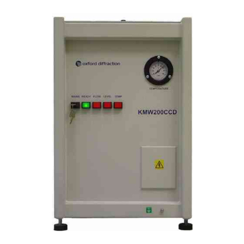
oxford diffraction KMW3000C User manual

User Manual
KMW3000C
Water Chiller Unit
October 2001
Version 1.1
Oxford Diffraction Limited
20 Nuffield Way, Abingdon
Oxon OX14 1RL UK
Tel: +44 (0)1235 532132
Fax: +44 (0)1235 528005
http://www.oxford-diffraction.com

KMW3000C Version 1
USER MANUAL KMW3000CChiller v1.1.doc Page ii
Important Information
This user manual is intended to help the user operate the KMW3000C water chiller unit
manufactured in Poland by Oxford Diffraction.
Product: KMW3000C
Model Type: X-ray tube / generator
Electrical Ratings: 1/N AC 230 V
50/60 Hz
300 Watts
Before attempting to operate the system, PLEASE READ THE
INSTRUCTIONS.
This product should only be used by persons legally permitted to do so.
If the equipment is used in a manner not specified in the User Manual, the protection provided by
the equipment may be impaired.
Important Health and Safety Notice
When returning components for service or repair it is essential that the item is shipped together with
a signed declaration that the product has not been exposed to any hazardous contamination or that
appropriate decontamination procedures have been carried out so that the product is safe to
handle.
Care has been taken to ensure the information in this manual is accurate and at an appropriate
level. Please inform Oxford Diffraction if you have any suggestions for corrections of improvements
to this manual.
This users' manual has been written according to standard 89/392/EEC and further modifications.
Oxford Diffraction acknowledges all trademarks and registrations.
Copyright 2000 Oxford Diffraction Limited. All rights reserved. No part of this document may be
reproduced or distributed in any form, or by any means, or stored in a database or retrieval system,
without prior written permission of Oxford Diffraction.

CONTENTS
KMW3000C Version 1
USER MANUAL KMW3000CChiller v1.1.doc Page iii
Contents
1. Health and Safety Information ........................................................1
1.1 General.................................................................................................................................... 1
1.2 Electrical Safety....................................................................................................................... 1
1.2.1 Potential Electrical Hazards ........................................................................................... 1
1.2.2 Recommended Precautions........................................................................................... 2
1.2.3 First Aid .......................................................................................................................... 2
1.3 Mechanical Handling Safety.................................................................................................... 2
1.4 Safe Mechanical Practice........................................................................................................ 3
1.5 Moving parts............................................................................................................................ 3
1.6 Modifications and Service ....................................................................................................... 3
2. Introduction ......................................................................................4
2.1 Scope ...................................................................................................................................... 4
2.2 How To Use This Manual........................................................................................................ 4
2.3 System Description ................................................................................................................. 4
3. Specifications...................................................................................5
3.1 Environment ............................................................................................................................ 5
3.2 Performance Data ................................................................................................................... 5
3.3 Electrical Services ................................................................................................................... 5
3.4 Water Supply........................................................................................................................... 5
4. Technical Description......................................................................6
4.1 Overview ................................................................................................................................. 6
4.2 Operating Principles ................................................................................................................ 6
4.2.1 Tap water circuit............................................................................................................. 6
4.2.2 Closed Circuit................................................................................................................. 7
4.2.3 Control Unit .................................................................................................................... 8
4.3 Interfaces................................................................................................................................. 8
4.3.1 Water Supply.................................................................................................................. 8
4.3.2 Electrical Connections....................................................................................................9
5. Handling, Installation, Storage and Transit Information ............10
5.1 Reception and Handling........................................................................................................ 10
5.1.1 Delivery ........................................................................................................................ 10
5.1.2 Unpacking .................................................................................................................... 10
5.1.3 Weights, Dimensions and Lifting Points....................................................................... 10
5.2 Installation and Setting to Work ............................................................................................ 11
5.2.1 Preparation of Site and Services ................................................................................. 11
5.2.1.1 Environmental Requirements ............................................................................. 11
5.2.1.2 System Layout .................................................................................................... 11
5.2.1.3 Electrical Services............................................................................................... 11
5.2.1.4 Water Supply ...................................................................................................... 11
5.2.2 Setting to Work............................................................................................................. 11
5.2.2.1 Equipment Required ........................................................................................... 12
5.2.2.2 Setting up Procedures ........................................................................................ 12
5.3 Storage............................................................................................................................ 13
6. Operating Instructions ..................................................................14

CONTENTS
KMW3000C Version 1
USER MANUAL KMW3000CChiller v1.1.doc Page iv
6.1 Warnings and Cautions......................................................................................................... 14
6.2 Controls and Indicators ......................................................................................................... 14
6.3 Switch-on Procedure (Manual).............................................................................................. 14
6.4 Switch-on Procedure (Remote)............................................................................................. 14
7. Maintenance Schedule ..................................................................15
7.1 Introduction............................................................................................................................ 15
7.2 Weekly Maintenance Schedule............................................................................................. 15
8. Maintenance Instructions..............................................................16
8.1 Filling The Reservoir With Water .................................................................................... 16
8.2 Cleaning The Water Filters ............................................................................................. 17
9. Trouble Shooting ...........................................................................18
10. Spares...........................................................................................19
11. Additional Information.................................................................20
11.1 Drawings ............................................................................................................................. 20
12. CE Conformity Notice..................................................................21

HEALTH AND SAFETY INFORMATION
KMW3000C Version 1
USER MANUAL KMW3000CChiller v1.1.doc Page 1
1. Health and Safety Information
1.1 General
In normal operation the system is designed to operate safely. All users of the KMW3000C water
chiller unit should be aware of potential hazards which exist in and around equipment of this type
and the ways of avoiding possible injury and equipment damage which may result from
inappropriate ways of working. A description of such potential hazards and how to avoid them is
given in this section.
This manual adopts the following convention:
WARNING
Indicates a potential hazard which may result in injury or death
CAUTION
Indicates a potential hazard which may result in damage to equipment
Warning symbols on the equipment have the following meanings:
Protective conductor terminal
Earth (ground) terminal
CAUTION
Risk of electric shock
CAUTION
Refer to accompanying documents
See original manufacturers' manuals for further safety data on third party equipment supplied with
the system. A list of these is given in this manual.
WARNING
Do not take risks. You have a responsibility to ensure the safe
condition and safe operation of equipment.
1.2 Electrical Safety
In normal use the user is protected from the dangers associated with the voltage, current and power
levels used by the equipment. Only suitably qualified personnel should attempt to disconnect,
dismantle or modify the equipment.
1.2.1 Potential Electrical Hazards
The following list is not intended as a complete guide to all the electrical hazards on the system, but
serves to illustrate the range of potential hazards that exist:
•electric shock
•electric burn

HEALTH AND SAFETY INFORMATION
KMW3000C Version 1
USER MANUAL KMW3000CChiller v1.1.doc Page 2
•fire of electrical origin
•electric arcing
1.2.2 Recommended Precautions
WARNING
All of the electrical equipment supplied as part of the system should
be provided with a protective ground. Do not remove protective
grounds as this may give rise to an electrical safety hazard. It is
vitally important that the system is properly grounded at all times.
Follow local and national electrical regulations and procedures.
Do not remove connectors, disconnect equipment, open safety
covers, dismantle or modify equipment unless you are qualified and
authorised to do so and you are fully conversant with its operation
and potential hazards or have total assurance through your local
electrical permit to work system that the equipment has been made
safe.
Make sure that the mains supply is fused at an appropriate rating and
that it can be isolated locally via a clearly labelled, clearly visible and
easily accessible isolating switch. Isolate the supply before carrying
out any maintenance work.
1.2.3 First Aid
A course in first aid to include methods of artificial respiration is recommended for those whose
work involves equipment which may produce a high voltage.
WARNING
Do not attempt to administer first aid to someone who may have
suffered electric shock until the source of the shock has been
isolated.
Mains voltages are present in the system. These can cause serious
injury or death.
Only personnel qualified and experienced to work with such currents
and voltages should perform service or maintenance work on this
equipment.
1.3 Mechanical Handling Safety
WARNING
Lifting points are provided for safe handling of components and safe
handling practice must be observed to comply with local regulations.
Check that lifting points are used only for the job intended.
The system itself and some components are heavy and require
careful handling. Use safe lifting procedures for heavy items to
prevent possible strain injury.

HEALTH AND SAFETY INFORMATION
KMW3000C Version 1
USER MANUAL KMW3000CChiller v1.1.doc Page 3
1.4 Safe Mechanical Practice
In normal use personnel are not required to undertake mechanical work. However, servicing or
repair may necessitate access to any part of the system. Only suitably qualified personnel should
attempt to dismantle, modify or repair equipment.
Water connections should be made and tested in accordance with any local and national safety
regulations.
1.5 Moving parts
There are a number of moving parts in the system which are powered by electric motors.
Warning
Injury could result if clothing or body parts become caught in moving
mechanisms.
Keep clothing, hands etc. away from moving mechanisms.
1.6 Modifications and Service
The manufacturer will not be held responsible for the safety, reliability or performance of the
equipment unless assembly operations, extensions, re-adjustments, modifications and repairs are
carried out only by persons authorised by the manufacturer. It should be stressed that those parts of
the equipment which are interchangeable, and which are subject to deterioration during operation,
may significantly affect the safety of the equipment.

INTRODUCTION
KMW3000C Version 1
USER MANUAL KMW3000CChiller v1.1.doc Page 4
2. Introduction
2.1 Scope
This manual applies to the KMW3000C water chiller unit manufactured by Oxford Diffraction.
2.2 How To Use This Manual
This manual is aimed at operators of the KMW3000C who are trained laboratory technicians and
have been trained to use the KMW3000C by Oxford Diffraction personnel.
This manual is intended to provide operators with a practical guide to the system and its operation.
This is intended to familiarise the operator with how the system works and provide a better
understanding of the system operation.
All personnel who are likely to operate the system or come into contact with any of the system
components should read the SAFETY section of the manual. This provides basic information aimed
at highlighting the safety hazards associated with the equipment.
The purpose of this manual is to:
•explain how to operate the equipment
•explain how to interface to the equipment
•list performance characteristics of the equipment
•describe how the equipment operates
•assist with simple fault finding and maintenance
2.3 System Description
The KMW3000C is a stand-alone chiller unit intended for indoor use. It is designed to be used to
cool X-ray generators and X-ray tubes within a laboratory environment.
The purpose of the KMW3000C is to stabilise the temperature of the cooling water supplied to X-ray
generators and X-ray tubes.

SPECIFICATIONS
KMW3000C Version 1
USER MANUAL KMW3000CChiller v1.1.doc Page 5
3. Specifications
3.1 Environment
Ambient temperature 10°C to 35°C
Storage temperature 10°C to 40°C
Relative humidity 10 – 95% non – condensing
Location Inside a building
3.2 Performance Data
Cooling power 3000 W (at 12 ºC tap water inlet temperature)
Water flow rate 4.2 l/min
Pressure 0.3 - 0.8 bar adjustable
Temperature stability ±1 ºC
Filter type 10 µm fibber filter
3.3 Electrical Services
Power connection 1/N AC 230V ± 10%, 50/60 Hz
Maximum power consumption 300 W
Maximum mains current 1.2 A
Main fuse 6.3 A
3.4 Water Supply
Reservoir water Optically clear, neutral pH, de-ionised water
Connections Quick-release type designed for pipes of size 10 x 3 mm
External water supply flow rate 0.6 l/min/kW (at 12 ºC tap water inlet temperature)
External water supply pressure 0.5 - 5 bar

TECHNICAL DESCRIPTION
KMW3000C Version 1
USER MANUAL KMW3000CChiller v1.1.doc Page 6
4. Technical Description
4.1 Overview
The KMW3000C Chiller consists of a metal cabinet containing a water reservoir with heat exchange
coil, and control circuitry.
Controls, indicators and water connections are located on the front panel of the chiller. The
electrical connector is located on the side of the chiller.
Figure 4.1.1 The KMW3000C Chiller
4.2 Operating Principles
4.2.1 Tap water circuit
Tap water from the mains supply passes through a filter on the front of the KMW3000C. The water
then enters the unit through a manual cut-off valve, before passing to the temperature-modulated
valve. The temperature-modulated valve controls the temperature stabilisation in the closed water
circuit, and the consumption of tap water. The tap water then passes through a heat exchanger in
the reservoir before leaving the KMW3000C via a front panel connector.

TECHNICAL DESCRIPTION
KMW3000C Version 1
USER MANUAL KMW3000CChiller v1.1.doc Page 7
4.2.2 Closed Circuit
Water from the reservoir flows through a constant-flow pump. The constant-flow pump controls the
flow of the water from the reservoir to a suction filter and a manual filter in the front of the unit.
Water then passes through the front panel of the KMW3000C to the devices to be cooled. Water
returning from the devices passes through the front panel of the KMW3000C via a manual valve.
The water then flows to the pressure sensor, the heat exchanger and back into the water reservoir.
Figure 4.2.1 Schematic of the KMW3000C chiller
Figure 4.2.2 View from above of the KMW3000C with the top cover removed
T
Status lights
Enable
230VAC, 50Hz
24VAC, 50Hz
Control
Tap water inlet
Tap water outlet
Thermometer
Inlet
Outlet
Pressure sensor Water flow rate sensor
Water
level
sensor
Water reservoir
Tap water filter
Tem
p
erature modulated valve
Temperature switch turns off at 38 ºC

TECHNICAL DESCRIPTION
KMW3000C Version 1
USER MANUAL KMW3000CChiller v1.1.doc Page 8
4.2.3 Control Unit
The control unit checks the pressure sensors, and the temperature and water level inside the water
reservoir. The control unit controls the operation of the pump’s motor, and the supply of power from
the power-producing device.
Three lights on the front panel indicate the status of the unit.
4.3 Interfaces
4.3.1 Water Supply
Four water connections are located on the front panel of the KMW3000C. The closed circuit
connectors are combined with manual valves. The connectors are of the Jubilee Clip type and are
designed for pipes of size 10 x 3 mm.

TECHNICAL DESCRIPTION
KMW3000C Version 1
USER MANUAL KMW3000CChiller v1.1.doc Page 9
4.3.2 Electrical Connections
EC –External connector Logic unit PCB
1 Enable A J1-1
2 Thermostat out J1-2
3 24VAC J1-3
4 Enable B J1-4
5 24VAC J1-5
Flow sensor Logic unit PCB
1 J1-6
2 J1-7
Thermostat Logic unit PCB
1 J1-8
2 J1-9
Key switch Logic unit PCB
1 J1-10
2 J1-11
Level & pressure sensors Logic unit PCB
1 Level J1-12
Level J1-14
Level Shortcut to Pressure-1
1 Pressure Shortcut to Level-3
2 Pressure J1-15
3 Pressure J1-13
Status lights Logic unit PCB
RED J1-16
YELLOW J1-17
GREEN J1-18
Common J1-19
J5-Power supply socket Logic unit PCB
1 Line Soldered on to PCB
2 PE Soldered on to PCB
3 Neutral Soldered on to PCB
J4-Motor and pump unit Logic unit PCB
1 Line Soldered on to PCB
2 PE Soldered on to PCB
3 Neutral Soldered on to PCB

INSTALLATION AND SETTING TO WORK
KMW3000C Version 1
USER MANUAL KMW3000CChiller v1.1.doc Page 10
5. Handling, Installation, Storage and
Transit Information
5.1 Reception and Handling
5.1.1 Delivery
The following steps should be carried out on delivery of the system and before unpacking the
KMW3000C chiller.
1. When the system arrives, check that there is no visible damage, with the delivery driver present.
If damage has occurred contact the carrier and Oxford Diffraction immediately.
2. Check that shock-watch and tilt indicators fitted to the outside of the packing case have not
been activated. If the indicators have been activated notify Oxford Diffraction immediately.
3. Check the number of delivered items against the packing list. If any items are missing contact
Oxford Diffraction within 3 days.
WARNING
The packing crate is heavy and could cause serious injury and
damage to the equipment if not handled correctly. Use suitable lifting
equipment and procedures. Only lift the packing case from the
bottom.
CAUTION
Do not remove the equipment from the packing crate until it has been moved to its
designated installation site. The equipment has been carefully packed to protect the
equipment from damage in transit. Removal of the packing equipment could make
the equipment vulnerable to damage during transit.
4. Always lift the packing case from the bottom using suitable lifting equipment (refer to list of
component weights in the following section.
5. Move the packing case into the designated installation site.
6. Contact Oxford Diffraction to notify them that the equipment is awaiting installation by a factory
trained service representative.
5.1.2 Unpacking
1. Retain all packing material until installation of the system is completed.
5.1.3 Weights, Dimensions and Lifting Points
Description Weight
kg
Dimensions (length x
width x height)
Centre of gravity Lifting points
KMW3000C Chiller 56 75 x 38 x 54 Centre of unit At the four corners
and from below

INSTALLATION AND SETTING TO WORK
KMW3000C Version 1
USER MANUAL KMW3000CChiller v1.1.doc Page 11
5.2 Installation and Setting to Work
5.2.1 Preparation of Site and Services
5.2.1.1 Environmental Requirements
It is the customer’s responsibility to ensure that all local building and safety regulations are met.
Ensure that the environmental conditions of the installation site conform to the requirements stated
in the SPECIFICATIONS section of this manual.
5.2.1.2 System Layout
The minimum distance between the back or side of the casing, and other equipment must be
greater than 30 cm.
Do not place the KMW3000C close to any other heat-producing equipment.
5.2.1.3 Electrical Services
The electrical supply must conform to the requirements stated in the SPECIFICATIONS section of
this manual.
Locate the electricity supply close to the system and provide:
Phase L
Neutral N
Protection PE
The mains plug should be readily reachable by the operator when the equipment has been
installed.
5.2.1.4 Water Supply
Prepare 30 litres of clean, filtered tap water to fill the reservoir.
5.2.2 Setting to Work
The location of connectors on the KMW3000C is shown in figure 5.2.1.

INSTALLATION AND SETTING TO WORK
KMW3000C Version 1
USER MANUAL KMW3000CChiller v1.1.doc Page 12
Figure 5.2.1 Electrical and Water Connections on the Front of the KMW3000C
5.2.2.1 Equipment Required
30 litres of clean, filtered tap water
Mains power cable for KMW3000C
Water pipes (x4, thickness 10 x 3 mm)
Screwdriver
5.2.2.2 Setting up Procedures
Caution
Ensure that the water connections are made such that the water flows through the X-ray
generator and tube in the correct direction. Failure to do this could cause the X-ray
generator/tube to overheat.
1. Connect the water pipes between the KMW3000C and the equipment to be cooled. Refer to
figure 5.2.2.
Figure 5.2.2 Water Pipe Connections
Closed circuit
valves
Tap water circuit valves
Modulated valve knob
Inlet
Outlet
Inlet
Outlet
Filter
X-ray Tube
X-ray generator
Outlet
Inlet Inlet always at top
H/x Electronics H/x Transformer

INSTALLATION AND SETTING TO WORK
KMW3000C Version 1
USER MANUAL KMW3000CChiller v1.1.doc Page 13
2. Remove the top covers of the KMW3000C, so that the reservoir is open.
WARNING
Do not allow water to splash on the electrical circuits of the
KMW3000C. Failure to prevent water from coming into contact with
the electrical circuits could cause an electrical shock hazard, and
possible damage to the equipment.
3. Fill the water reservoir with approximately 30 litres of water.
NOTE: The water must not overflow out of the reservoir, but the heat exchange coils must be
fully covered.
4. Refit the top covers on the KMW3000C.
5. Open all three red manual valves on the front of the KMW3000C. The red tap should be in line
with the water pipe when the valve is open.
6. Plug the KMW3000C mains power cable into the mains supply.
7. Set the ‘Temperature Setting’ valve knob to position 6 for optimum temperature stabilisation.
8. The KMW3000C is now ready to use.
5.3 Storage
Before installation commences, or when the system is not being used for extended periods, store
the KMW3000C chiller in accordance with the environmental conditions for temperature and
humidity stated in the SPECIFICATIONS section of this manual.
Always store The KMW3000C chiller in a secure room.

INSTALLATION AND SETTING TO WORK
KMW3000C Version 1
USER MANUAL KMW3000CChiller v1.1.doc Page 14
6. Operating Instructions
6.1 Warnings and Cautions
WARNING
Dangerous voltages are present on the KMW3000C’s terminals when
the power is turned on. To prevent personal injury and possible
damage to the equipment, ensure that the earth cable is properly
connected to the KMW3000C casing.
6.2 Controls and Indicators
The controls and indicators of the KMW3000C are located on the front panel.
The KMW3000C is switched on/off using the mains key switch.
There are three indicator lights marked ‘Ready’, ‘Flow’, and ‘Level’. When the chiller is operating
correctly the green light illuminates and the two other lights go out. The ‘Flow’ and ‘Level’ lights
illuminate when there is a fault.
A temperature gauge indicates the temperature of the water in the reservoir.
6.3 Switch-on Procedure (Manual)
2. Check that the water pipes are properly connected.
3. Switch on the KMW3000C by turning the key switch to the right.
NOTE: The KMW3000C performs a flow control procedure, which lasts 2 to 4 seconds.
4. After a few seconds, check that the green light on the front panel is illuminated.
This shows that there is no fault. If the light green light does not come on, refer to the
TROUBLE SHOOTING chapter.
5. The KMW3000C is now operational.
6.4 Switch-on Procedure (Remote)
Under remote control, the KMW3000C is switched on/off by the X-ray generator.
1. Switch on the KMW3000C by using the X-ray generator.
2. After a few seconds, check that the green light on the front panel is illuminated.
This shows that there is no fault. If the light green light does not come on, refer to the
TROUBLE SHOOTING chapter.
3. The KMW3000C is now operational.

MAINTENANCE SCHEDULE
KMW3000C Version 1
USER MANUAL KMW3000CChiller v1.1.doc Page 15
7. Maintenance Schedule
7.1 Introduction
Maintenance must be performed to ensure that the KMW3000C system continues to operate safely
and reliably. This maintenance is detailed in the maintenance schedule given below.
WARNING
Failure to perform scheduled maintenance tasks properly and at the
correct intervals can affect the safety and performance of this system.
WARNING
Before performing any maintenance task ensure that you have read
and understood the HEALTH AND SAFETY INFORMATION at the
beginning of this manual.
Maintenance that can be performed by the user is limited to replacing consumable items, and
cleaning the water filter. Other tasks should be carried out by the user’s authorised service
representative.
7.2 Weekly Maintenance Schedule
Tools and Materials:
Screwdriver or flat wrench (17 mm)
Action Personnel Estimated task duration
1. Visually check that the water inlet filter is
clean. Clean if necessary
Service technician 30 minutes

MAINTENANCE INSTRUCTIONS
KMW3000C Version 1
USER MANUAL KMW3000CChiller v1.1.doc Page 16
8. Maintenance Instructions
8.1 Filling The Reservoir With Water
Task Time: 10 minutes
When: When the red LEVEL light on the front panel is illuminated
Tools:
Screw driver
30 Litres of clean filtered tap water (maximum amount required if reservoir empty)
Procedure
1. Switch off the KMW3000C.
2. Remove the power supply plug from the electricity socket.
WARNING
Ensure that the power is switched off at the mains and that the plug
has been disconnected from the mains power supply before removing
the top of the KMW3000C. Dangerous voltages are present on the
KMW3000C’s terminals when the power is on.
3. Remove the top of the KMW3000C.
WARNING
Do not allow water to splash on the electrical circuits of the
KMW3000C. Failure to prevent water from coming into contact with
the electrical circuits could cause an electrical shock hazard, and
possible damage to the equipment.
4. Fill the reservoir, trying to avoid splashing, until the water covers the copper pipes.
5. Refit the top panel of the KMW3000C.
Table of contents
Other oxford diffraction Chiller manuals
Popular Chiller manuals by other brands

Tecnomac
Tecnomac EasyChill E5 instruction manual

Carrier
Carrier 61AF operating instructions

Bracton
Bracton Subzero SZSC1800 product manual

KKT
KKT Compact-Line cBoxX 30 operating instructions

Trane
Trane Sintesis RTAF HE series Installation operation & maintenance

Carrier
Carrier 30GTN015-035 installation instructions