LG LD-2040W1 User manual

DISHWASHER
SERVICE MANUAL
BEFORE SERVICING THE UNIT, PLEASE READ THIS MANUAL CAREFULLY
FOR SAFETY AND CORRECT SERVICES.
NOTE
MODEL : LD-2040W1
LD-2040M1

3

3
1. CAUTION......................................................................................................................... 4
2. SPECIFICATIONS ........................................................................................................... 5
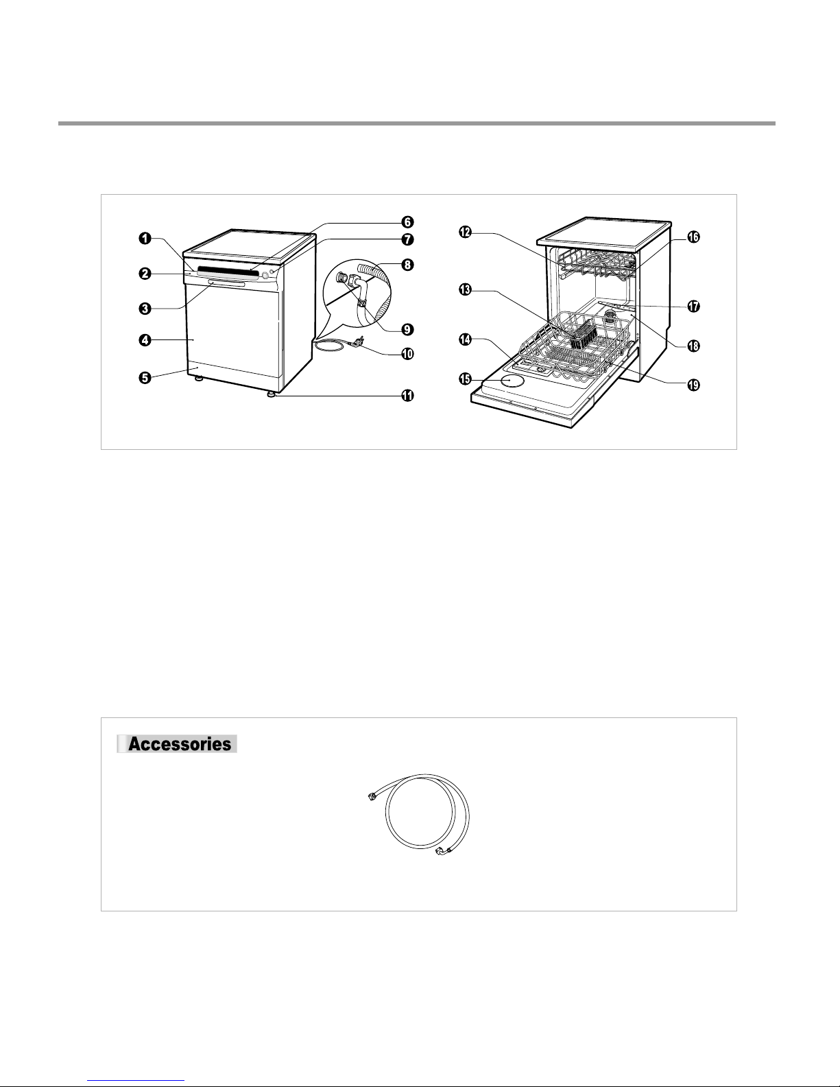
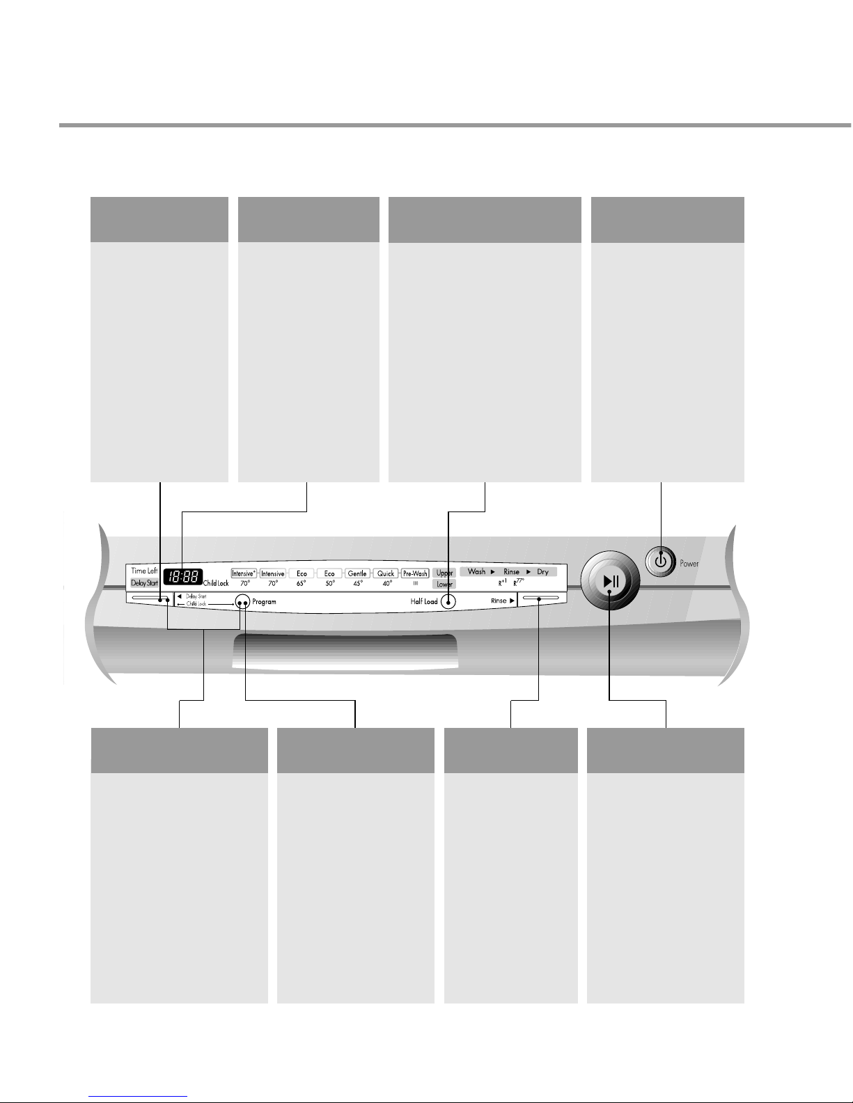
3. PARTS NAME .................................................................................................................. 6
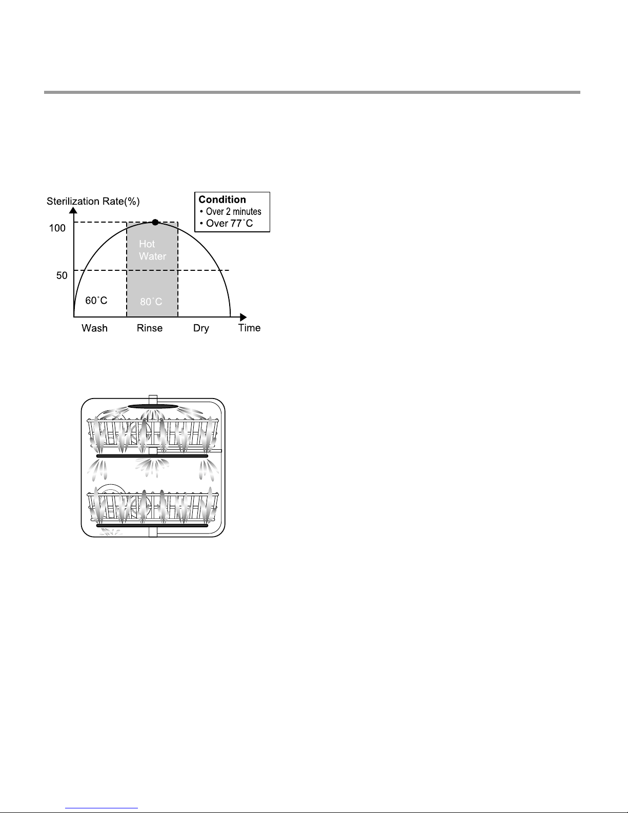
4. FEATURES & TECHNICAL EXPLANATION ................................................................... 7
5. WIRING DIAGRAM...................................................................................................... 10
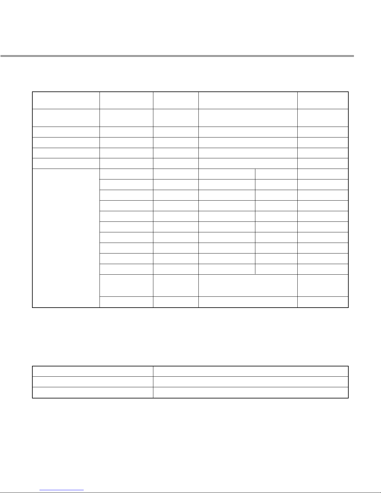
6. PROGRAM CHART (SCHEMATIC DIAGRAM) ............................................................ 11
7. HOW TO DISASSEMBLE ............................................................................................ 12
8. TROUBLE SHOOTING METHODS.............................................................................. 22
A. TROUBLE SHOOTING ACCORDING TO DISPLAYED ERROR MESSAGE.......... 22
B. TROUBLE DIAGNOSES AND REPAIR BY SYMPTOM........................................... 24
9. INSTALLATION INSTRUCTION ................................................................................... 28
10. EXPLODED VIEW .......................................................................................................32
CONTENTS

4
�DISCONNECT POWER CORD BEFORE SERVICING
�RECONNECT ALL GROUNDING DEVICES
IMPORTANT SAFETY NOTICE !
This service information is intended for individuals
possessing adequate backgrounds of electrical,
electronic and mechanical experience.
Any attempt to repair this appliance may result in
personal injury and property damage.
The manufacturer or seller can not be responsible
for the interpretation of this information, nor can it
assume any liability in connection with its use.
CAUTION !

5
2. SPECIFICATION
Rated Voltage / Frequency AC 240V/50Hz
Installation Free Standing
Place Settings 12
Product Dimension(mm) 600(W)×600(D)×850(H)
Product Weight(Kg) 52
Door Color Stainless Steel
Tub Material Stainless Steel
Control Electronic
Rated Power(Watt) 2,210
Heater Power(Watt) 2,100
Programs 7
Upper Rack Sliding Adjustable, Nylon Coating
Lower Rack 50% Fold down, Nylon Coating
Water Consumption(ℓ) 20 (Eco 50)
Power Consumption (kWh/year) 0.7 (Eco 50)
Operating Time (min) 84 (Eco 50)
Fan Dry System Yes
Delay Start Function Yes
Auto Off Power Switch Yes
Process Monitor Yes
Wash Level 5
Operating Water Pressure (Bar) 0.5 ~ 8
ITEM SPECIFICATION

6
3. PARTS NAME
Inlet Hose
1. Vapor vent
2. Control Panel
3. Door Handle
4. Front Cover
5. Lower Cover
6. Process Monitor
7. Power witch
8. Drain Hose
9. Inlet valve A M
10. Power Cord
11. Adjust Leg
12. Upper Rack
13. Cutlery Rack
14. Detergent & Rinse Aid Dispenser
15. Vapor Vent Cover
16. Upper pray Arm
17. Lower pray Arm
18. Filter A M
19. Lower Rack
※The appearance and specifications may be varied without notice according to localities.

7
4. FEATURES & TECHNICAL EXPLANATION
4-1 New Technology Introduction
• During the high temp. Rinse course, water
temperature in an dishwasher reaches 77°C,
considerably higher than the average rinse
temperature in conventional
dishwashers(65°C). This is how Rinse 77°C
can eliminate some bacteria such as
salmonella.
4-1-1. High Temperature Rinsing (Extra Hot function)
• Turbo Spray System is elaborately designed to
achieve a more powerful and efficient wash.
You can see the excellent 3 rotating spray arm
with 5 directional waterjet.
4-1-2. Turbo Spray System

4-2 Display Panel
8
• If you want to delay
the start of selected
program, press this
button before pressing
start button.
• Pressing the delay
time will increase
time by 1 hour.
• The delay start time
can be adjusted from
1 hour to 19 hours.
• In case of small load, use upper
or lower rack only to save
energy.
• With each press, can select
upper or lower rack only.
• In case you don’t select this
button, the machine always
works vario washing, which
operate upper and lower spray
arm alternately.
• For operating, press this
button first for power
on.
• After operating, this
button automatically
switches off for safety
and energy saving.
• If case of irregular surge
disturbances to the
machine, the power may
be automatically turned
off for safety.
DELAY START
BUTTON
• Indication of
remaining time
• elf diagnosis and
error message
display
REMAINING TIME
POWER SWITCH
BUTTON
HALF LOAD
• When power is on,
program is
automatically set to
Eco 65℃.
• If you want to change
the program, press the
button and set the
program you want to.
PROGRAM
• With each press,
rinse+, rinse+ &
77℃sani rinse,
77℃sani rinse is
repeated.
RINSE/
SANI
• Used to lock or unlock
the control buttons to
prevent all the setting
from being changed by a
child.
• For locking/unlocking,
press Delay tart and
Program button
simultaneously.
CHILD LOCK
• With each press, tart
and Pause is repeated
during operation.
• If the machine remains
in Pause mode for 10
minutes, the power is
automatically turned
off.
START/PAUSE
BUTTON

9
4.3 TEST MODE
CHECK PROGRAM(START IN THE STATE OF THE CLOSED DOOR)
※
CHECK MODE
BUTTON
BUTTON OPERATION
Program + Half Load
Program + Rinse
Display Water Supply Frequency
Display Inner Temperature
The number of
pushing button DISPLAY Load and Checking points Door
Micro S/W must be ON to operate HEATER
Half Load + Rinse
+ POWER S/W
Delay Start KEY
Program KEY
Half Load KEY
Rinse KEY
Start/Pause Key
1 TIME
1 TIME
1 TIME
1 TIME
1 TIME
1 TIME
2 TIME
3 TIME
4 TIME
5 TIME
6 TIME
7 TIME
8 TIME
9 TIME
10 TIME
11 TIME
n : 1H ??U100
11 : 11
12 : 22
13 : 33
14 : 44
n : 11
n : 12
n : 13
Frequency
n : 15
n : 16
Temperature
n : 18
n : 19
n : 1A
n : 1b
All LEDs are lighting closed
All LEDs are lighting not concerned
not concerned
not concerned
not concerned
All LEDs are lighting
None Intensive+ closed
closed
not concerned
closed
closed
closed
closed
closed
closed
closed
closed
closed
Washing Motor
Drain Pump
Inlet Valve
Dispenser
Heater(for 10 sec.)
Fan Motor
None
Lower Nozzle
Upper Nozzle
Operate C1 mode(for 1 min.) ??
Drain(for 42 Sec.) ??Supply water
Intensive
Eco 65?
Eco 50?
Gentle
Quick
Pre-wash
Wash
Rinse
Dry
12 TIM Power OFF AUTO OFF

10
5. WIRING DIAGRAM

11
6. PROGRAM CHART(SCHEMATIC DIAGRAM)

12
BEFORE DISASSEMBLING THE DISHWASHER ;
1) Remove the plug from electric outlet to avoid electric shock.
2) Close the Water Tap(faucet).
3) Remove all dishes and items in the dishwasher.
4) Remove the Lower Rack and the Upper Rack.
5) In case of the water softner assembly model, open the water softner cap to flow out the
water to sump and drain to avoid the floor wet.
6) If necessary, remove the inlet hose and drain hose to avoid the hose damages.
7) Prepare some towels to avoid floor wet by the water left in the dishwasher.
7. HOW TO DISASSEMBLE
7-1. FULL DISASSEMBLE
1. Top Table
1) Remove the rear 2 screws.
2) Pull and lift the top table.
2. Low Cover
3. Cabinet-R/L
1) Cabinet-R
①Remove front 4 screws.
②Remove rear 3 screws.
2) Cabinet-L
①Remove front 4 screws.
②Remove rear 3 screws.

13
4. Balance weight
1) Remove side 4 screws.
2) Lift the balance weight.
5. Door Assembly
1) Front Cover
①Open the door.
②Remove 6 screws(stainless).
③Close the door slowly and remove front
cover downwards.
2) Control Panel Assembly
①Open the door.
②Remove 4 screws(stainless).
③Remove wire connection.
Be sure the wiring should not be
changed in reassembling.
④Remove 3 screws for Latch assembly.
⑤Remove 5 screws for Controller.

14
3) Fan
①Open the door.
②Remove the air duct.
③Remove the wire connections.
④Remove the outer cover by removing 1
screw.
⑤Remove 2 fixing screws inside and turn
the Inner Cover counterclockwise.
4) Detergent Dispenser
①Close the door.
②Remove the wire connections.
③Remove 6 screws with brackets.
Door Liner Assembly
Hinge supporter
②
①
5) Door Spring (Right & Left)
①Push the Spring upwards and take it off
from the Frame.
Be careful not to be injured by the sharp
edge of Tub.
②Take the Hinge Link off from the Hinge.
6) Door Liner
①Open the door.
②Pull the Door Liner and take it off from
the Hinge Supporter.

15
6. Base spacer
①Remove 4 screws.
②Lift the front side of dishwasher and pull
the base spacer forward.
7. Tub assembly
1) Nozzle
①Pull up the nozzle.
3) Nozzle Holder
①Disconnect the water guide
②Remove 4screws and lift it up
Main filter
Inner filter
Middle filter
Micro filter
2) Filter Assembly
①Turn inner filter counterclockwise and lift
inner filter and middle filter.
You can disassemble inner filter and
middle filter by pulling opposite direction.
②Lift up main filter.
③Lift up micro filter.

16
4) Tub
①Turn the air guide nut counter clockwise.
(Special tool might be needed.)
Be careful the rubber packing of air
guide assembly should not be lost.
②Remove 4 screws for sump holder .
③Remove side 8 screws.
④Remove 2 Earth screw of right side.
⑤Lift tub assembly upward.
Be careful not to be injured or scratch
floor by the sharp edge of tub.
8. Air Guide Assembly
①Disconnect the wiring connection.
②Remove 3 hoses assembly.
Be careful the o ring should not be lost.
9. C-Base Assembly
1) Remove the screw which tighten washing
motor and base.
2) Lift them upward.
Be careful not to wet the floor by the
water left in the sump.
3) Detach the washing motor and heater
assembly by pulling opposite direction
to sump.
4) Remove the 3 screw for drain motor.

17
10. C-Base Assembly
1) synchronous motor
①Remove the 2 screws.
②Lift the cam upward.
※Be careful not to install upside down.
(part number on the cam should face the
motor.)
2) Vario valve
①Remove 4 screws and lift the cover
upward.
②Lift the vario valve upward.
3) Capacitor
①Remove 1 screw.
4) Power cord assembly
①Turn the power cord assembly 90º and
take it off.

18
5) Inlet Valve
①Remove 2 screws.
6) Drain Hose
①Press the rear side hook.
②Pull the holder forward.
③Pull the holder upward.
③
②

19
1. Top Plate
�See 7 1. 1. (Page 12)
2. Low Cover
�See 7 1. 2. (Page 12)
3. Cabinet-R/L
�See 7 1. 3. (Page 12)
4. Air Guide
①Disconnect 3 hoses assembly.
※You need not to unscrew the air guide
nut.
5. Put the Dishwasher upside down.
7-2. DISASSEMBLE C-BASE ASSEMBLY
Be careful not to be injured by the sharp edge of tub.

20
7. Disconnect the connecting points
between tub and base
1) Disconnect of powercord assembly.
2) Disconnect wire from the capacitor.
6. Remove the side screws
1) Remove side 8 screws.
2) Remove 2 Earth screws of right side.
3) Remove 1 motor bracket screw.
4) Lift base upward slightly.
(You can’t lift up base perfectly because of
some parts connecting to base.)
This manual suits for next models
1
Table of contents
Other LG Dishwasher manuals

LG
LG GD-E701NW User manual

LG
LG LD-2130WH User manual

LG
LG LDF5545BD/00 User manual

LG
LG LD-2166WH User manual

LG
LG LDF9810ST - Fully Integrated 6 Wash Cycles... User manual

LG
LG LDFN343 Series User manual

LG
LG D1441 Series User manual

LG
LG KD-C705NW User manual

LG
LG LDF7932 User manual

LG
LG LDT9965BD User manual

LG
LG LD-1415M1 User manual

LG
LG D1450WLFB1 User manual

LG
LG LDP567 SERIES User manual

LG
LG LDS4821BB - 24in Full Console Dishwasher User manual

LG
LG LDTS555 Series User manual

LG
LG LDS5540ST User manual

LG
LG STEAMDISHWASHER LDF7932ST User manual

LG
LG LDF8812ST User manual

LG
LG LDS5560ST Assembly instructions

LG
LG LDP681 Series User manual