INSTALLATION INSTRUCTIONS
IINNSSTTAALLLLAATTIIOONNIINNSSTTRRUUCCTTIIOONNSS
9
Step 8
Step 9
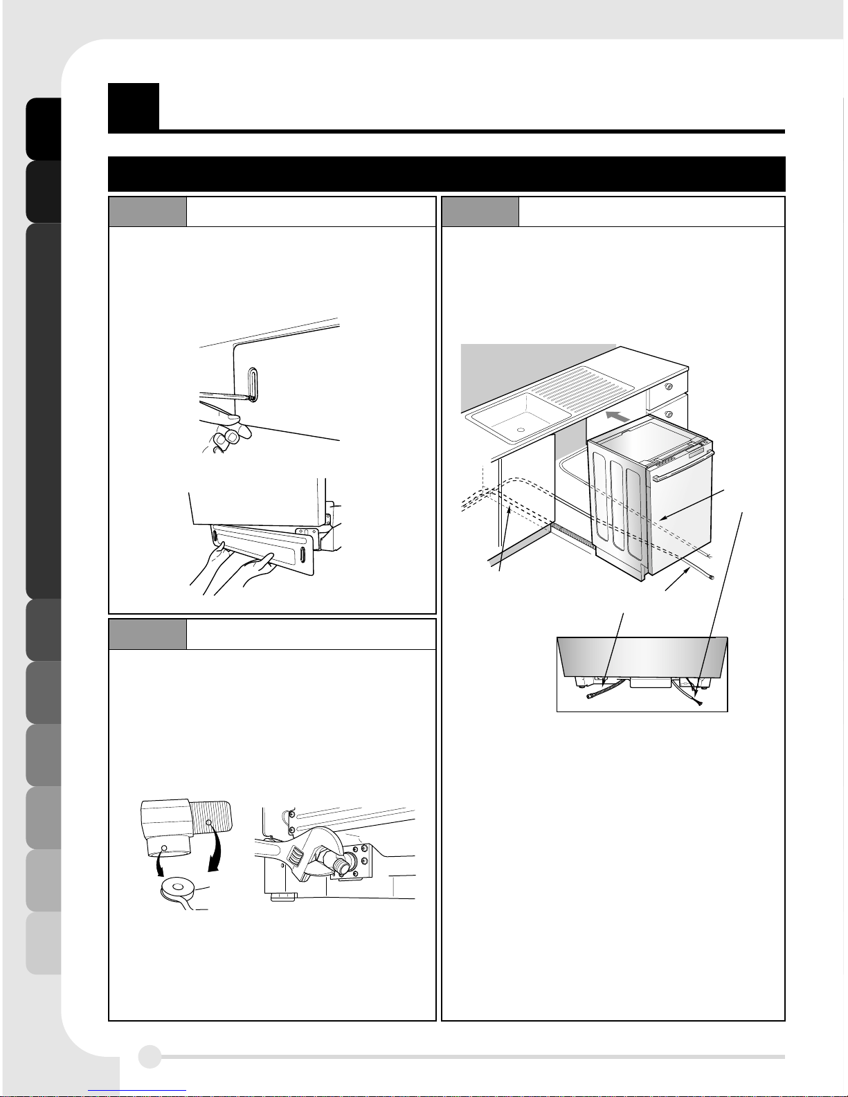
LEVEL DISHWASHER
SECURE DISHWASHER TO THE COUNTERTOP
Secure dishwasher to the countertop or the cabinet.
When the countertop is made of wood or will not be damaged by drilling, use Step 9-1.
When the countertop is made of granite, marble or others which could be damaged by
drilling, Use Step 9-2.
Check that the dishwasher is level. (Fig. A)
Attach level on top front opening of tub from side to side
Check that the dishwasher is plumb. (Fig. B)
Attach level on front side of cabinet
Check that gap between door and tub is equal on both side’s
(L, R) (Fig. C)
If the dishwasher is not level or both side gap is not equal,
adjust four leveling feet up or down until dishwasher is level
and both side gap is equal. (Fig. D)
1. Remove the Plastic Bushing
2. Drive Wood Screw through the hole
(Install Bracket is located between tub
and side cabinet by manufacturer)
3. Reinstall Plastic Bushings.
STEP 9-1
Fig. D
STEP 9-2
Important Tip
1) Cover the Filter Hole by towels to prevent screws from falling down to pump.
2) Use a Magnetic Drive to prevent screws from falling down into the gap in step9-2.
Plastic Bushing
Wood Screw
1. Locate the installation brackets in the slot
2. Bend the brackets to secure them to the
dishwasher tub
3. Secure the dishwasher to the countertop
with the screws provided through the
holes in the bracket
These installation instructions are intended for use by Qualified lnstallers.


F(B,U) User manual")