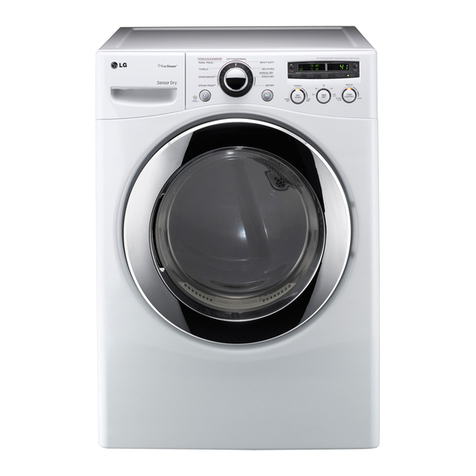
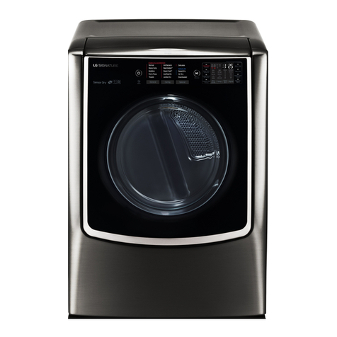
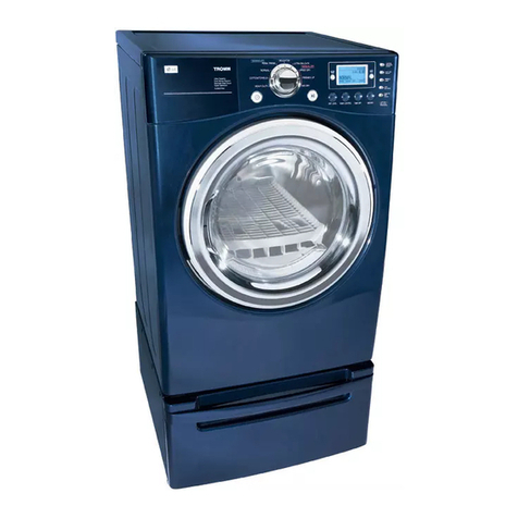
LG GDL1329CGS3 User manual

ELECTRIC & GAS DRYER
SERVICE MANUAL
CAUTION
READ THIS MANUAL CAREFULLY IN ORDER TO PROPERLY DIAGNOSE PROBLEMS
AND TO SAFELY PROVIDE QUALITY SERVICE ON THESE DRYERS.
MODEL : GDL1329CGS3/GDL1329CES3
GDL1329CGD3/GDL1329CED3
GDL1329CGW3/GDL1329CEW3
GDL1329QGS3/GDL1329QES3
GDL1329QGD3/GDL1329QED3
GDL1329QGW3/GDL1329QEW3
C
E
R
T
I
F
I
E
D
D
E
S
I
G
N

2
2
To avoid injury to persons disconnect power before se rvicing this product. If electrical power is required
for diagnosis or test purposes, disconnect the power immediately after performing the necessary checks.
Do not try to light a match, or cigarette, or turn on
any gas or electrical appliance.
Do not touch any electrical switches. Do not use any
phone in your building.
Clear the room, building or area of all occupants.
Immediately call your gas supplier from a neighborís
phone. Follow the gas supplierís instructions
carefully.
If you cannot reach your gas supplier, call the fire
department.

3
CONTENTS
1.IMPORTANT SAFETY INSTRUCTIONS ............................................................................. 4
2.SPECIFICATIONS ............................................................................................................... 9
3.FEATURES AND BENEFITS ............................................................................................. 11
4.INITIAL STEPS FOR INSTALLING YOUR DRYER............................................................ 13
5.STACK MACHINE INSTALLATION INSTRUCTIONS ....................................................... 19
6.ELECTRICAL REQUIREMENTS FOR ELECTRIC DRYERS ............................................ 29
7.ELECTRICAL REQUIREMENTS FOR GAS DRYERS ...................................................... 34
8.GAS REQUIREMENTS AND INSTRUCTIONS ................................................................. 35
9.EXHAUST REQUIREMENTS AND MAINTENANCE ......................................................... 36
10. DRYER CYCLE PROCESS ............................................................................................ 40
11. COMPONENT TESTING INFORMATION ...................................................................... 41
12. MOTOR DIAGRAM AND SCHEMATIC............................................................................ 44
13. CONTROL LAYOUT ........................................................................................................ 45
14. WIRING DIAGRAM .......................................................................................................... 46
15. DIAGNOSTIC TEST ......................................................................................................... 47
15-1. TEST 1 120VAC ELECTRICAL SUPPLY ............................................................ 48
15-2. TEST 2 THERMISTOR TEST ............................................................................... 51
15-3. TEST 3 MOTOR TEST ......................................................................................... 52
15-4. TEST 4 MOISTURE SENSOR .............................................................................. 53
15-5. TEST 5 DOOR SWITCH TEST ............................................................................. 54
15-6. TEST 6 HEATER SWITCH TEST - ELECTRIC MODEL ...................................... 55
15-7. TEST 7 GAS VALVE TEST - GAS MODEL ......................................................... 56
16. ERROR MODE ................................................................................................................ 57
17. SMART FUNCTIONS........................................................................................................ 58
18. CHANGE GAS SETTING (NATURAL GAS, PROPANE GAS) ...................................... 61
19. DISASSEMBLY INSTRUCTIONS ................................................................................... 63
20. EXPLODED VIEW ........................................................................................................... 71
20-1-1. Control Panel & Plate Assembly - Coin Type....................................................... 71
20-1-2. Control Panel & Plate Assembly - Card Type ...................................................... 72
20-2-1. Cabinet & Door Assembly - Electric Stack Upper Type ....................................... 73
20-2-2. Cabinet & Door Assembly - Electric Stack Lower Type ....................................... 74
20-2-3. Cabinet & Door Assembly - Gas Stack Upper Type ............................................ 75
20-2-4. Cabinet & Door Assembly - Gas Stack Lower Type ............................................ 76
20-3-1. Drum & Motor Assembly: Electric Type ............................................................... 77
19-3-2. Drum & Motor Assembly: Gas Type..................................................................... 78

4
1IMPORTANT SAFETY INSTRUCTIONS
•Read all instructions before using the dryer.
•Before use, the dryer must be properly installed
as described in this manual.
•Do not place items exposed to cooking oils in
your dryer. Items contaminated with cooking oils
may contribute to a chemical reaction that could
cause a load to catch fire.
•Do not dry articles that have been previously
cleaned in, washed in, soaked in, or spotted with
gasoline, dry-cleaning solvents, or other
flammable or explosive substances as they give
off vapors that could ignite or explode.
•Do not reach into the dryer if the drum or any
other part is moving.
•Do not repair or replace any part of the dryer or
attempt any servicing unless specifically
recommended in this Use and Care Guide or in
published user-repair instructions that you
understand and have the skills to carry out.
•Do not tamper with controls.
•Before the dryer is removed from service or
discarded, remove the door to the drying
compartment.
•Do not allow children to play on or in the dryer.
Close supervision of children is necessary when
the dryer is used near children.
•Do not use fabric softeners or products to
eliminate static unless recommended by the
manufacturer of the fabric softener or product.
•Do not use heat to dry articles containing foam
rubber or similarly textured rubber-like materials.
•Keep area around the exhaust opening and
adjacent surrounding areas free from the
accumulation of lint, dust, and dirt.
•The interior of the dryer and exhaust vent should
be cleaned periodically by qualified service
personnel.
•Do not install or store the dryer where it will be
exposed to the weather.
•Always check the inside of the dryer for foreign
objects.
•Clean lint screen before or after each load.
Your Safety and the safety of others is very important.
BASIC SAFETY PRECAUTIONS
You can be killed or seriously injured if you don’t immediately follow instructions.
You can be killed or seriously injured if you don’t follow instructions.
All safety messages will tell you what the potential hazard is, tell you how to reduce the
chance of injury, and tell you what can happen if the instructions are not followed.
We have provided many important safety messages in this manual and on your appliance.
Always read and obey all safety messages.
This is the safety alert symbol.
This symbol alerts you to potential hazards that can kill or hurt you and others.
All safety messages will follow the safety alert symbol and either the word DANGER or WARNING.
These words mean:
READ ALL INSTRUCTIONS BEFORE USE
WARNING:
To reduce the risk of fire, electric shock, or injury to persons when using this
appliance, follow basic precautions, including the following:
For your safety, the information in this manual must be followed to minimize
the risk of fire or explosion, electric shock, or to prevent property damage, injury to person, or death.
WARNING
DANGER:
WARNING:

5
READ ALL INSTRUCTIONS BEFORE USE
CALIFORNIA SAFE DRINKING WATER AND TOXIC ENFORCEMENT ACT
This act requires the governor of California to publish a list of substances known to the state to
cause cancer, birth defects, or other reproductive harm and requires businesses to warn
customers of potential exposure to such substances.
Gas appliances can cause minor exposure to four of these substances, namely benzene, carbon
monoxide, formaldehyde, and soot, caused primarily by the incomplete combustion of natural gas
or LP fuels.
Properly adjusted dryers will minimize incomplete combustion. Exposure to these substances can
be minimized further by properly venting the dryer to the outdoors.
For your safety, the information in this manual must be followed to minimize the risk of fire
or explosion, electric shock, or to prevent property damage, injury to person, or death.
WARNING
FIRE OF EXPLOSION HAZARD
Failure to follow safety warnings exactly could result in
serious injuly, death or property damage.
- Do not store or use gasoline or other flammable vapors
and liquids in the vicinity of this or any other appliance.
- WHAT TO DO IF YOU SMELL GAS
ヲUDo not try to light any appliance.
ヲUDo not touch any electrical switch; do not use any
phone in your building.
ヲUClear the room, building or area of all occupants.
ヲUImmediately call your gas supplier from a neighborヲs
phone. Follow the gas supplierヲs instructions.
ヲU
If you cannot reach your gas supplier, call the fire
department.
- Installation and service must be performed by a
qualified installer, service agency or the gas supplier.
WARNING

6
To reduce the risk of fire, electric shock, or injury to persons when using
this appliance, follow basic precautions, including the following:
WARNING
READ ALL INSTRUCTIONS BEFORE USE
For your safety, the information in this manual must be followed to minimize the risk of
fire or explosion, electric shock, or to prevent property damage, injury to person, or death.
GROUNDING INSTRUCTIONS
This appliance must be grounded. In the event of
malfunction or breakdown, grounding will reduce
the risk of electric shock by providing a path of
least resistance for electric current. This appliance
must be equipped with a cord having an
equipment-grounding conductor and a grounding
plug. The plug must be plugged into an appropriate
outlet that is properly installed and grounded in
accordance with all local codes and ordinances.
person if you are in doubt as to whether the
appliance is properly grounded.
Do not modify the plug provided with the appliance.
If it will not fit the outlet, have a proper outlet
installed by a qualified electrician.
This appliance must be connected to a grounded
metal, permanent wiring system or an equipment-
grounding conductor must be run with the circuit
conductors and connected to the equipment-
grounding terminal or lead on the appliance.
Electric shock can result if the dryer is not properly
grounded.
SAFETY INSTRUCTIONS FOR INSTALLATION
•Properly ground dryer to conform with all
governing codes and ordinances. Follow details
in the installation instructions. Electric shock can
result if the dryer is not properly grounded.
•Before use, the dryer must be properly
installed as described in this manual.
Electric shock can result if the dryer is not
properly grounded.
•Install and store the dryer where it will not be
exposed to temperatures below freezing or
exposed to the weather.
•All repairs and servicing must be performed by
an authorized servicer unless specifically
recommended in this Owner’s Guide. Use only
authorized factory parts. Failure to follow this
warning can cause serious injury, fire, electricl
shock, or death.
•To reduce the risk of electric shock, do not
install the dryer in humid spaces. Failure to
follow this warning can cause serious injury, fire,
electric shock, or death.
•Connect to a properly rated, protected, and
sized power circuit to avoid electrical overload.
Improper power circuit can melt, creating electric
shock and/or fire hazard.
•Remove all packing items and dispose of all
shipping materials properly. Failure to do so
can result in death, explosion, fire, or burns.
•Place dryer at least 18 in. above the floor for a
garage installation. Failure to do so can result in
death, explosion, fire, or burns.
•Keep all packaging from children. Packaging
material can be dangerous for children. There is a
risk of suffocation.
WARNING
ヲ Improper connection of
the equipment-grounding
conductor can result in a risk of electric shock.
Check with a qualified electrician or service
WARNING
7
READ ALL INSTRUCTIONS BEFORE USE
For your safety, the information in this manual must be followed to minimize the risk of fire
or explosion, electric shock, or to prevent property damage, injury to person, or death.
Exhaust/Ducting:
•Gas dryers MUST be exhausted to the outside.
Failure to follow these instructions can result in fire or
death.
•The dryer exhaust system must be exhausted to
the outside of the dwelling. If the dryer is not
exhausted outdoors, some fine lint and large
amounts of moisture will be expelled into the
laundry area. An accumulation of lint in any area of
the home can create a health and fire hazard.
•Use only rigid metal or flexible metal 4-in.
diameter ductwork inside the dryer cabinet or for
exhausting to the outside. Use of plastic or other
combustible ductwork can cause a fire. Punctured
ductwork can cause a fire if it collapses or becomes
otherwise restricted in use or during installation.
•Ductwork is not provided with the dryer, and you
should obtain the necessary ductwork locally.
The end cap should have hinged dampers to
prevent backdraft when the dryer is not in use.
Failure to follow these instructions can result in fire or
death.
•The exhaust duct must be 4 in. (10 cm) in
diameter with no obstructions. The exhaust duct
should be kept as short as possible. Make sure to
clean any old ducts before installing your new
dryer. Failure to follow these instructions can result in
fire or death.
•Rigid or semi rigid metal ducting is
recommended for use between the dryer and the
wall. In special installations when it is impossible
to make a connection with the above
recommendations, a UL-listed flexible metal
transition duct may be used between the dryer
and wall connection only. The use of this ducting
will affect drying time. Failure to follow these
instructions can result in fire or death.
•Do not use sheet metal screws or other fasteners
which extend into the duct that could catch lint
and reduce the efficiency of the exhaust system.
Secure all joints with duct tape. For complete
details, follow the Installation Instructions. Failure
to follow these instructions can result in fire or death.
¥ Keep the area underneath and around your
appliances free of combustible materials such as
lint, paper, rags, chemicals, etc. Failure to do so
can result in fire.
WARNING
Fire Hazard
Failure to follow safety warning exactly could result in
serious injuly, death or property damage.
Do not install a booster fan in the exhaust duct.
Install all clothes dryers in accordance with the
installation instructions of the manufacturer of the dryer.
WARNING
SAFETY INSTRUCTIONS FOR INSTALLATION

8
READ ALL INSTRUCTIONS BEFORE USE
For your safety, the information in this manual must be followed to minimize the risk of
fire or explosion, electric shock, or to prevent property damage, injury to person, or death.
WARNING
SAFETY INSTRUCTIONS FOR CONNECTING ELECTRICITY
To reduce the risk of fire, electric shock, or injury to persons when using this
appliance, follow basic precautions, including the following:
WARNING:
•Do not, under any circumstances, cut or remove
the ground prong from the power cord. To prevent
injury to person or damage to the dryer, the electrical
power cord must be plugged into a properly grounded
outlet.
•For personal safety, this dryer must be properly
grounded. Failure to do so can result in electric shock
or injury.
•Refer to the installation instructions in this manual
for specific electrical requirements for your model.
Failure to follow these instructions can create an
electric shock hazard and/or a fire hazard.
•This dryer must be plugged into a properly
grounded outlet. Electric shock can result if the
dryer is not properly grounded. Have the wall
outlet and circuit checked by a qualified electrician
to make sure the outlet is properly grounded.
Failure to follow these instructions can create an
electric shock hazard and/or a fire hazard.
•The dryer should always be plugged into its own
individual electrical outlet which has a voltage
rating that matches the rating plate. This provides
the best performance and also prevents overloading
house wiring circuits which could cause a fire hazard
from overheated wires.
•Never unplug your dryer by pulling on the power
cord. Always grip plug firmly and pull straight out
from the outlet. The power cord can be damaged,
resulting in a risk of fire and electric shock.
•Repair or replace immediately all power cords that
have become frayed or otherwise damaged. Do not
use a cord that shows cracks or abrasion damage
along its length or at either end. The power cord can
melt, creating electric shock and/or fire hazard.
•When installing or moving the dryer, be careful not
to pinch, crush, or damage the power cord. This will
prevent injury and prevent damage to the dryer from
fire and electric shock.
•To reduce the risk of injury to person, adhere to all
industry recommended safety procedures
including the use of long sleeved gloves and safety
glasses. Failure to follow all of the safety warnings in
this manual could result in property damage, injury to
person or death.
•Connect the power cord to the terminal block. Each
colored wire should be connected to same color
screw. Wire color indicated on manual is
connected to the same color screw in block. Failure
to follow these instructions may result in a short or
overload.
WARNING
ELECTRIC SHOCK HAZARD
Failure to follow safety warnings could result in serious injuly or death.
This dryer is equipped with a three-prong grounding plug to protection against shock hazard and
should be plugged directly into a properly grounded three-prong receptacle. Do not cut or remove the
grounding prong from this plug.
SAVE THESE INSTRUCTIONS

9
•Type : Electric and Gas Dryer
•Rating : Please refer to the rating label regarding detailed information.
•Single dryer Size : 686mm(W) x 764mm(D) x 983mm(H)
27in(W) X 30in(D) X 38.7in(H)
•Stack dryer Size : 686mm(W) x 764mm(D) x 1954mm(H)
27in(W) X 30in(D) X 76.9in(H)
•Capacity : IEC 7.3 cu.ft. (22.5 lb)
•Weight : 131 Ibs (59.4 kg)
•Specifications are subject to change by manufacturer.
2SPECIFICATIONS

10
TYPE
POWER SUPPLY
CONTROL TYPE
DRUM CAPACITY
Weight (lbs.) - Net/Gross
No. of Programs
Audible End of Cycle Beeper
Time dry
Reversible Door
Drum
Product (WxHxD)
Packing (WxHxD)
120/240V, 24 Amps
White, Silver
Painted
Stainless Deco
Chrom
White, Silver
420W (4.5V)
5400W (22.5A) -
13W (110mA) x 2-
Electronic
IEC 7.3 cu.ft.
126/144
4
Available
Available
Available
Alcosta
686mm(W) x 764mm(D) x 983mm(H)
29 7/10(W) x 44 7/10(H) x 31 2/5(D) (Inch)
Color
MATERIAL
& FINISH
ELECTRICITY
CONSUMPTION
Top Plate
Door Trim
Door Frame
C/Panel Color
MOTOR
HEATER
GAS VALVE
Electric
120V, 7 Amps
AC 120V
AC 240V (ELECTRIC MODEL)
Gas (LNG)
REMARK
ITEM
GDL1329CES3
GDL1329CED3
GDL1329CEW3
GDL1329QES3
GDL1329QED3
GDL1329QEW3
GDL1329CGS3
GDL1329CGD3
GDL1329CGW3
GDL1329QGS3
GDL1329QGD3
GDL1329QGW3

11
3FEATURES AND BENEFITS
Side by side (GDL1329CES3, GDL1329CGS3)
Stack upper (GDL1329CEW3, GDL1329CGW3)
Stack lower (GDL1329CED3, GDL1329CGD3)
1 24
3
1 24
3

12
- Side by side (GDL1329QES3, GDL1329QGS3)
- Stack upper (GDL1329QEW3, GDL1329QGW3)
- Stack lower (GDL1329QED3, GDL1329QGD3)
1 24
3
1 24
3
1 24
3

13
4
INITIAL STEPS FOR INSTALLING YOUR DRYER

14

15

16

17

18
The following instructions are applicable to
installations of the dryer in a manufactured or
mobile home. Any installation in a
manufactured or mobile home must comply
with the Manufactured Home Construction and
Safety Standards Title 24 CFR, Part 32-80 or
Standard CAN/CSA0Z240 MH and local codes
and ordinances. If you are uncertain whether
your proposed installation will comply with
these standards, please contact a service and
installation professional for assistance.
The following instructions apply to any
installation of the dryer in a manufactured or
mobile home:
1) The gas dryer must be permanently
attached to the floor.
2) The electrical connection for an electric
dryer must be a 4-wire connection. More
detailed information concerning the electrical
connection is provided at the manual section
entitled Electrical Requirements for Electric
Dryer
3) To reduce the risk of combustion and fire,
the dryer must be vented to the outside.
4) Electric dryers may be vented to the outside
using the back, left, right, or bottom panel.
5) Gas dryers may be vented to the outside
using the back, left, or bottom panel. Gas
dryer may not be vented to the outside using
the right side panel because of the burner
housing.
6) The dryer exhaust duct must be affixed
securely to the manufactured or mobile
home structure, and the exhaust duct must
be made of a material that will resist fire and
combustion, and it is recommended that you
use a rigid or flexible metal pipe.
7) DO NOT connect the exhaust duct with any
other duct, vent, chimney, or other exhaust
duct.
8) Make sure the dryer has adequate access to
outside fresh air to ensure proper operation.
The opening for outside fresh air must be at
least 25 in2(163 cm2).
9) It is important that the clearance of the duct
from any combustible construction be at
least 2 inches (5 cm), and, when venting the
dryer to the outdoors, the dryer can be
installed with a clearance of 1 inch at the
sides and back of the dryer.
10) Please be aware that venting materials are
not supplied with the dryer. You should
obtain the venting materials necessary for
proper installation.
WARNING
Do not connect exhaust ducts with
metal screws or fasteners that extend
into the duct.
WARNING
Do not vent the exhaust duct under the
manufactured or mobile home.
STEP 9
Additional Instructions
for Installation of Your
Dryer in a Manufactured
or Mobile Home.

19
5
STACK MACHINE INSTALLATION INSTRUCTIONS
How to connect the housing
The dryer has a connector for both a coin collector and a card reader. Use the one you need and tuck
the other one away safely.
1-1
1-2
1-3
1
Coin/Card housing
Single Coin & Card
CARD TYPE (Single)
WARNING
•Disconnect power before service.
•Failure to follow these instructions can result
in death or electric shock.
When power on the machine at
first time without connecting
card reader or coin housing
,display will show LqC1
COIN TYPE
Coin housing
Card reader
housing
The Coin drop assembly operates on DC12V in dryer.
The Card reader assembly operates on DC12V in dryer.
Note

20
2
SUITABLE MODEL FOR STACKING
3
STACKING KIT
Stack type
Model Name
Stack type
GDL1329CEW3, GDL1329CGW3
GDL1329QEW3, GDL1329QGW3
Lower Dryer
GDL1329CED3, GDL1329CGD3
GDL1329QED3, GDL1329QGD3
Lower Washer
GCWL1069CD5
GCWL1069QD5
- STACKING KIT is provided in the upper dryer.
- STACKING KIT includes the stacking bracket(1), sec unity bracket(3), bolt(1), screw(9).
1) Stacking bracket 2) bolt 3) Screw 4) security bracket
2) Sliding pad 3) Screw
- SLDING KIT includes the silde bracket(2), sliding pad(4), screw(18).
1) Sliding Blacket
This manual suits for next models
11
Table of contents
Other LG Dryer manuals
Popular Dryer manuals by other brands

Beko
Beko DVTC 60 W Installation & operating instructions and drying guidance

St George
St George LEG37A*F4350 Use and care guide

Dexter Laundry
Dexter Laundry T-30 Operators manual installation & operation instructions

iOCEAN
iOCEAN OC-GYJ8022 user manual

Bosch
Bosch Nexxt 100 Series Operating, care and installation instructions

Tricity Bendix
Tricity Bendix Deluxe TM545 Operating & installation instructions