LG GSA-4163B User manual

Super Multi DVDDrive
SERVICE MANUAL
MODEL: GSA-4163B
P/NO : 3828HS1047F
December 2004
Printed in Korea
MODEL : GSA-4163B

TABLE OF CONTENTS
INTRODUCTION .......................................................................................................................................................................3
FEATURES............................................................................................................................................................................3~4
SPECIFICATIONS.................................................................................................................................................................5~8
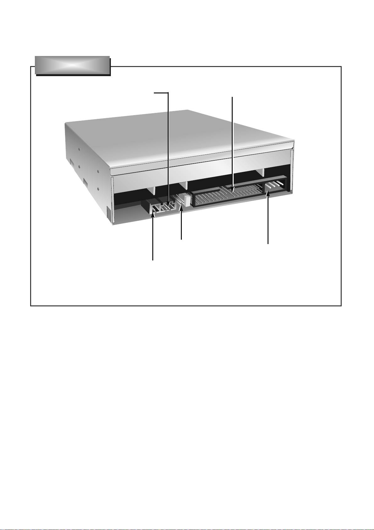
LOCATION OF CUSTOMER CONTROLS .........................................................................................................................9~10
DISASSEMBLY.................................................................................................................................................................11~12
1. CABINET and CIRCUIT BOARD DISASSEMBLY..........................................................................................................11
1-1. Bottom Chassis..........................................................................................................................................................11
1-2. Front Bezel Assy........................................................................................................................................................11
1-3. Cabinet and Main Circuit Board.................................................................................................................................11
2. MECHANISM ASSY DISASSEMBLY..............................................................................................................................11
2-1. Pick-up Unit................................................................................................................................................................11
2-2. Pick-up ......................................................................................................................................................................12
EXPLODED VIEW.............................................................................................................................................................13~14
MECHANICAL REPLACEMENT PARTS LIST ......................................................................................................................15
GLOSSARY.............................................................................................................................................................................16
THE DIFFERENCES OF CD-R/CD-RW DISCS AND GENERAL CD-ROM.....................................................................17~23
1. Recording Layer..............................................................................................................................................................17
2. Disc Specification............................................................................................................................................................17
3. Disc Materials..................................................................................................................................................................18
4. Reading Process of Optical Disc.....................................................................................................................................19
5. Writing Process of CD-R Disc .........................................................................................................................................20
6. Writing Process of CD-RW Disc......................................................................................................................................20
7. Organization of the PCA, PMA and Lead-in Area ...........................................................................................................21
8. Function of PCA and PMA area ......................................................................................................................................22
9. OPC and ROPC ..............................................................................................................................................................22
10. Writing Process of DISC................................................................................................................................................23
THE DIFFERENCES OF DVD-R/RW, DVD+R/RW DISCS AND DVDD-ROM.................................................................24~32
1. Recording Layer..............................................................................................................................................................24
2. Disc Specification............................................................................................................................................................25
3. Disc Materials..................................................................................................................................................................25
4. Writing Pulse Waveform of DVD+R.................................................................................................................................28
5. Writing Pulse Waveform DVD+RW.................................................................................................................................30
6. Organization of Inner Drive Area, Outer Drive Area, Lead-in Zone and Lead-out Zone .................................................31
DVD & CD DATA PROCESSING......................................................................................................................................33~36
1. Data Processing Flow......................................................................................................................................................33
2. Copy Protection and Regional Code Management Block ...............................................................................................34
3. About Prevention the DVD-ROm from to be copy...........................................................................................................35
4. About the DVD-ROM Regional Code..............................................................................................................................36
INTERNAL STRUCTURE OF THE PICK-UP....................................................................................................................37~39
1. Block Diagram of the Pick-up(HOP-7532TS)..................................................................................................................37
2. Pick up Pin Assignment...................................................................................................................................................38
3. Signal detection of the P/U..............................................................................................................................................39
DESCRIPTION OF CIRCUIT.............................................................................................................................................40~47
1. ALPC Circuit....................................................................................................................................................................40
2. Focus Circuit....................................................................................................................................................................42
3. Tracking & Sled Circuit....................................................................................................................................................43
4. Spindle Circuit .................................................................................................................................................................46
MAJOR IC INTERNAL BLOCK DIAGRAM AND PIN DESCRIPTION.............................................................................48~68
TROUBLESHOOTING GUIDE..........................................................................................................................................69~86
BLOCK DIAGRAM..................................................................................................................................................................88
PRINTED CIRCUIT BOARD DIAGRAM...........................................................................................................................89~92
ELECTRICAL REPLACEMENT PARTS LIST........................................................................................................................93
CAUTION - INVISIBLE LASER RADIATION WHEN OPEN AVOID EXPOSURE TO BEAM.

3
INTRODUCTION
FEATURES
1 General
1) Enhanced IDE (ATAPI) interface.
2) Internal Half-height Drive.
3) CD-R/RW, DVD-R/RW/RAM/+R/+R DL(Double Layer)/+RW read and write compatible CD Family and
DVD-ROM read compatible.
4) Buffer Under-run prevention function embedded.
5) 2MB buffer memory.
6) Power loading and power eject of a disc. Bare media loading.
7) MTBF : 100,000 POH
8) Vertical and Horizontal installable.
2. Supported disc formats
1) Reads data in each DVD-ROM, DVD-R(Ver. 2.0 for Authoring) and DVD-RAM(Ver.1.0)
2) Reads and writes in each DVD-R(Ver. 2.0 for General), DVD-RW, DVD-RAM(Ver.2.2), DVD+R, DVD+R
DL(Double Layer) and DVD+RW
3) Reads data in each CD-ROM, CD-ROM XA, CD-I, Video CD, CD-Extra and CD-Text
4) Reads data in Photo CD (Single and Multi session)
5) Reads standard CD-DA
6) Support to read Super Audio CD(Compatible layer in Hybrid type)
7) Reads and writes CD-R discs conforming to “Orange Book Part 2”
8) Reads and writes CD-RW discs conforming to “Orange Book Part 3”
9) Reads DVD-RAM with CPRM and DVD-RW with CPRM
This service manual provides a variety of service
information.
It contains the mechanical structure of the Super
Multi DVD Drive and the electronic circuits in
schematic form. This Super Multi DVD Drive was
manufactured and assembled under our strict quality
control standards and meets or exceeds industry
specifications and standards.
This Super Multi DVD drive is an internal drive unit
designed for use with IBM PC, HP Vectra, or
compatible computer. It can write as much as 700
Mbytes of digital data into CD-R/RW disc, and can
read as much as 700 Mbytes of digital data stored in
a CD-ROM/R/RW disc.
It can write as much as 4.7Gbytes of digital data into
DVD-R/RW/RAM/+R/+RW disc, and can read as
much as 4.7Gbytes of digital data stored in a
DVD-ROM/R/RW/RAM/+R/+RW disc.
It can write as much as 8.5Gbytes of digital data into
DVD+R DL disc, and can read as much as
8.5Gbytes of digital data stored in a DVD-ROM
DL/+R DL disc.
This Super Multi DVD Drive can easily meet the
upcoming MPC level 3 specification, and its
Enhanced Intelligent Device Electronics (E-IDE) and
ATAPI interface allows Plug and play integration in
the majority of today’s PCs without the need of an
additional interface card.

3. Supported write method
1) DVD-R:..................Disc at Once and Incremental Recording
2) DVD-RW:...............Disc at Once, Incremental Recording and Restricted Overwrite
3) DVD-RAM:.............Random Write
4) DVD+R:.................Sequential Recording
5) DVD+R DL: ...........Sequential Recording
6) DVD+RW:..............Random Write
7) CD-R/RW: .............Disc at Once, Session at Once, Track at Once and Packet Write
4. Performance
1) Average access time: DVD-ROM 145 ms
(1/3 stroke) CD-ROM 125 ms
2) Write speed: DVD-R 2x, 4x CLV, 8x ZCLV, 16x PCAV
DVD-RW 1x, 2x, 4x, 6x CLV
DVD-RAM 2x, 3x ZCLV (Ver.2.2), 3x-5x PCAV(Ver.2.2)
DVD+R 2.4x, 4x CLV, 8x ZCLV, 12x, 16x PCAV
DVD+R DL 2.4x, 4x CLV
DVD+RW 2.4x, 4x CLV, 8x ZCLV
CD-R 4x, 8x, 16x CLV, 24x, 32x, 40x ZCLV
CD-RW 4x, 10x, 16x CLV, 24x ZCLV
(High Speed: 10x, Ultra Speed: 16x, 24x)
3) Read speed: DVD-R/RW/ROM 10x / 8x / 16x max.
DVD-RAM (Ver.1.0/2.2) 2x / 2x, 3x ZCLV, 3x-5x PCAV
DVD-Video(CSS Compliant Disc) 8x max. (Single/Dual layer)
DVD+R/+RW 10x / 8x max.
DVD+R DL 8x max.
CD-R/RW/ROM 40x max.
CD-DA (DAE) 40x max.
80mm CD 16x max.
4) Sustained Transfer rate: DVD-ROM 22.16 Mbytes/s (16x) max.
CD-ROM 6,000 kB/s (40x) max.
5) Burst Transfer rate: Ultra DMA Mode2
Multi word DMA Mode2, PIO Mode 4
6) Multimedia MPC-3 compliant
5. Audio
1) 16 bit digital data output through ATA interface
2) Software Volume Control
3) Equipped with audio line output for audio CD playback
*Definition
Transfer Rate:.........1x (DVD) = 1.385 Mbytes/s..........1x (CD) = 150 kB/s
Mbytes/s = 106bytes/s, ................kB/s = 210 bytes/s
Capacity:.................MB = 220 bytes,.............................kB = 210 bytes
4

5
SPECIFICATIONS
1. SYSTEM REQUIREMENTS
-CPU: IBM Compatible Pentium 4 2.4GHz (or faster)
(For High speed, 2.4GHz or faster recommended.)
-128MB Memory or greater
2. SUPPORTING OPERATING SYSTEM
2.1 Applicable disc formats
DVD............................DVD-ROM: 4.7GB (Single Layer)
8.5GB (Dual Layer)
DVD-R: 4.7GB (Ver.2.0 for Authoring : read only)
4.7GB (Ver.2.0 for General: read & write)
DVD-RW: 4.7GB (Ver.1.2)
DVD-RAM: 2.6GB/side (Ver.1.0)
1.46GB/side, 4.7GB/side (Ver.2.2)
DVD+R: 4.7GB
DVD+R DL: 8.5GB
DVD+RW: 4.7GB
CD...............................CD-ROM Mode-1 data disc
CD-ROM Mode-2 data disc
CD-ROM XA, CD-I, Photo-CD Multi-Session, Video CD
CD-Audio Disc
Mixed mode CD-ROM disc (data and audio)
CD-Extra
CD-Text
CD-R (Conforming to “Orange Book Part2”: read & write)
CD-RW (Conforming to “Orange Book Part3”: read & write)
2.2 Writing method
(1) DVD-R/RW...........................Disc at Once
Incremental Recording
Restricted Overwrite (DVD-RW only)
(2) DVD-RAM/+RW ...................Random Write
(3) DVD+R.................................Sequential Recording
(4) DVD+R DL ...........................Sequential Recording
(5) CD-R/RW .............................Disc at Once (DAO)
Session at Once (SAO)
Track at Once (TAO)
Packet Write
2.3 Disc diameter..............................................120mm
80mm (Horizontal only)
* Operating System
Windows Millennium Edition (Me)
Window 2000 Professional
Window XP Home Edition, Professional
* Recording tool
(1) Nero(Ahead)
(2) In CD(Ahead)
(3) Power Producer Gold (Cyber Link)

6
2.4 Data capacity
• User Data/Block DVD-ROM/R/RW/RAM/+R/+RW ......2,048 bytes/block
CD (Yellow Book)..........................................2,048 bytes/block(Mode 1 & Mode 2 Form 1)
2,336 bytes/block (Mode 2)
2,328 bytes/block (Mode 2 Form 2)
2,352 bytes/block (CD-DA)
2.5 RPC (Regional Playback Control) Phase2, No Region
3. DRIVE PERFORMANCE
3.1 Host interface ..................................................................X3T13 ATA/ATAPI5/1321D
INF-8090i Rev.5.3
3.2 Read/Write & Rotational speed
<Write> DVD-R...............................................................2x, 4x(CLV), 8x(ZCLV), 16x(PCAV)
DVD-RW............................................................1x, 2x, 4x, 6x(CLV)
DVD-RAM ...............................Ver. 2.2.............2x, 3x(ZCLV), 3x-5x(PCAV)
DVD+R..............................................................2.4x, 4x(CLV), 8x, 12x, 16x(PCAV)
DVD+R DL ........................................................2.4x, 4x(CLV)
DVD+RW...........................................................2.4x, 4x(CLV), 8x(ZCLV)
CD-R .................................................................4x, 8x, 16x(CLV), 24x, 32x, 40x(ZCLV)
CD-RW..............................................................4x, 10x,16x(CLV), 24x(ZCLV)
(High Speed: 10x, Ultra Speed: 16x, 24x)
<Read> DVD-ROM...............................Single layer.......6.7x - 16x (CAV), Approx. 9,420 r/min
................................................Dual layer .........3.3x - 8x (CAV), Approx. 5,180 r/min
DVD-Video (CSS) .............................................3.3x - 8x (CAV), Approx. 5,180 r/min
DVD-R.....................................4.7GB ...............4.2x - 10x (CAV), Approx. 5,890 r/min
DVD-RW.................................4.7GB ...............3.3x - 8x (CAV), Approx. 4,720 r/min
DVD-RAM...............................Ver. 1.0/ 2.2......2x/ 2x, 3x (ZCLV)* 3x-5x (PCAV)*
DVD+R....................................4.7GB ...............4.2x - 10x (CAV), Approx. 5,890 r/min
DVD+R DL..............................8.5GB ...............3.3x - 8x (CAV), Approx. 5,180 r/min
DVD+RW ................................4.7GB ...............3.3x - 8x (CAV), Approx. 4,720 r/min
CD-R/ROM, CD-I / Video........(1.2m/s) ............17x - 40x (CAV), Approx. 8,100 r/min
CD-RW ...................................(1.2m/s) ...........17x - 40x (CAV), Approx. 8,100 r/min
CD-DA (DAE)..........................(1.2m/s) ...........17x - 40x (CAV), Approx. 8,100 r/min
CD-DA (Audio out)..................(1.2m/s) ...........4.0x - 10x (CAV), Approx. 2,030 r/min
* Rotational speed (CLV, ZCLV)
DVD-R/RW/ROM, +R/RW...............................1x: Approx. 1,390(Inside) - 580 r/min(Outside)
DVD-RAM................................Ver. 1.0...........1x: Approx. 2,390(Inside) - 1,010 r/min(Outside)
Ver. 2.2...........2x: Approx. 3,250(Inside) - 1,380 r/min(Outside)
CD-R/RW/ROM ...............................................1x: Approx. 500(Inside) - 210 r/min(Outside)

3.3 Data transfer rate
3.3.1 Sustained transfer rate
<Write> DVD-R.........................2.77, 5.54, 5.44-11.08 Mbytes/s...................................2x, 4xCLV, 8xZCLV
9.14-22.16 Mbytes/s.....................................................................16xPCAV
DVD-RW ...............1.385, 2.77, 5.54, 8.31 Mbytes/s ...................................1x, 2x, 4x, 6x CLV
DVD-RAM (Ver.2.2): ...2.77, 4.155, 4.155-6.925 Mbytes/s (w/o Verify) ...2x, 3x ZCLV, 3-5x PCAV
DVD+R........................3.32, 5.54, 8.31-11.08 Mbytes/s..............................2.4x, 4x CLV, 8x ZCLV
9.14-16.62, 9.14-22.16 Mbytes/s...........................................12x, 6x PCAV
DVD+R DL ..................3.32, 5.54 Mbytes/s.................................................................2.4x, 4x CLV
DVD+RW.....................3.32, 5.54, 8.31-11.08 Mbytes/s.............................2.4x, 4x CLV, 8x ZCAV
CD-R...........................600, 1,200, 2,400, 2,400-3,600, 2,400-4,800, 2,400-6,000 kB/s (Mode-1)
..........................................4x, 8x, 16x CLV 24x, 32x, 40x ZCLV
CD-RW........................600, 1500, 2,400, 2,400- 3,600 kB/s (Mode-1)
..........................................4x, 10x, 16x CLV, 24x ZCLV
<Read> DVD-ROM...................Single layer....9.28 - 22.16 Mbytes/s ...........................................16x max.
....................................Dual layer.......4.58 - 11.08 Mbytes/s .............................................8x max.
DVD-R ................................................5.73 - 13.85 Mbytes/s............................................10x max.
DVD-RW.............................................4.58 - 11.08 Mbytes/s .............................................8x max.
DVD-RAM ...................Ver. 1.0 ..........2.77 Mbytes/s.........................................................2x ZCLV
....................................Ver. 2.2 ..........2.77, 4.155,4.155-6.93 Mbytes/s...2x, 3x ZCLV, 3-5xPCAV
DVD+R ...............................................5.73 - 13.85 Mbytes/s............................................10x max.
DVD+R DL..........................................4.58 - 11.08 Mbytes/s..............................................8x max.
DVD+RW............................................4.58 - 11.08 Mbytes/s .............................................8x max.
CD-R/ROM .........................................2,550 - 6,000 kB/s..................................................40x max.
CD-RW........................ ......................2,550 - 6,000 kB/s..................................................40x max.
CD-DA (DAE)......................................2,550 - 6,000 kB/s..................................................40x max.
3.3.2 Burst transfer rate
Ultra DMA Mode 2..............................33.3 Mbytes/s max.
Multiword DMA Mode 2 ......................16.6 Mbytes/s max.
PIO Mode 4 ........................................16.6 Mbytes/s max.
3.4 Access time (1/3 stroke)
DVD-ROM...........................................145 ms Typ.*(Note 1)
DVD-RAM (Ver.2.2)............................165 ms Typ.
CD-ROM.............................................125ms Typ. (Note 1)
Note :
1) Average access time is the typcal value of more than 50 times including latency and error correction time.
Test Disc : DVD : ALMEDIO TDV-520 / TDR-820
CD : ALMEDIO TCDR-701 / HITACHI HCD-1
*) Typical value defines a measured value in normal temperature (20 deg.C.) and horizontal position.
3.5 Data error rate (Measured with 5 retries maximum)
DVD-R/RW/ROM/RAM ..................................<10-12
DVD+R/+RW..................................................<10-12
CD-R/RW/ROM..............................................<10-12 (Mode-1)
<10-9 (Mode-2)
Condition : It is assumed that the worst case raw error rate of the disc is 10-3
3.6 Data buffer capacity .......................................................2 Mbytes
7

8
4. Quality and Reliability
4.1 MTBF..................................................100,000 Power On Hours(Consecutive/Cumulative POH)
Assumption : ..........................Used in a normall office environment at room temperature.
-POH per year.........................3,000
-ON/OFF cycles per year........600
-Operating duty cycle..............20% of power on time (Seek: 5% of operating time)
4.2 Tray cycle test...................................30,000 times
No degeneration in the mechanical part after test
4.3 Actuator mechanism........................1,000,000 full stroke seek
4.4 MTTR (Mean Time To Repair) ...........0.5 h
4.5 Component life .................................5 years or 2,000 h of Laser radiating time
Assumption : ..........................Used in a normall office environment.
5. POWER REQUIREMENTS
5.1 Source voltage
+5V +5% tolerance, less than 100 mVp-p Ripple voltage
+12V +10% tolerance, less than 100 mVp-p Ripple voltage
5.2 Current
Idle (Hold track state)..............+5V DC .................0.5A typ. .........< 1.1 A max.
+12V DC ...............0.5A typ...........< 1.0 A max.
Write (Active)..........................+5V DC .................0.8A typ. .........< 1.5 A max.
+12V DC................1.0A typ. .........< 2.0 A max.
Read (Active)..........................+5V DC .................0.7A typ. .........< 1.4 A max.
+12V DC................0.9A typ. .........< 1.8 A max.
Seek (Acess) ..........................+5V DC .................0.8A typ. .........< 1.5 A max.
+12V DC ...............1.2A typ. .........< 2.1 A max.
5.3 Standby
Sleep mode (No disc).............1.0 W typ. 1.3 W max.
6. AUDIO PERFORMANCE
Output Level (1kHz, 0dB)........................................................0.7 Vrms typical
Frequency Response..............................................................+/-3dB (20 to 20,000Hz)
Signal to Noise Ratio...............................................................80 dB min. with IHF A and LPF 20 kHz
THD (1kHz, 0dB).....................................................................0.10% max. with LPF 20 kHz
Channel separation(10kHz).....................................................65 dB min.
Condition:................................................................................Load inpedance : 10 kohms
7. Acoustic noise
Less than 50dB, A scale, at 0.5 m away from the drive
Note : 1. Disc : Less than imbalance 0.3 x 10⁻⁴ Nm
2. Installation : Horizontal
3. Ambient temperature : Normal temperature
4. Except loading, unloading and seek
8. Dimensions
External dimensions (W x H xD) 146 x 41.3 x 184.6mm
Front bezel (WxHxD) 149 x 42 x 6 mm
9. Mass .................................................Approx. 0.87+/-0.03 kg
* Which is not provided with Circuit Diagram of this model. Please Contact the friendly staff of LG
Service Care at: Website http: //www.LGEservice.com

LOCATION OF CUSTOMER CONTROLS
9
1. Disc tray
This is the tray for the disc. Place the disc on the
ejected disc tray, then lightly push the tray (or
push the eject button) and the CD will be loaded.
NOTE: Don’t pull out or push in the disc tray
forcibly. This might cause damage to the loading
section of the drive.
2. Eject button
This button is pressed to open the CD tray.
This button works only when power is supplied to
the drive.
3. Emergency Eject Hole
Insert a paper clip here to eject the Disc tray
manually or when there is no power.
4. Drive activity indicator
Green colored LED is used to indicate the
operation of Super Multi DVD Drive.
Drive Activity Indicators
Eject Button
Disc Tray
Emergency Eject Hole
Front Panel
NOTE: The actual drive may be different from this design.

10
1. Power Connector
Connects to the power supply (5-and 12-V DC) of
the host computer.
NOTE : Be careful to connect with the proper
polarity. Connecting the wrong way may damage
the system (and is not guaranteed). Usually this
connector can only be attached one-way.
2. IDE Interface Connector
Connect to the IDE (Integrated Device
Electronics) Interface using a 40-pin flat IDE
cable.
NOTE : Do not connect or disconnect the cable
when the power is on, as this could cause a short
circuit and damage the system. Always turn the
power OFF when connecting or disconnecting the
cable.
3. Jumper Connector
This jumper determines whether the drive is
configured as a master or slave. Changing the
master-slave configuration takes effect after
power-on reset.
4. Analog Audio Output Connector
Provides output to a sound card (analog signal).
Generally you need this to play a regular audio
CD.
5. Digital Audio Output Connector
This connector is not supported.
Digital Audio Output
Connector
Jumper Connector
Analog Audio Output Connector IDE Interface Connector
Power Connector
Rear Panel
NOTE: The actual drive may be different from this design.

1. CABINET and CIRCUIT BOARD
DISASSEMBLY
1-1. Bottom Chassis
A. Release 4 screws (A) and remove the Bottom Chassis
in the direction of arrow (1). (See Fig.1-1)
1-2. Front Bezel Assy
A. Insert and press a rod in the Emergency Eject
Hole and then the CD Tray will open in the direction
of arrow (2).
B. Remove the Tray Door in the direction of arrow
(3) by pushing the stoppers forward.
C. Release 3 stoppers and remove the Front Bezel Assy.
1-3. Cabinet and Main Circuit Board
A. Remove the Cabinet in the direction of arrow (4).
(See Fig. 1-3)
B. Release 2 hooks (a) and remove the CD Tray
drawing forward.
C. Remove the Main Circuit Board in the direction of
arrow (5).
D. At this time, be careful not to damage the 4
connectors, are positioned at left and bottom sides,
of the Main Circuit Board.
2. MECHANISM ASSY DISASSEMBLY
2-1. Pick-up Unit
A. Release screws (B).
B. Separate the Pick-up Unit in the direction of arrow (6).
Main
Circuit Board
Cabinet
(4)
(5)
Hooks (a)
(A) (A) (A)
(A)
(1)
Bottom Chassis
(2)
(3)
Tray Door
CD Tray
Front Bezel Assy
Emergency Eject Hole
Stoppers
Fig. 1-1
Fig. 1-2
DISASSEMBLY
11
Fig. 1-3
Mechanism Assy
Pick-up Unit
(6)
(B) (B)
Fig. 2-1

2-2. Pick-up
A. Release 1 screw (C) and remove the Pick-up.
Pick-up Unit
Pick-up
(C)
(C)
Fig. 2-2
12

030
PBM00 (MAIN C.B.A)
PBF00 (FRONT C.B.A)
007
A02
A01 A03
021
028
029
452
032
452
020
021
050
014
413 413
413
001
413
430
010
009
008 011
012
005 035
016
015
004
006
A B C D E F GH
1
2
3
4
5
013
452
024
024
452
031
027
026
033
025
430
419
020
449
023
003
002
13 14
EXPLODED VIEW

ATIP Absolute Time in Pre-groove. With an additional modulation of the “Wobble”, the “Groove”contains a time
code information.
Wobble The pre-groove in the Disc is not a perfect spiral but is wobbled.
With : –A typical amplitude of 30 nm
–A spatial peried of 54~64 µm
CW Continuous Wave. The laser light output is at a constant level.
DOW Direct Over-Write. The action in which new information is recored over previously recorded information in
CD-RW disc.
Overwrite
The action in which new information is recorded over previously recorded information.
(Pre-)Groove
The guidance track in which clocking and time code information is stored by means of an FM
modulated wobble.
Land Land is characterized in the following way:
When radial signals are concerned,land is defined as the area between the grooves.
When HF signal are concerned,land is defined as the area between the marks(pits) in tangential
direction.
Hybrid Disc A Multisession disc of which the first Session is mastered. On a hybrid disc, recorded and
mastered information may co-exist.
Mastered Information,stored as pits on the disc during the manufacturing process of the disc.
Information (when making the master)
OPC Optimum Power Control. Procedure is determined optimum recording power according to CD-
R/RW Media in recording start step.
ROPC Running OPC. The purpose is to continuously adjust the writing power to the optimum power
that is required.
When the optimum power may change because of changed conditions of disc and change in
operating temperature.
Jitter The 16 value of the time variation between leading and trailing edges of a specific (I3 …I11) pit
or land as measured by Time Interval Analysis.
Deviation The difference between a fixed value of Pit length and Land length.
TOC Table Of Contents : in the Lead-in Area the subcode Q-channel contains information about the
Tracks on the disc.
Packet A method of writing data on a CD in small increments.
Writing Two kinds of packets can be written : Fixed-length and Variable-length.
Write The shape of the HF write signal used to modulate the power of the laser.
Strategy The Write Strategy must be used for recordings necessary for disc measurements.
Information Wobble, ATIP, Disc Identification, Write Power, Speed Range OPC Parameters, etc are
Area recorded in the Information area of CD-RW Disc
Finalization The action in which (partially) unrecorded or logically erased tracks are finished and the Lead-in
and/or Lead-out areas are recorded or overwritten with the appropriate TOC subcode.
Logical Erase
A method to remove information from a disc area by overwriting it with an EFM signal containing
mode 0 subcode
A logically erased area is equivalent to an unrecorded
Physical Erase
The action in which previously recorded information is erased by overwriting with a CW laser
output.
After a Physical Erase action, the erased area on the CD-RW disc is in the unrecorded state
again.
Session
An area on the disc consisting of a Lead-in area, a Program area, a lead-out area.
Multi session
A session that contains or can contain more than one session composed Lead-in and Lead-out
GLOSSARY
16

17
The differences of CD-R/CD-RW discs and General CD-ROM
1.Recording Layer
Recordable CD has a wobbled pre-groove on the surface of disc for laser beam to follow track.
2.Disc Specification
Read-only Disc
CD-R and CD-RW Disc
3~11T
1.6um
0.4~0.5 um
(Pit)Groove
Land
Track pitch(p)
Radial Direction
Iw
A
O
a
a
Groove
Land
Radial Error Signal
The Groove wobble
Average center
Actual center
CD-ROM (READ-ONLY DISC) a=30nm
ITEM CD-ROM CD-R CD-RW
Standard Yellow Book Orange Book II Orange Book III
Record Not available Write once Re-Writeable
Tracking Signal I11/Itop > 0.6 > 0.6 0.55 > M11> 0.70
(HF Modulation)
Read Laser Power(mW) < 0.5 mW < 0.7 mW < 1.0 mW
Jitter < 35 nsec < 35 nsec < 35 nsec
Reflectivity (Rtop) 70 % 65 % 15 % ~ 25 %
Remark) Write Laser Power(mW) 14-65 mW 6-45 mW

18
3.Disc Materials
1) CD-ROM disc
Laser Beam Groove
Substrate
(Polycarbonate)
Organic Dye Layer
Reflective Layer
Protective Layer
Label Printing
2) CD-R disc
Pigment Reflective Layer Color
Phtalocyanine Gold/Silver Yellow/White
Cyanine Gold/Silver Dark Green/Bright Green
Azo Gold/Silver Dark Blue
•It is composed of Silver _ colored aluminum plate and Reflective layer.
•Groove (Pit) of aluminum plate make a track.
•Laser wavelength : 780 nm, Laser Power (Read): 0.5mW
•Signal is detected by the
difference of reflective beam
intensity between “pit”and
“Land”on the disc.
•It is so-called WORM (Write Once Read Many) CD.
•It is composed of polycarbonate layer, Organic dye layer, Reflective layer, and Protective
layer.Gold/Silver Reflective layer is used to enhance the reflectivity
•According to the kinds of Organic dye layer, it is divided by Green CD, Gold CD, Blue CD.
•Laser Wavelength : 780 nm, Laser Power (read) : 0.7 mW
•Recording Power : 8x(14~20mW), 16x(25~35mW)
•When some part of dye layer is exposed to laser heat, it’s color changs black.Therefore, writing and
reading is enabled by the difference of reflectivity between changed part and unchanged part.
•Polycarbonate layer has Pre_Groove which make a Track.
Laser Beam Pit
Substrate
(Polycarbonate)
Reflective Layer
Protective Layer
Label Printing

19
3) CD-RW Disc
4.
Reading process of Optical Disc
Laser Beam Groove
Substrate
(Polycarbonate)
Recording Layer
Dielectric Layer(TL)
Dielectric Layer(UL)
Protective Layer
Label Printing
•It is composed of polycarbonate layer, alloy(silver, arsenic) layer, aluminum reflectivity layer, protective layer.
•An crystalized alloy layer is transformed into noncrystalized by the laser heat. Therefore, writing and reading
is enabled by the difference of reflectivity.
•It is possible to overwrite about 1000 times.
•Laser Wavelength : 780 nm, Laser Power (Read) : 1.0mW
•Recording Power : Erase (4~18mW), Write (6~45mW)
•When disc rewriting, new data is overwritten previously recorded data.
•Polycarbonate layer has a Pre-Groove which make a track.
Lens HD
Beam
Spot
Focusing
Lens
Laser Spot
at Constant
Read Intensity
Reflected
Light
Signal
Laser Spot
Position
(Time)
Previously Recorded Marks
Groove Land Mirror
I3Itop
I11 IGILI0
Numerical aperture: NA=nsin
θ
,
n: Refractive index
Focus depth : H=
λ
/NA
laser spot diameter : D=
λ
/NA
2
θ

20
5.Writing Process of CD-R Disc
a b c d e f g
a
b
c
d
e
f
g
Incident
Laser
Power (Read) (Read)
(Write)
Laser Spot
Position
(Time)
a b c d e f g Laser Spot
Position
(Time)
Laser
Spot
Recorded
Mark
Reflected
Light
Signal
Reflected
Light
Signal
Below "ORP"–Mark Too Short
At Optimum Record Power ("ORP")
Above "ORP" –Mark Too Long
Time
6.Writing process of CD-RW Disc
Write Power
Erase Power
Read Power
Groove
Crystal Amorphous
Amorphous
Recorded state
(lower reflectivity)
Melting/
quenching
Heating/
gradual cooling
Crystal phase
Erased state
(higher reflectivity)

21
7.Organization of the PCA, PMA and Lead-in Area
1) Layout of CD-ROM disc
Center hole Clamping and Label Area Information Area
Lead-in Area
Lead-in Area
Diameter 15 mm
Diameter 46 mm
Diameter 120 mm
Program Area
Read Only Disc
Lead-out Area
Program Area Lead-out Area
Center hole Clamping and Label Area Information Area
PCA PMA
Test Area Count Area
Diameter 15 mm
Diameter 45 mm
Diameter 120 mm
Unrecorded Disc
Tsl-00:35:65 Tsl-00:15:05 Tsl-00:13:25 Tsl 99:59:74
00:00:00
in out
Test Area : for performing OPC procedures.
Count Area : to find the usable area immediately in T.A
Tsl : start time of the Lead-in Area, as encoded in ATIP
PMA : Program Memory Area
Disc Center
Disc Center
2) Layout of CD-R/RW disc

22
8. Function of PCA and PMA area
1) PCA (Power Calibration Area)
•PCA area is used to determine the correct Laser Power for a disc.
–Method 1 : PCA area is divided by a track.
–Method 2 : The previous Calibration value is referred.
–Method 3 : ROPC is used to determine Laser Power value automatically in data writing.
•CD-R Disc can write maximum 99 Tracks but CD-RW Disc can write unlimited tracks because it has a rewritable
function.
2) PMA (Program Memory Area)
•It has a track information (track No, track Start/End time) of every track before writing completed.
–PMA area has the last written point and the next writable point of a disc.
–In case of CD to CD copy, some writer may not write PMA area.
* When Disc is Finalized,
PMA information is transferred to the Lead_In area so that general Driver can read it.
* Because PCA and PMA area exist before Lead-In area, General CD Player or CD-ROM Drive can’t read
these areas.
9. OPC and ROPC
1) OPC (Optimum Power Control)
•This is the first step of writing process, because CD writer has its own laser power value and media have different
writing characteristics,
–This is determined by the Writing characteristic, speed, temperature, and humidity.
–Laser wavelength is determined by the environmental temperature (775~795nm) and Optical Laser Power is
determined by the test and retry.
•Asymmetry and optimum writing Power
–EFM signal Asymmetry is determined by the writing power.
Therefore, Optical Power which has the same value to the preset power value can be estimated by measuring
HF signal Asymmetry on the PCA area.
•Measurement of Asymmetry
* Parameter setting (Beta) : Using AC coupled HF signal before equalization
Beta = (A1+A2)/(A1-A2)
Time P << Po Time P = Po
HF Signal
A1
0
A2
Time P >> Po
Other manuals for GSA-4163B
2
Table of contents
Other LG DVD Drive manuals