LG 37LD330H User manual

Commercial Mode Setup
pages 12 – 13
Cloning Information
pages 23 – 28
FTG Mode of Operation
pages 29 – 37
EXPERIENCED INSTALLER
Commercial Mode Setup Guide
Note: Selected features shown in this guide may not be available on all models.
Lodging Guest Interactive Pro:Centric™ TVs
© Copyright 2011, LG Electronics U.S.A., Inc. P/N: 206-4185 (Rev A)
32LD330H
37LD330H

2206-4185
MODEL and SERIAL NUMBER
The model and serial numbers of this TV are located on the
back of the cabinet. For future reference, LG suggests that
you record those numbers here:
Model No._________________ Serial No._______________
WARNING:
TO REDUCE THE RISK OF ELECTRIC SHOCK DO NOT REMOVE COVER (OR BACK). NO USER-
SERVICEABLE PARTS INSIDE. REFER TO QUALIFIED SERVICE PERSONNEL.
The lightning flash with arrowhead symbol, within an equilateral triangle, is intended to alert the user to
the presence of uninsulated “dangerous voltage” within the product’s enclosure that may be of sufficient
magnitude to constitute a risk of electric shock to persons.
The exclamation point within an equilateral triangle is intended to alert the user to the presence of important
operating and maintenance (servicing) instructions in the literature accompanying the appliance.
WARNING:
TO PREVENT FIRE OR SHOCK HAZARDS, DO NOT EXPOSE THIS PRODUCT TO RAIN OR MOISTURE.
POWER CORD POLARIZATION:
This product is equipped with a 3-wire grounding-type alternating current power plug. This plug will fit into the power
outlet only one way. This is a safety feature. If you are unable to insert the plug fully into the outlet, contact your elec-
trician to replace your obsolete outlet. Do not defeat the safety purpose of the 3-wire grounding-type plug.
NOTE TO CABLE/TV INSTALLER:
This reminder is provided to call the cable TV system installer’s attention to Article 820-40 of the National Electric
Code (U.S.A.). The code provides guidelines for proper grounding and, in particular, specifies that the cable ground
shall be connected to the grounding system of the building, as close to the point of the cable entry as practical.
REGULATORY INFORMATION:
This equipment has been tested and found to comply with the limits for a Class B digital device, pursuant to Part 15 of
the FCC Rules. These limits are designed to provide reasonable protection against harmful interference when the
equipment is operated in a residential installation. This equipment generates, uses and can radiate radio frequency
energy and, if not installed and used in accordance with the instruction manual, may cause harmful interference to radio
communications. However, there is no guarantee that interference will not occur in a particular installation. If this equip-
ment does cause harmful interference to radio or television reception, which can be determined by turning the equip-
ment off and on, the user is encouraged to try to correct the interference by one or more of the following measures:
• Reorient or relocate the receiving antenna.
• Increase the separation between the equipment and receiver.
• Connect the equipment to an outlet on a circuit different from that to which the receiver is connected.
• Consult the dealer or an experienced radio/TV technician for help.
CAUTION:
Do not attempt to modify this product in any way without written authorization from LG Electronics U.S.A., Inc.
Unauthorized modification could void the user’s authority to operate this product.
COMPLIANCE:
The responsible party for this product’s compliance is: LG Electronics U.S.A., Inc.
1000 Sylvan Avenue, Englewood Cliffs, NJ 07632, USA • Phone: 1-201-816-2000
WARNING
RISK OF ELECTRIC SHOCK
DO NOT OPEN
© Copyright 2011, LG Electronics U.S.A., Inc.
For Customer Support/Service, please call:
1-888-865-3026
The latest product information and documentation is
available online at:
www.LGsolutions.com/products
Marketed and Distributed in the United States by LG Electronics U.S.A., Inc.
1000 Sylvan Avenue, Englewood Cliffs, NJ 07632

3
206-4185
IMPORTANT SAFETY INSTRUCTIONS
1. Read these instructions.
2. Keep these instructions.
3. Heed all warnings.
4. Follow all instructions.
5. Do not use this apparatus near water.
6. Clean only with dry cloth.
7. Do not block any ventilation openings. Install in accor-
dance with the manufacturer’s instructions.
8. Do not install near any heat sources, such as radiators,
heat registers, stoves, or other apparatus (including
amplifiers) that produce heat.
9. Do not defeat the safety purpose of the polarized or
grounding-type plug. A polarized plug has two blades
with one wider than the other. A grounding-type plug
has two blades and a third grounding prong. The wide
blade or the third prong are provided for your safety. If
the provided plug does not fit into your outlet, consult
an electrician for replacement of the obsolete outlet.
10. Protect the power cord from being walked on or pinched,
particularly at plugs, convenience receptacles, and the
point where it exits from the apparatus.
11. Only use attachments/accessories specified by the
manufacturer.
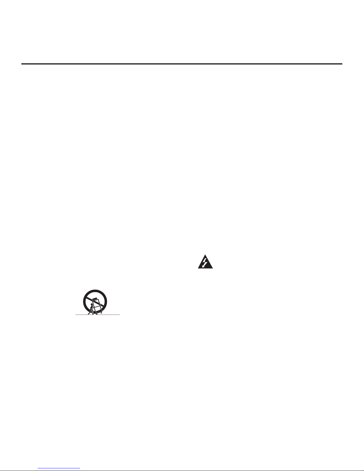
12. Use only with the cart, stand, tripod, bracket, or table
specified by the manufacturer or sold with the apparatus.
When a cart is used, use caution when moving the cart/
apparatus combination in order to avoid injury from tip-
over.
13.
Refer all servicing to qualied service personnel.
Servicing is required when the apparatus has been dam-
aged in any way, such as power-supply cord or plug is
damaged, liquid has been spilled or objects have fallen
into the apparatus, the apparatus has been exposed to
rain or moisture, does not operate normally, or has been
dropped.
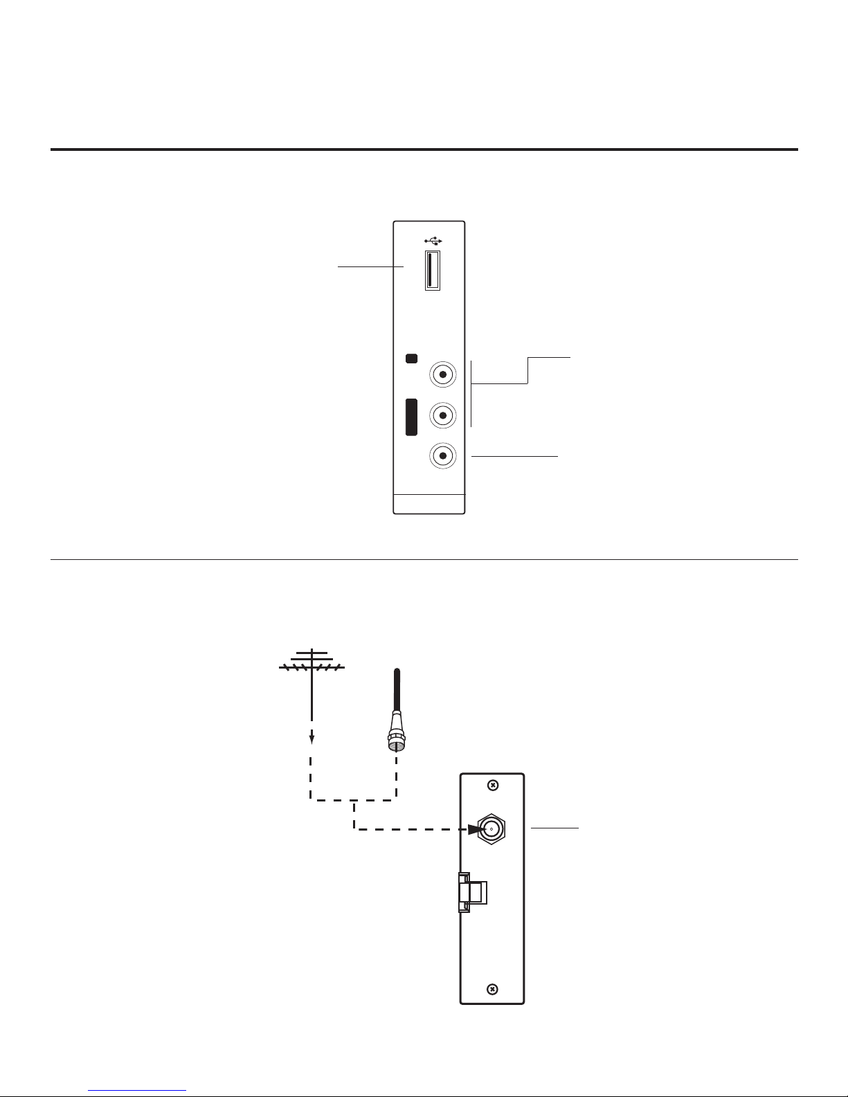
14. Never touch this apparatus or antenna during a thunder or
lighting storm.
15. When mounting a TV on the wall, make sure not to install
the TV by the hanging power and signal cables on the back
of the TV.
16. Do not allow an impact shock or any objects to fall into the
product, and do not drop objects onto the screen.
17. Power Cord
Caution: It is recommended that appliances be placed
upon a dedicated circuit; that is, a single outlet circuit
which powers only that appliance and has no additional
outlets or branch circuits. Check the specification page
of the Owner’s Manual to be certain.
Periodically examine the cord of your appliance, and if its
appearance indicates damage or deterioration, unplug it,
discontinue use of the appliance, and have the cord replaced
with an exact replacement part by an authorized servicer.
Protect the power cord from physical or mechanical abuse,
such as twisting, kinking, or pinching or being closed in a
door or walked upon. Pay particular attention to plugs, wall
outlets, and the point where the cord exits the appliance.
Do not use a damaged or loose power cord. Be sure to grasp
the plug when unplugging the power cord. Do not pull on the
power cord to unplug the TV.
18. Overloading
Do not connect too many appliances to the same AC power
outlet as this could result in fire or electric shock. Do not
overload wall outlets. Overloaded wall outlets, loose or dam-
aged wall outlets, extension cords, frayed power cords, or
damaged or cracked wire insulation are dangerous. Any of
these conditions could result in re or electric shock.
19. Outdoor Use/Wet Location
Warning: To reduce the risk of re or electrical
shock, do not expose this product to rain,
moisture or other liquids.
Do not touch the TV with wet hands. Do not install this prod-
uct near ammable objects, such as gasoline or candles, or
expose the TV to direct air conditioning.
Do not expose to dripping or splashing and do not place
objects lled with liquids, such as vases, cups, etc., on or over
the apparatus (e.g., on shelves above the unit).
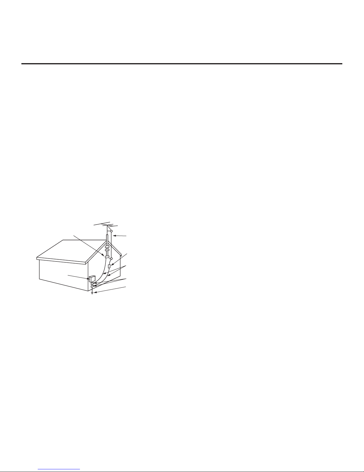
20. Grounding
Ensure that you connect the earth ground wire to prevent
possible electric shock (i.e., a TV with a three-prong ground-
ed AC plug must be connected to a three-prong grounded
AC outlet). If grounding methods are not possible, have a
qualified electrician install a separate circuit breaker. Do not
try to ground the unit by connecting it to telephone wires,
lightening rods, or gas pipes.
21. Disconnect Device
The mains plug is the disconnecting device. The plug must
remain readily operable.
As long as this unit is connected to the AC wall outlet, it is
not disconnected from the AC power source even if the unit
is turned Off.
(Continued on next page)
PORTABLE CART WARNING

4206-4185
IMPORTANT SAFETY INSTRUCTIONS
(Continued from previous page)
22. Outdoor Antenna Grounding
If an outside antenna or cable system is connected to the
product, follow the precautions below.
An outdoor antenna system should not be located in the
vicinity of overhead power lines or other electric light or
power circuits or where it can come into contact with such
power lines or circuits as death or serious injury can occur.
Be sure the antenna system is grounded so as to provide
some protection against voltage surges and built-up static
charges.
Article 810 of the National Electrical Code (NEC) in the
U.S.A. provides information with respect to proper grounding
of the mast and supporting structure, grounding of the lead-
in wire to an antenna-discharge unit, size of grounding con-
ductors, location of antenna-discharge unit, connection to
grounding electrodes, and requirements for the grounding
electrode.
Antenna Grounding According to NEC, ANSI/NFPA 70
23. Cleaning
When cleaning, unplug the power cord and wipe gently with
a soft cloth to prevent scratching. Do not spray water or
other liquids directly on the TV as electric shock may occur.
Do not clean with chemicals such as alcohol, thinners or
benzene.
24. Transporting Product
Make sure the product is turned Off and unplugged and that
all cables have been removed. It may take two or more people
to carry larger TVs. Do not press against or put stress on the
front panel of the TV.
25. Ventilation
Install the TV where there is proper ventilation. Do not install
in a confined space such as a bookcase. Do not cover the
product with cloth or other materials (e.g., plastic) while it is
plugged in. Do not install in excessively dusty places.
26. Do not touch the ventilation openings, as they may become
hot while the TV is operating.
27. If you smell smoke or other odors coming from the TV or
hear strange sounds, unplug the power cord, and contact an
authorized service center.
28. Do not press strongly on the panel with your hand or a sharp
object (e.g., a nail, pencil, or pen) or make a scratch on it.
29. Keep the product away from direct sunlight.
30. Dot Defect
The Plasma or LCD panel is a high technology product with
resolution of two million to six million pixels. In a very few
cases, you could see fine dots on the screen while you’re
viewing the TV. Those dots are deactivated pixels and do not
affect the performance and reliability of the TV.
31. Generated Sound
“Cracking”: A cracking noise that occurs while the TV is On or
when it is turned Off is generated by plastic thermal contrac-
tion due to temperature and humidity. This noise is common
for products where thermal deformation is required.
Electrical circuit humming/panel buzzing: A low level noise is
generated from a high-speed switching circuit, which sup-
plies a large amount of current to operate a product. It varies
depending on the product. This generated sound does not
affect the performance and reliability of the product.
32. For LCD TV
If the TV feels cold to the touch, there may be a small “flicker”
when it is turned On. This is normal; there is nothing wrong
with TV. Some minute dot defects may be visible on the
screen, appearing as tiny red, green, or blue spots. However,
they have no adverse effect on the TV’s performance. Avoid
touching the LCD screen or holding your finger(s) against it for
long periods of time. Doing so may produce some temporary
distortion effects on the screen.
Antenna Lead in Wire
Antenna Discharge Unit
(NEC Section 810-20)
Grounding Conductor
(NEC Section 810-21)
Ground Clamps
Power Service Grounding
Electrode System (NEC
Art 250, Part H)
Ground Clamp
Electric Service
Equipment

5
206-4185
Table of Contents
Safety Warnings................................2
Important Safety Instructions . . . . . . . . . . . . . . . . . . . .3
–
4
Table of Contents...............................5
Setup Checklist / Commercial Mode Setup Overview . . . 6
Pro:Centric TV Interactive Menu Features. . . . . . . . . . . . 7
LD330H Rear Jack Panel. . . . . . . . . . . . . . . . . . . . . . . . . 8
Side Connections Panel / RF Antenna Connection . . . . . 9
Installer Overview..............................10
Installer Remote Control Typical Key Functions . . . . . . 11
Commercial Mode Setup for Master TV ........12
–
13
Installer Menu .............................14
–
20
TV Setup Menus Overview . . . . . . . . . . . . . . . . . . . . . . 21
Adding Channel Icons / Custom Channel Labels
(2-5-4 + MENU Mode) ..........................22
Cloning Overview / Clonable Menu Features ......23
Cloning Procedures ........................24
–
28
Learning / Teaching a Master TV Setup using
a USB Memory Device . . . . . . . . . . . . . . . . . . . . . . . . 24
Learning / Teaching a Master TV Setup using
a TLL-1100A Clone Programmer . . . . . . . . . . . . .25
–
26
Learning / Teaching a Master TV Setup using
an LT2002 Clone Programmer . . . . . . . . . . . . . . .27
–
28
FTG Mode of Operation .....................29
–
33
FTG Mode Overview / Determining the TV
Operating Mode .............................29
Creating an FMA Configuration File using the FTG
Configuration Application . . . . . . . . . . . . . . . . . . . . . . 30
Teaching FMA Configuration to a TV . . . . . . . . . . . . . 31
Learning an FMA Configuration File from a TV . . . . . 32
Optional Manual Configuration / Setup for a TV. . . . . 33
FTG Configuration Application Utilities Overview . . .34
–
37
FTG Channel Map Configuration Utility. . . . . . . . . . . . 34
FTG Channel Map Editor . . . . . . . . . . . . . . . . . . . . . . 35
FTG Installer Menu Configuration Utility. . . . . . . . . . . 36
FMA Configuration Utility . . . . . . . . . . . . . . . . . . . . . . 37
References
Upgrading TV/PTC Software using a USB Memory
Device.......................................38
Downloading a Splash Screen using a USB Memory
Device.......................................39
Power Consumption Settings. . . . . . . . . . . . . . . . . . . . . 40
TV Camport Auto Sense Operation . . . . . . . . . . . . . . . . 41
TV Aux Input Configuration . . . . . . . . . . . . . . . . . . . . . . 42
Resetting a TV to Pass-through Mode. . . . . . . . . . . . . . 43
Troubleshooting ............................44
–
47
General Troubleshooting. . . . . . . . . . . . . . . . . . . . . . . 44
Troubleshooting Flow Chart . . . . . . . . . . . . . . . . . . . . 45
Commercial Mode Check / FTG Operation
Troubleshooting..............................46
Clone Programmer Troubleshooting . . . . . . . . . . . . . . 47
Glossary of Terms .............................48
Document Revision History / Notes . . . . . . . . . . . . . . . . 49
Back Cover...................................50
Note: Design and specifications subject to change without prior notice.
Notes
• Installer Menu content is intended for use primarily by qualied TV electronics technicians.
• Refer to the Owner’s Manual for additional information on TV features, specications, maintenance, and safety instructions.
• For additional information, contact your LG representative.

6206-4185
Installation and Setup Checklist
__ Unpack TV and all accessories.
__ Install batteries in remote control.
__ Install TV on VESA mount or stand.
Note: It may be advisable to make all cable
connections before installing on VESA mount or
stand, as appropriate.
Hardware Connections
__ Install any additional hardware as
appropriate to your institution, LAN, etc.
Cable Connections
__ Make all connections to rear jack panel and RF
antenna on MPI/PPV card.
__ Make all connections to signal, interactive
resources, and Aux sources, as appropriate.
Commercial Mode Setup
__ Complete Commercial Mode Setup (configure
all relevant Installer Menu items as required of
your institution and configure display features
for the end user).
Software Installation
__ Install or configure any software, as applicable,
for example, PPV, etc.
Setup Checklist / Commercial Mode Setup Overview
Setup Checklist
Commercial Mode Setup Overview
This document describes how to set up LD330H Pro:Centric™ TVs for Commercial Mode either while in
Pass-through Mode or Free-To-Guest (FTG) Mode.
Pass-through Mode
This mode allows you to configure a Master TV Setup for cloning purposes as well as external VOD/PPV
control. Use the Installer Remote to congure Installer Menu items as required for TV operation and set up
TV features (Channel, Picture, Audio, etc.). See pages 12 to 13 for detailed information.
FTG Mode
This mode enables Pro:Idiom
® decryption and also allows logical channel mapping of physical channels to
remove the need for dash tuning. FTG Conguration Application software is used to congure and/or edit
FTG Channel Map and FTG Installer Menu settings. See pages 29 to 37 for information on FTG Mode
options and using the FTG Conguration Application.

7
206-4185
Pro:Centric TV Interactive Menu Features
Important: Pro:Centric operation requires that Installer Menu items 098
PRO:CENTRIC and 119 DATA CHANNEL be set appropriately and that the TV be
in PPV or FTG Mode.
The interactive Pro:Centric TV enables guests—from the comfort of their hotel
rooms—to view and select from a complete listing of hotel services and amenities.
The Pro:Centric TV is connected to the hotel's billing computer, and service/amenities
charges are billed at the time of order.
Interactive amenities may include:
• Hotel information, news, and events
• Directory services (tourist attractions, restaurants, etc.)
• Reservation services (business meetings, tness, spa, etc.)
• Weather and trafc information
• Shopping services (delivery to guest room)
• Room service (menu ordering, memo service, morning wake up call, laundry, etc.)
• Ticketing services
• Check-out service (in the guest room)
• Gaming services
• E-mail resources/account access
Use the Installer Remote to operate both interactive menus and regular TV features.
Press PORTAL on the Installer Remote to access the interactive menus.
Note: Interactive menu options may vary, depending on Pro:Centric features enabled
for the site. The following are default interactive menus.
Channel Guide
Shows available TV networks and channels. When available, electronic program guide
(EPG) data indicates the channel and the program start and nish times.
Information
Typically displays hotel information, for example, photos of guest rooms, dining rooms,
business centers, facilities, etc., as well as information on local weather and attractions.
Information may also include resources, such as local school programs, run in coopera-
tion with the hotel.
Help
Provides help for navigating the interactive menus.
Watch TV
Removes the interactive menu from the screen and returns to the previously tuned TV
channel.
MENU
MUTE
VOL
CH
P
A
G
E
RETURN
INPUT
TV
ALARM TIMER
1 2 3
4 5 6
7 8
0
9
FLASHBK
PORTAL
ENTER
GUIDE
EXIT
INFO
EJECT
SAP
RATIO
CC
i

8206-4185
UPDATE
RESET
AUDIO IN
(RGB/DVI)
RS-232C IN
(SERVICE ONLY)
.....
....
..........
2
1
HDMI
/DVI IN
VIDEO
L/MONO-AUD
IO-R
AV IN 1
RGB IN (PC)
.....
.....
.....
..........
REMOTE
CONTROL
OUT
SPEAKER
OUT
8
HDMI
COMPONENT IN
R
L
PB
YPR
VIDEO
AUDIO
(
)
MPI
LD330H Rear Jack Panel
RGB IN (PC)
Connection for RGB
output from PC.
UPDATE
Restricted to
software updates.
RESET
Initiates a hardware
reset and switches
the TV to standby.
AUDIO/VIDEO IN 1
Connection for composite
audio/video output from
external device.
SPEAKER OUT (8Ω) *
Connect to 8 ohm self-powered
speaker input. Intended for special
applications, such as a powered bath-
room speaker with volume control.
REMOTE CONTROL OUT
IR output for controlling an
auxiliary device.
RS-232C IN
Use for downloading
software updates, etc.
COMPONENT IN
Connection for component
output from external device.
AUDIO IN (RGB/DVI)
Audio connection for
RGB or DVI device.
HDMI/DVI IN
Connection for HDMI/DVI
output from external device.
* This stereo jack provides a mono speaker
fixed-level, 1 watt output (audio +, audio -,
w/ground shield). Do NOT plug in a mono
connector, as this may damage the TV.
MPI
Enables an external MPI control
device (i.e., clone programmer,
VOD/PPV STB, etc.) to control
the TV.

9
206-4185
Side Connections Panel / RF Antenna Connection
AV IN 2
L/MONO -AUDIO- R
VIDEO USB IN
USB IN
Insert USB memory device
for software updates, cloning
purposes, or picture/music
entertainment, as applicable.
Antenna
or CATV
ANTENNA IN
RF Antenna Connection
Side Connections Panel
VIDEO IN
Connect to video output port on
external device (see Reference
section, “TV Camport Auto Sense
Operation,” for further information).
L/MONO-AUDIO-R IN
Connect to audio output jacks
on external device. For only
mono audio output, connect to
Left audio input.
A/V 2 Input
ANTENNA IN
Connect to Antenna/
CATV.

10 206-4185
Installer Overview
This is the Commercial Mode Setup Guide only.
Installer Menu / Commercial Mode Setup
To set up a Master TV for cloning purposes, you will need to know how
to enter the TV Installer Menu and make changes to the default values
as required. Similarly, to configure a TV’s Installer Menu settings in FTG
Mode, you will need to know how to access and use the FTG
Configuration Application utilities. If necessary, familiarize yourself with
the Installer Menu and how to make and save changes. Refer to page 14
for information on accessing the Installer Menu in Pass-through Mode.
Pages 15 to 20 describe Installer Menu items in detail. Refer to pages 29
to 37 for information on entering FTG Mode and using the FTG
Configuration Application utilities.
Installer Remote
The LG Installer Remote is supplied with and dedicated to operate the
TV. See next page for typical key functions. Some DVD and VCR con-
trols may be available for selected LG DVD/VCR products.
Cloning
Cloning refers to the process of capturing a Master TV Setup and trans-
ferring it to a Target TV. The Master TV’s clonable features need to be
configured as part of the Commercial Mode Setup. This is a critical step.
If the Master TV’s clonable features—channel icons or labels, digital font
options, etc.—are not set up correctly, the cloned TVs will all have prob-
lems. Pages 23 to 28 provide detailed information on cloning require-
ments and procedures.
Typical Installer Menu
MENU
MUTE
VOL
CH
P
A
G
E
RETURN
INPUT
TV
ALARM TIMER
1 2 3
4 5 6
7 8
0
9
FLASHBK
PORTAL
ENTER
GUIDE
EXIT
INFO
EJECT
SAP
RATIO
CC
i
xxLD330H PTC INSTALLER MENU
000 INSTALLER SEQ 000
UPN 000-000-000-000 ASIC 20E7
PTC V1.00.001 CPU V3.06.00
+ AAA
AAA +
Installing Batteries in Installer
Remote
• Open the battery compartment cover on the back side of the remote.
• Install two high-quality alkaline 1.5V AAA batteries. Never mix old
or used batteries with new ones. Install batteries matching correct
polarity as shown (+ with + and - with -).
• Replace the battery compartment cover.

11
206-4185
Installer Remote Control Typical Key Functions
MENU
MUTE
VOL
CH
P
A
G
E
RETURN
INPUT
TV
ALARM TIMER
1 2 3
4 5 6
7 8
0
9
FLASHBK
PORTAL
ENTER
GUIDE
EXIT
INFO
EJECT
SAP
RATIO
CC
i
NUMBER Buttons (0 - 9) & DASH
Use to enter a program number or channel.
Dash is used for sub-channel numbers such
as 2-1, 2-2, 9-1, 9-2, 100-3, 100-4, etc.
FLASHBK (FLASHBACK)
Returns to the previously tuned channel.
The LG Installer Remote illustrated below and throughout this document shows typical remote control functions and
is provided for reference only. This Installer Remote may vary from the Installer Remote supplied with the TV.
Color buttons access special functions
in some menus.
DVD/VCR BUTTONS
Controls some DVD players or
video cassette recorders.
EJECT
Ejects a USB memory device, CD,
DVD, VHS tape, as applicable.
VOLUME UP/DOWN
Increases/decreases sound level.
INFO
Displays channel information.
PORTAL
Displays and removes the interactive
menu.
MUTE
Switches sound ON or OFF.
CHANNEL/PAGE UP/DOWN
Changes the channel. Moves from
one full set of screen information to
the next.
Arrows (Up/Down/Left/Right) & ENTER
Use to navigate on-screen menus and
adjust TV settings to your requirements.
MENU
Displays the TV setup menus on the screen.
Also exits the on-screen menu system and
returns to TV viewing.
GUIDE
Displays and removes the electronic
program guide.
CC
Press to activate subtitles.
RETURN
Returns one level to the previous menu/
display.
SAP
Analog Mode: Selects MTS sound (Mono,
Stereo, or SAP). DTV Mode: Changes
audio language, if additional languages are
available. *
EXIT
Clears all on-screen displays and returns to
TV viewing.
POWER
Turns TV ON or OFF.
ALARM
Sets the time when the TV
will automatically turn itself ON.
TIMER
Sets the amount of time before the TV
automatically turns itself OFF.
INPUT
Selects RGB, HDMI/DVI1, HDMI2,
Component Input, AV1, and AV2 sources.
TV
Returns to the last TV channel
(from an Aux input).
SAP notes:
• If SAP is selected and no SAP is provided, sound
may not be heard on channel.
• Each analog channel may have its own SAP setting.
• Digital channels will reset to default audio language
with a power off/on.
*
RATIO
Adjusts the picture aspect ratio.

12 206-4185
Commercial Mode Setup for Master TV
117 FACT DEFAULT 001
003 BAND/AFC 00X
Typical TV Installer Menu
Note: The Installer Menu header will vary
depending on the TV you are setting up.
Adjust the settings for these
Installer Menu items.
1. Set Installer Menu items.
This step provides specic instruction only on the Installer Menu
items that should be set on a Master TV. Refer to pages 14 to 20
for detailed information on all Installer Menu items.
a) Make sure the TV is ON. Then, use the Installer Remote to
enter the TV Installer Menu: Press MENU repeatedly until
the on-screen setup menus lock up, and then press 9-8-7-6 +
ENTER.
b) Set Installer Menu item 117 FACT DEFAULT to 001 and press
ENTER on the Installer Remote.
This clears all Installer Menu custom settings, the channel
lineup, etc. and reloads the factory default settings. The value
will change back to 0 after the internal TV controller (Protocol
Translator Card [PTC]) has been restored to factory default
condition. This step ensures that the TV Channel Memory will
be the active channel lineup.
c) Set Installer Menu item 003 BAND/AFC, as appropriate.
• Broadcast: Set to 000. • HRC: Set to 002.
• CATV: Set to 001 (default). • IRC: Set to 003.
d) Set any other Installer Menu items that affect your TV program-
ming network to the required conguration. For example, enable/
disable Aux sources, set a Start Channel, etc.
e) After you have adjusted all required Installer Menu item
settings, press ENTER once on the Installer Remote to save
your changes; then, press ENTER again to exit the menu.
2. Set up TV features.
On-screen setup menus control the features of the TV (see page
21). Press MENU on the Installer Remote to access the setup
menus, and then set Channel, Picture, Audio, Lock, Time, etc.
options to the desired configurations. See also the Clonable Menu
Features list on page 23.
Note: If desired, you can run Auto Tuning (see step 3) prior to
completing this step.
3. Run Auto Tuning (Channel Search).
a) Search for all available analog and digital channels: Go to the
Channel Menu, select the Auto Tuning option, and follow the
on-screen instructions.
This section describes how to set up a Master TV for cloning purposes when the TV is in Pass-through Mode.
Note: Disconnect all Aux inputs. Under certain conditions, Auto Tuning (Channel Search) is disabled if
there is an Aux input active.
Note: Refer to FTG Mode information on pages 29 to 37 for information on entering FTG Mode and config-
uring/editing FTG Channel Map and FTG Installer Menu settings using the FTG Configuration Application.
(Continued on next page)
Set the TV features to the desired
configuration for the end user.
LOCK
PICTURE AUDIO
INPUT
OPTION
TIME
MY MEDIA
CHANNEL
xxLD330H PTC INSTALLER MENU
000 INSTALLER SEQ 000
UPN 000-000-000-000 ASIC 20E7
PTC V1.00.001 CPU V3.06.00

13
206-4185
028 CH. OVERIDE 000
After verifying the TV Setup, set Installer
Menu item 028 CH. OVERIDE to 000.*
Commercial Mode Setup for Master TV (Cont.)
DIGITAL
WXYZ
MONO STEREO SAP
19-3
Custom Text Label “WXYZ” created in
2-5-4 + MENU (Add Channel Label) Mode.
(Continued from previous page)
3. Run Auto Tuning (Channel Search). (continued)
b) Use the Channel Edit option in the Channel Menu to edit the chan-
nel lineup, as necessary, to include free to guest channels only.
• Add/delete channels per your system requirements. Note that if
Installer Menu item 103 ATSC TUNE MODE is set for Physical
Channel tuning (default and recommended setting), channels with
minor channel numbers higher than 255 will not transfer correctly
in step 4. If it is set for Virtual Channel tuning and either the major
or minor channel numbers are higher than 255, the channel(s) will
not transfer correctly in step 4.
• Use the Channel Label option in the Channel Menu to add familiar
channel trademarks/logos such as ABC, CBS, NBC, etc. to the
Channel-Time on-screen display. Identiable labels (logos) should
enable the end user to readily know what common networks are
available. (You can add the channel labels in this step, or you can
add channel labels or logos for channels without icons in step 5.)
4. Transfer the TV Setup to the internal TV Controller (PTC):
2-5-5 + MENU Mode
After the TV channel lineup has been edited and channel label icons
added, enter the Installer Menu. Once in the Installer Menu, press
2-5-5 + MENU on the Installer Remote to initiate the transfer of the
Master TV Setup to the PTC. The TV exits the Installer Menu and then
tunes through the channels in the channel lineup during the transfer.
When the transfer is complete, the TV tunes back to the channel that
was tuned before the transfer began.
Note: The maximum number of active channels that can be transferred
is 141. An attempt to transfer more than 141 channels will result in
erratic TV tuning operation.
5. Add Custom Channel and Aux Source Labels for Analog
Channels: 2-5-4 + MENU Mode
Enter the Installer Menu, and press 2-5-4 + MENU on the Installer
Remote. Add/edit custom text labels to channel on-screen displays.
Note that digital channels often have a broadcaster generated label
(see 2-5-4 + MENU procedural information on page 22). When you
are finished, press MENU to exit 2-5-4 + MENU Mode.
CHANNEL Enter
Move
Run Auto Tuning, edit channels, and select
familiar channel trademarks/logos using
Channel Menu options.
* This step prevents end users from
accessing channel settings (i.e., the
Channel Menu will be inaccessible/
grayed out).
Auto Tuning
Manual Tuning
Channel Edit
Channel Label
6. Verify the TV setup.
At this point, verify that the channel lineup, channel icons, and custom labels
are correct. Make sure the TV features are set per your requirements.
7. Lock the channel lineup.
Enter the Installer Menu. Set item 028 CH. OVERIDE to 000 and press ENTER
to lock the channel lineup and restrict access to the TV setup menus. Press
ENTER again to save your changes and exit the Installer Menu.*
The Master TV Setup is now ready to be copied to a USB memory device or a clone
programmer (see cloning information in this document).

14 206-4185
Installer Menu
Typical TV Installer Menu
Use the Installer Menu to set up or change operational settings.
Refer to the table starting on the next page for brief descriptions of Installer Menu
items. More detailed descriptions follow the table listing.
Accessing the Installer Menu
1. Make sure the TV is ON.
2. Using an Installer Remote, press MENU repeatedly until the on-screen
setup menus lock up, and then press 9-8-7-6 + ENTER to access the
Installer Menu.
The Installer Menu opens with item 000 INSTALLER SEQ 000.
Using the Installer Menu
Items 000 ~ 119 are accessible only upon entering the Installer
Menu. Refer to the table on pages 15 and 16 for an overview of Installer
Menu items, including item numbers, functions, ranges, and default values.
Installer Menu items not relevant to this TV series are not present on the
Installer Menu; therefore, some numbers are missing. For example, item 006
will not appear.
Navigation within the Installer Menu
Use the Up/Down arrow keys on the Installer Remote to sequence through
the available menu items, or access an item directly by keying in the line
number and then pressing MENU. For example, to access the SLEEP TIMER
option, which is item 015, press 0-1-5 + MENU.
Changing Installer Menu Settings
To change an Installer Menu item setting, use the Left/Right arrow keys on
the Installer Remote, or enter a value directly. Press ENTER to save the new
setting, or use the Up/Down arrow keys to navigate to a new Installer Menu
item if you have additional items to edit.
Exiting the Installer Menu and Activating Updates
After you have adjusted all required Installer Menu item settings, press
ENTER once on the Installer Remote to save your changes; then, press
ENTER again to exit the Installer Menu. Any changes you make will be
stored in non-volatile memory.
Note: Each time you exit the Installer Menu, all V-Chip (Parental Control)
settings in the TV are reset to their default values; that is, the Lock System,
if previously enabled from the Lock setup menu (see the Owner’s Manual
for additional information), will now be disabled, and the individual Parental
Control settings will be restored to default values.
xxLD330H PTC INSTALLER MENU
000 INSTALLER SEQ 000
UPN 000-000-000-000 ASIC 20E7
PTC V1.00.001 CPU V3.06.00

15
206-4185
Installer Menu (Cont.)
Installer Menu Items 000 through 071
Menu
Item Function Value Range Default Value Brief Description of Function and Comments
000 INSTALLER SEQ 0 ~ 3 0 Leave default set to 0.
001 POWER MANAGE 0 ~ 7 0 Sets number of hours of no activity before automatic shutoff.
002 AC ON 0 / 1 0 Set to 1 to enable Auto Turn ON when AC power is applied.
003 BAND/AFC 0 ~ 3 1 Selects Tuning Band: 0=Broadcast, 1=CATV, 2=HRC, 3=IRC
004 STRT CHANNEL 0 ~ 127, 255 255
Channel tuned when TV is turned ON. (Set to 255 to tune to channel
tuned before TV turned OFF.)
005 CHAN LOCK 0 / 1 0 If set to 1, cannot tune from current channel.
007 STRT VOLUME 0 ~ 63, 255 255 Volume level when TV is turned ON. (Set to 255 to use volume level
before TV turned OFF.)
008 MIN VOLUME 0 ~ 63 0 Sets minimum allowable volume setting.
009 MAX VOLUME 0 ~ 63 63 Sets maximum allowable volume setting.
010 MUTE DISABLE 0 / 1 0 Set to 1 to disable Mute Function.
011 KEY DEFEAT 0 / 1 0 Set to 1 to disable menu navigation keys on display panel.
015 SLEEP TIMER 0 / 1 1 Set to 1 to enable Sleep Timer.
016 EN TIMER 0 / 1 0 Set to 1 to enable On/Off Timers.
017 ALARM 0 / 1 1 Set to 1 to enable Alarm.
020 FEATURE LEVEL 0 ~ 1, 16 ~ 24 1 Determines an additional IR code scheme to which the TV will respond.
021 V-CHIP 0 / 1 1 Set to 1 to enable V-Chip (Parental Control) functions.
022 MAX BLK HRS 0 ~ 99 12 Sets number of V-Chip blocking hours.
023 CAPTION LOCK 0 / 1 0 Set to 1 to retain caption setting set before TV turned OFF.
028 CH. OVERIDE 0 / 1 1 If set to 0, limits direct access to favorite channels.
029 OLD OCV 0 / 1 0 Set to 1 to change MPI operation to OCV.
030 ACK MASK 0 / 1 0 If set to 1, changes MPI for some OCV boxes.
031 POLL RATE 20 ~ 169 94 Selects poll rate for MPI.
032 TIMING PULSE 186 ~ 227 207 Sets baud rate for MPI.
034 CAMPORT EN 0 / 1 1 Set to 1 to enable Video 2 input.
035 COMPPORT EN. 0 / 1 1 Set to 0 to disable HDMI 1. Set to 1 enable HDMI 1.
038 YPrPb EN. 0 / 1 1 Set to 1 to enable display panel Component Video 1 input jacks.
039 REAR AUX EN 0 / 1 1 Set to 1 to enable display panel Video 1 input jack.
040 AUTO CAMPORT 0 / 1 1 Set to 1 to automatically switch to Camport. If set to 1, STRT AUX SRCE
cannot be set to 2.
046 STRT AUX SRCE 1 ~ 6, 255 6 Sets the starting Aux source (if item 004 STRT CHANNEL is set to 0).
047 AUX STATUS 0 / 1 0 Set to 1 for MPI Aux source to be reported as a channel number instead of
Channel 0.
053 DIS. CH-TIME 0 / 1 0 Set to 1 to disable Channel-Time display.
069 EN. CH-T COL. 0 / 1 1 Set to 1 to enable custom color for the Channel-Time display.
070 FOR. CH-TIME 0 ~ 7 2 Chooses custom foreground color for the Channel-Time display.
071 BCK. CH-TIME 0 ~ 7 2 Chooses custom background color for the Channel-Time display.

16 206-4185
Installer Menu Items 073 through 119
Menu
Item Function Value Range Default Value Brief Description of Function and Comments
073 CH NOT AVBLE 0 / 1 0 If set to 1 and Channel Override is 0, “NOT AVAILABLE” message is displayed
when directly accessing a channel not in the favorite Channel List.
075 REVERT CH 0 / 1 0 If set to 1 and loss of MPI communication occurs, TV tunes to Start Channel.
078 UPN MSB 0 ~ 255 0 User programmable number, most significant byte.
079 UPN MSB-1 0 ~ 255 0 User programmable number, most significant byte - 1.
080 UPN MSB-2 0 ~ 255 0 User programmable number, most significant byte - 2.
081 UPN LSB 0 ~ 255 0 User programmable number, least significant byte.
082 CHKSM ERROR 0 / 1 1 Enforces rigid MPI checksum.
083 HANDSHK TIME 0 ~ 5 5 Relaxes MPI timing to be compatible with PC-based Windows-
controlled systems.
084 PERMANENT BLK 0 / 1 0 Removes block hours setting for Parental Control and makes block permanent.
087 REAR RGB EN.
0
/
1
/
17
1Set to 0 to disable RGB input. Set to 1 to enable RGB input.
Set to 17 for Auto Configure.
088 EN NOISE MUTE 0 / 1 1 If set to 1, audio is muted if no signal is present.
090 KEY LOCK 0 / 1 0 If set to 1, keyboard is locked out, IR is still functional.
091 YPrPb2 EN 0 / 1 1 Set to 1 to enable HDMI 2 input.
094 SAP MENU EN 0 / 1 1 Set to 0 to disable feature on Function Menu. Set to 1 to enable feature on
Function Menu.
096 DEF. ASP. RATIO 0 ~ 4 2 Sets default aspect ratio at power up. See detailed descriptions and item 106.
098 PRO:CENTRIC
0 ~ 2
0
Set to 0 to disable Pro:Centric operation. Set to 1 for Flash Mode. Set to 2 for
GEM (Java Application) Mode.
099 BACK LIGHTING
1 ~ 100,
101 ~ 200, 255
100
Sets the level of the TV picture back lighting. (See detailed descriptions.)
102 ATSC BAND 0 ~ 4 4 Selects ATSC band.
103 ATSC TUNE MODE 0 / 1 1 Set to 1 (default) for Physical Channel scan. Set to 0 for Virtual Channel scan.
104 START MINOR CH 0 ~ 255 0 Selects Minor Start Channel. Set to 0 for NTSC.
106 ASP RATIO LOCK 0 / 1 0 To retain set aspect ratio on power cycle, set to 1. Set to 0 for default ratio on
power cycle.
116 VIDEO MUTE EN 0 / 1 0 Set to 0 for Normal. Set to 1 for Blank.
117 FACT DEFAULT 0 / 1 0 Set to 0 for Normal. Set to 1 to load presets for all Installer Menu settings.
119 DATA CHANNEL 0 ~ 135 0 Set to 0 to disable. Set to the RF channel number of the Data Channel for
Pro:Centric or E-Z Installation data. (See detailed descriptions.)
Installer Menu (Cont.)

17
206-4185
Installer Menu (Cont.)
Detailed Descriptions of Installer Menu Items
000 - INSTALLER SEQUENCE
Species entry sequence to the Installer Menu.
0 = 9876 1 = 4321
2 = 1478 3 = 3698
001 - POWER MANAGE (Power Management)
Determines hours of no activity before automatic shutoff. The
Power Management function is for saving energy. If set to 0,
Power Manage is Off. Settings range from 0 ~ 7, with 1 ~ 7 rep-
resenting the hours that the unit will remain ON, unless there has
been activity from either the control panel or remote control.
002 - AC ON (AC Power Switchable)
If set to 1, this allows the TV to turn ON when AC power is ap-
plied. Pressing the ON button is not necessary. This is desirable
if the TV is plugged into a cable box or a power outlet controlled
by a wall switch. Use the Left/Right arrow keys to choose 0 or 1,
where 0 is the default (OFF), and 1 is ON.
Note: If set to 1 (ON), the TV does not respond to On/Off com-
mands from either the remote or the display control panel, and the
SLEEP TIMER is also nonfunctional.
003 - BAND/AFC (Band/Automatic Frequency Control)
There are four possible settings for this option:
0 = Broadcast 1 = CATV (default)
2 = HRC 3 = IRC
If some channels were not found by Auto Tuning (Channel
Search), select the appropriate Band setting here, and add the
channels using the Channel Edit option in the Channel Menu.
004 - STRT CHANNEL (Start Channel)
If active, this function allows you to determine the initial Major
Start Channel number when the TV is turned ON. This feature is
useful for an in-house information channel, since the TV would al-
ways select that channel when it is turned ON. Setting this item to
255 causes the last channel viewed when the TV was turned OFF,
to be the tuned to channel when the TV is turned ON again.
Note: For a digital Start Channel, always remember to set item
104 to the Minor Start Channel number.
255 = Last channel 1 ~ 125 = Major Ch. # 0 = Aux
126 = Map to Channel 3 127 = Map to Channel 4
005 - CHAN LOCK (Channel Lock)
Channel Lock is ideal if the system must always be on the same
channel. Changing channels with the Channel Up/Down or key-
pad numbers is impossible. Channel Lock is inactive if set to 0
(default).
Generally, this feature is used in connection with STRT CHAN-
NEL (Installer Menu item 004) where the Start Channel may, for
example, be set to 3 or 4. If the Start Channel is 3, then the TV
will remain locked on channel 3.
NOTE: For items 007, 008, and 009
For legacy reasons, the scale used is 0 – 63. The PTC software
will translate this to the 0 – 100 scale used by the TV.
To translate a TV volume level to the Installer Menu value, use
the following formula:
Installer Value = TV Value x 63
100
Enter only the whole number (disregard fractions).
007 - STRT VOLUME (Start Volume)
This function allows the Installer to determine the initial volume
level setting when the TV is turned ON. This feature is useful
for an in-house information channel, since the TV would always
select that volume level when it is turned ON. The range of values
are 0 - 63, 255. If 255 is selected, the current volume level will be
retained in memory when the TV is turned OFF; at turn ON, the
volume level will be automatically set at the previous or last level.
008 - MIN VOLUME (Minimum Volume)
This function determines the minimum volume level allowable
with the Volume (VOL) Up/Down control. In this way, for example,
someone cannot set the volume too low to hear. The value range
is from 0 to 63. Use the Left/Right arrow keys to change values.
The factory default is 0, which provides the full range of volume
control, if item 009 MAX VOLUME is also set to 63. It may be best
to set the same value on every TV.
Note: The minimum volume level cannot have a value setting
higher than the maximum volume level (described below).
009 - MAX VOLUME (Maximum Volume)
This function determines the maximum volume level allowable
with the Volume (VOL) Up/Down control. In this way, for example,
someone cannot set the volume level high enough to disturb oth-
ers. The value range is 0 to 63, with 63 as the default, which gives
the user the full range of volume control, if item 008 MIN VOLUME
is also set at 0. Use the Left/Right arrow keys to change values. It
may be best to set the same value on every TV.
Note: The maximum volume level cannot have a value setting
lower than the minimum volume level (described above).
010 - MUTE DISABLE
Enables or disables sound mute function. If set to 1, sound cannot
be muted. If set to 0, sound can be muted.
011 - KEY DEFEAT (Keyboard Defeat)
If set to 1, KEY DEFEAT prevents the end user from accessing
the on-screen menus from the display panel—MENU, ENTER,
and menu navigation keys do not function. If set to 0, those keys
do function.
Note: Users can always access the menus by pressing MENU on
the remote.

18 206-4185
Installer Menu (Cont.)
015 - SLEEP TIMER
If set to 1, the Sleep Timer feature may be used. If set to 0, the
Sleep Timer is not available.
016 - EN TIMER (Enable On/Off Timers) *
If set to 1, the Timer function is available to the end user and
enabled continuously. Set to 0 to disable On/Off timers.
Note: Clock must be set in order to use timers.
017 - ALARM *
Gives the installer the option of making the Alarm function avail-
able to the end user. If set to 1, the Alarm function is available to
the end user. Set to 0 to disable the Alarm function.
Note: Clock must be set before the Alarm function will work.
020 - FEATURE LEVEL
Determines an additional IR code scheme to which the TV will
respond, allowing for the use of unique IR codes based on “bed
number” in a multi-TV single room installation. First determine the
IR mode; then select the bed number.
IR Mode Bed # Values
Legacy (Hospital) 1 – 2 0 – 1
Multi-code Remote 1 – 9 16 – 24
Note: Multi-code remotes are not available for the current release.
For additional information, contact your LG representative.
021 - V-CHIP (Parental Control) *
Set to 1 to activate V-Chip (Parental Control) and have it available
to the end user to lter and control or otherwise restrict program-
ming content that can appear. Set to 0 to turn the V-Chip feature
Off (not available to user); no programming restrictions can be set.
022 - MAX BLK HRS (Maximum Block Hours) *
Sets hours from 0 to 99 for the maximum V-Chip (Parental Control)
block hours. Default setting is for 12 blocking hours.
023 - CAPTION LOCK
If set to 0, captions are OFF when the TV is turned ON. Set to 1 to
use the caption setting congured before the TV was turned OFF
when the TV is turned ON.
028 - CH. OVERIDE (Channel Override)
If set to 1, the user can select channels with either Channel Up/
Down or by direct keypad entry. If set to 0, only those channels
that are active in the TV’s memory can be selected.
029 - OLD OCV (On Command Video™)
Set to 1 for operation with systems from On Command Corporation.
* Only affects Function Menu if enabled by some PPV providers.
030 - ACK MASK
MPI Communication Parameter. Leave at default setting unless
changed by PPV provider. When set to 1, changes MPI for some
OCV boxes.
031 - POLL RATE
MPI Communication Parameter. Selects Poll Rate for MPI. Leave
at default setting unless changed by Pay-Per-View provider. Step
size of 16 ms.
032 - TIMING PULSE
MPI Communication Parameter. Leave at default setting unless
changed by Pay-Per-View provider. Sets baud rate. Step size of
4.3 uS.
034 - CAMPORT EN. (Camera Port Enable)
Set to 1 to enable Video 2 input on display panel. If set to 0, Video
2 input on display panel is not functional.
035 - COMPPORT EN. (Computer Port Enable)
Enable/disable TV display panel HDMI 1 input jack. Set to 0 to
disable HDMI1. Set to 1 to enable HDMI1.
038 - YPrPb EN. (Rear Component Video Enable)
Set to 1 to enable display panel rear Component Video input jacks.
Set to 0 to disable display panel rear Component Video input jacks.
039 - REAR AUX EN. (Rear Aux Enable)
Set to 1 to enable display panel rear Aux (Video 1) input. Set to 0
to disable display panel rear Aux (Video 1) input.
040 - AUTO CAMPORT
Set to 1 to automatically switch to Camport when equipment is
connected to side Video input. Set to 0 to disable side Video
automatic source selection. If set to 1, STRT AUX SRCE cannot
be set to 2.
046 - STRT AUX SRCE (Start Aux Source)
Sets the starting Aux source. When turned ON, the TV will tune to
starting Aux source if item 004 STRT CHANNEL is set to 0.
If item 040 AUTO CAMPORT is set to 0:
1 = Video 1 4 = RGB 255 = Last Aux
2 = Video 2 5 = HDMI 2
3 = HDMI 1 6 = Component
If item 040 AUTO CAMPORT is set to 1:
1 = Video 1 4 = RGB 6 = Component
3 = HDMI 1 5 = HDMI 2
047 - AUX STATUS
Set to 1 for MPI Aux source to be reported as a channel number
instead of channel 0. Set to 0 to disable Aux identication change.
Controls MPI status channel response for Aux inputs.

19
206-4185
Installer Menu (Cont.)
053 - DIS. CH-TIME (Disable Channel-Time)
Set to 1 to disable the Channel-Time display; Channel-Time display
will not appear. Set to 0 to enable the Channel-Time display.
069 - EN. CH-T COL. (Enable Channel-Time Custom Color)
Set to 1 to enable custom color for the Channel-Time display. Set
to 0 to disable custom color for the Channel-Time display.
070 - FOR. CH-TIME (Channel-Time Display Foreground Color)
Set according to Color Chart:
0 = Black 3 = Cyan 6 = Yellow
1 = Blue 4 = Red 7 = White
2 = Green 5 = Violet
Note: Applies only to “Channel Not Available” message if item
073 is set to 1 (enabled). If foreground color and background
color are the same, the menu background will be transparent.
071 - BCK. CH-TIME (Channel-Time Display Background Color)
Set according to Color Chart:
0 = Black 3 = Cyan 6 = Yellow
1 = Blue 4 = Red 7 = White
2 = Green 5 = Violet
Note: Applies only to “Channel Not Available” message if item
073 is set to 1 (enabled). If foreground color and background
color are the same, the menu background will be transparent.
073 - CH NOT AVBLE (Channel Not Available)
If set to 1 and item 028 CH. OVERIDE is set to 0, a “NOT AVAIL-
ABLE” message is displayed when directly accessing a channel
not in the channel scan list available in memory.
075 - REVERT CH (Revert to Start Channel)
If set to 1 and loss of MPI communication occurs, TV automati-
cally tunes to the specied Start Channel.
078 - UPN MSB (UPN Most Signicant Byte)
User programmable number, most signicant byte readable by
MPI command. Note: Not linked to serial number.
079 - UPN MSB-1 (UPN Most Signicant Byte-1)
User programmable number, most signicant byte-1 readable by
MPI command. Note: Not linked to serial number.
080 - UPN MSB-2 (UPN Most Signicant Byte-2)
User programmable number, most signicant byte-2 readable by
MPI command. Note: Not linked to serial number.
081 - UPN LSB (UPN Least Signicant Byte)
User programmable number, least signicant byte readable by
MPI command. Note: Not linked to serial number.
082 - CHKSM ERROR (Checksum Error)
Enforces rigid MPI checksum validation. Set to 1 for validation.
Set to 0 to disable (does not check checksum on MPI async port).
SPI is always checked.
083 - HANDSHK TIME (Handshake Time)
Adds an additional delay to the handshake time which is 64 msec,
thus relaxing MPI timing requirements to be compatible with PC-
based Windows controlled systems. Range is 0 - 5.
(Timeout = 25.5MS + [25.5 MS* Handshake time].)
084 - PERMANENT BLK (Permanent Block)
Allows Lock (Parental Control) blocking schemes to be permanent
by disabling the blocking hours function. Set to 1 to install Parental
Control restrictions permanently. Set to 0 for user-specied hours
control of blocking schemes.
087 - REAR RGB EN. (Rear RGB Enable)
Controls access to rear RGB input on TV. Set to 0 to disable RGB
input. Set to 1 to enable RGB input. Set to 17 to initiate a one-
time automatic conguration after an AC power cycle; otherwise,
automatic adjustment will be performed each time the RGB input
is accessed.
088 - EN NOISE MUTE (Enable Noise Mute)
If set to 1, audio mutes if no signal is present.
090 - KEY LOCK
If set to 1, display panel Channel, Volume, and Captions buttons
are disabled, Power button remains enabled. If set to 0, the Chan-
nel, Volume, Captions, and Power buttons are all enabled.
091 - YPrPb2 EN. (HDMI2 Enable)
Set to 0 to disable display panel HDMI2 input. Set to 1 to enable
DTV mode. Set to 2 to enable PC mode.
094 - SAP MENU EN (2nd Audio Program)
Set to 1 to enable SAP feature on Function Menu, if Function
Menu is available. Set to 0 to disable SAP feature on Function
Menu, if Function Menu is available.
096 - DEF. ASP. RATIO (Default Aspect Ratio)
Selects default aspect ratio at power up.
• Set to 0 for Set By System.
• Set to 1 for 4:3.
• Set to 2 for 16:9 (Factory Default).
• Set to 3 for Just Scan.
• Set to 4 for Zoom.
Note: Only applies if item 106 ASP RATIO LOCK is disabled, set
to 0.

20 206-4185
098 - PRO:CENTRIC
Selects the Pro:Centric Mode. Set to 0 (default) to disable
Pro:Centric operation. Set to 1 for Flash Mode. Set to 2 for GEM
(Java Application) Mode.
099 - BACK LIGHTING
Sets the TV screen brightness at power up. Default setting is 100.
• 1 - 100 Static Back Lighting
(1 = Dimmest picture, 100 = Brightest picture)
• 101 - 200 Dynamic Back Lighting
(101 = Dimmest picture, 200 = Brightest picture)
If set between 101 and 200, the TV automatically controls back
lighting depending upon the picture level of the current program. If
set to 255, back lighting is controlled via the Picture settings in the
TV’s setup menus.
102 - ATSC BAND
Sets up TV to receive different types of incoming signals:
0 = Broadcast, 1 = CATV, 2 = HRC, 3 = IRC, 4 = Same as NTSC.
103 - ATSC TUNE MODE
Sets ATSC tuning mode. Default set to 1 for Physical Channel
scan. Set to 0 for Virtual Channel scan.
104 - START MINOR CHANNEL
Sets Minor Start Channel number at power up. 0 = NTSC. If not
0, number selected is the digital channel’s Minor Start Channel
number.
106 - ASP RATIO LOCK (Aspect Ratio Lock)
Set to 1 to retain previous aspect ratio with power off. Set to 0 to
retain default aspect ratio with power off. See item 096 DEF. ASP.
RATIO above.
116 - VIDEO MUTE EN (Video Mute Enable)
Set to 0 for Normal. Set to 1 for Blank.
117 - FACT DEFAULT (Factory Default)
Set to 0 for normal. Set to 1 to load presets of all Installer Menu
item settings.
Warning: If set to 1, this will reload the factory de-
faults and clear the channel lineup, including any
assigned channel icons and custom channel labels.
119 - DATA CHANNEL
Set to 0 (default) to disable. Set to the RF channel number of the
Data Channel for Pro:Centric or E-Z Installation (splash screen,
configuration, or firmware) data.
Note: Pro:Centric updates are downloaded from the Pro:Centric
server to the TV when the TV is turned OFF. Also, while
Pro:Centric updates are in progress, it is not possible to turn the
TV ON. The TV may take several minutes to load EPG data after
the initial download of the Pro:Centric application. Subsequent
updates generally will take less than one minute.
Installer Menu (Cont.)
This manual suits for next models
1
Table of contents
Other LG Flat Panel TV manuals

LG
LG 47LX9500 User manual

LG
LG 32LC7D Series User manual

LG
LG 47LX9500 User manual

LG
LG 42LM3700 User manual

LG
LG 55GA7900 User manual

LG
LG 32LK335C User manual

LG
LG 37LG60 Series User manual

LG
LG 42LM6700 Assembly instructions

LG
LG M4201C-BA - - 42" LCD Flat Panel Display User manual

LG
LG M4210C-BH - - 42" LCD Flat Panel Display User manual