LG 20LH1DC1 User manual

20LH1DCl
Please read this manual carefully before operating
your set.
Retain it for future reference.
Record model number and serial number of the set.
See the label attached on the back cover and quote
this information to your dealer when you require
service.

NG/
This reminder is provided to call the CATV system
installer's attention to Article 820-40 of the National
Electric Code (U.S.A.). The code provides guidelines for
proper grounding and, in particular_ specifies that the
cable ground shall be connected to the grounding
system of the building, as close to the point of the
cable entry as practical.
IT IS FORBIDDEN TO CONNECT THIS TV
TO ANY TELECOMMUNICATION
NETWORK /TELEPHONE.
This equipment has been tested and found to
comply with the limits for a Class B digital device,
pursuant to Part ]5 of the FCC Rules.
These limits are designed to provide reasonable
protection against harmful interference when the
equipment is operated in a residential installation.
This equipment generates, uses and can radiate radio
frequency energy and, if not installed and used in
accordance with the instruction manual, may cause
harmful interference to radio communications.
However_ there is no guarantee that interference will
not occur in a particular installation.
If this equipment does cause harmful interference to
radio or television reception, which can be
determined by turning the equipment off and on, the
user is encouraged to try to correct the
interference by one or more of the following
measures:
• Reorient or relocate the receiving antenna.
• Increase the separation between the equipment
and receiver.
• Connect the equipment into an outlet on a circuit
different from that to which the receiver is
connected.
• Consult the dealer or an experienced radio/TV
technician for help.
Changes or modifications not expressly approved by
the party responsible for compliance could void the
user's authority to operate the equipment.
2

Do not attempt to modify this product in any way
without written authorization from LG Electronics
Corporation.
Unauthorized modification could void the user's
authority to operate this product.
Apparatus shall not be exposed to dripping or
splashing and no objects filled with liquids, such as
vases, shall not be placed on the apparatus.
THESE SERVICING INSTRUCTIONS ARE FOR USE BY
QUALIFIED SERVICE PERSONNEL ONLY. TO REDUCE
THE RISK OF ELECTRIC SHOCK, DO NOT PERFORM
ANY SERVICING OTHER THAN THAT CONTAINED
IN THE OPERATING INSTRUCTIONS UNLESS YOU
ARE QUALIFIED TO DO SO.
1. Do not put this product next to the patient's bed
where it can be reached by the patient.
2. Install product in such a way that patients will not
be able to touch this product.
3. This product should only be mounted on a wall.
When used outside of the U.S., it may be used HAR
cord with fitting of an approved agency is employed.
(When used outside of U.S., other power supply cords
may be used if the cord is approved by the local
regulating agency.)
Clean the exterior of this television by removing dust
with a lint-free cloth.
CAUTION: To avoid damage to the surface of the
television, do not use abrasive or chemical cleaning
agents.
Main plug is the disconnecting device. The plug must
remain readily operable.
YOUR PRODUCT HAS BEEN MANUFACTURED AND TESTED WITH YOUR SAFETY IN MIND. HOWEVER,
IMPROPER USE CAN RESULT IN POTENTIAL ELECTRICAL SHOCK OR FIRE HAZARDS. TO AVOID DEFEATING
THE SAFEGUARDS THAT HAVE BEEN BUILT INTO YOUR NEW PRODUCT, PLEASE READ AND OBSERVE THE
FOLLOWING SAFETY POINTS WHEN INSTALLING AND USING YOUR NEW PRODUCT, AND SAVE THEM FOR
FUTURE REFERENCE. OBSERVING THE SIMPLE PRECAUTIONS DISCUSSED IN THIS MANUAL CAN HELP YOU
GET MANY YEARS OF ENJOYMENT AND SAFE OPERATION THAT ARE BUILT INTO YOUR NEW PRODUCT.
3

SAFETY [NST S
IMPORTANT SAFETYINSTRUCTIONS
1. Read these instructions.
2. Keep these instructions.
3. Heed all warnings.
4. Follow all instructions.
5. Do not use this apparatus near water.
6. Clean only with dry cloth.
Z Do not block any ventilation openings. Install in accordance with the manufacturer's instructions.
8. Do not install near any heat sources such as radiators, heat registers, stoves, or other apparatus (including
amplifiers) that produce heat.
9. Do not defeat the safety purpose of the polarized or grounding-type plug. A polarized plug has two blades with
one wider than the other. A grounding type plug has two blades and a third grounding prong. The wide blade or
the third prong is provided for your safety. If the provided plug does not fit into your outlet, consult an
electrician for replacement of the obsolete outlet.
10. Protect the power cord from being walked on or pinched particularly at plugs, convenience receptacles, and the
point where they exit from the apparatus.
11. Only use attachments/accessories specified by the manufacturer.
12. Use only with the cart, stand, tripod, bracket, or table specified by the manufacturer, or sold with the apparatus.
When a cart is used, use caution when moving the cart/apparatus combination to avoid injury from tip-over.
PORTABLE CART WARNING
13. Unplug this apparatus during lightning storms or when unused for long periods of time.
14. Refer all servicing to qualified service personnel. Servicing is required when the apparatus has been damaged in
any way, such as power-supply cord or plug is damaged, liquid has been spilled or object have fallen into the
apparatus, the apparatus has been exposed to rain or moisture, does not operate normally, or has been dropped.
4
Outdoor Antenna Grounding
If an outside antenna or cable system is connected to the product, be sure the antenna or cable system is grounded
so as to provide some protection against voltage surges and built-up static charges. Article 810 of the National
Electrical Code (U.S.A.), ANSI/NFPA 70 provides information with regard to proper grounding of the mast and
supporting structure, grounding of the lead-in wire to an antenna discharge unit, size of grounding conductors,
location of antenna-discharge unit, connection to grounding electrodes, and requirements for the grounding
electrode.
Example of Grounding According to National Electrical Code Instructions
Ground Clamp _--"_k Antenna Lead in Wire
Antenna Discharge Unit
(NEC Section 810-20)
Grounding Conductor
(NEC Section 810-21 )
Ground Clamps
Power Service Grounding
_11_ I_t_ Electrode System (NEC
Art 250, Part H)
NEC - National Electrical Code

CONTENTS
WARNING /CAUTION ........................... 2
SAFETY INSTRUCTIONS ........................ 4
CONTENTS ............................................ S
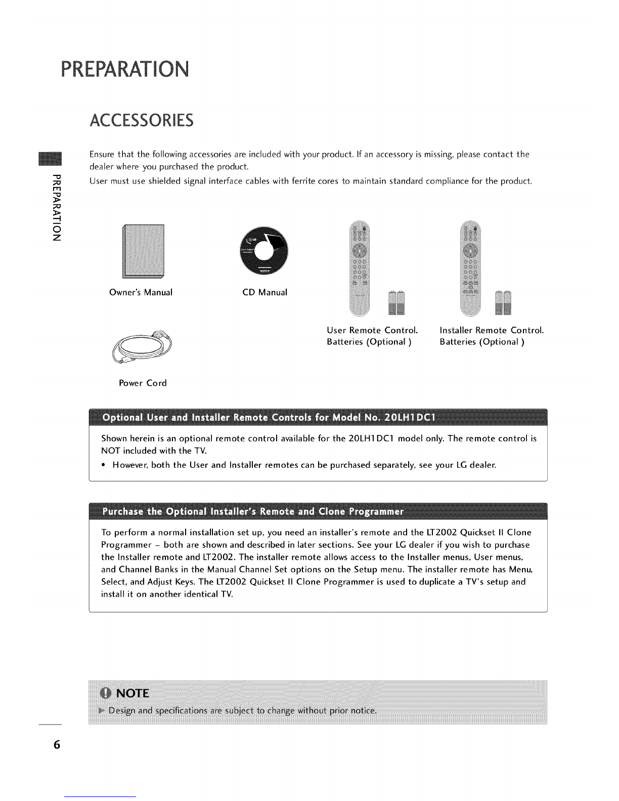
Accessories ................................................. 6
Front Panel Information ............................... 7
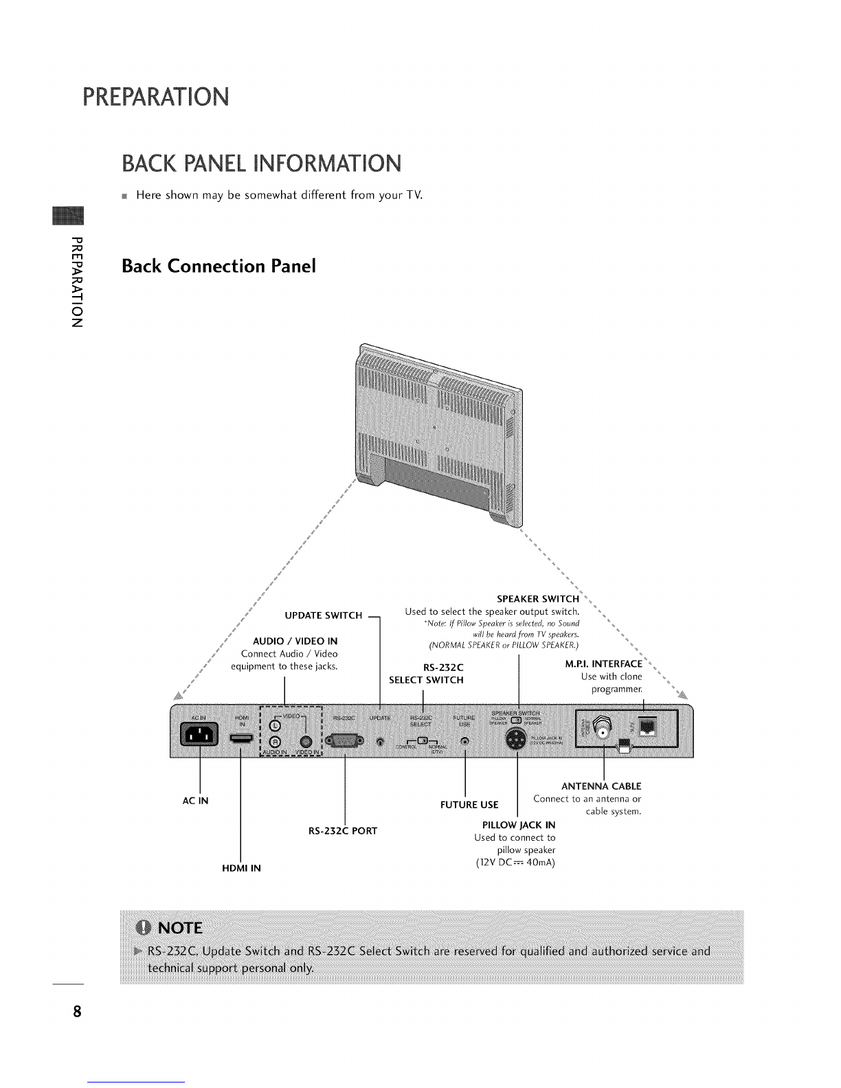
Back Panel Information ................................ 8
VESA Wall Mounting .................................... 9
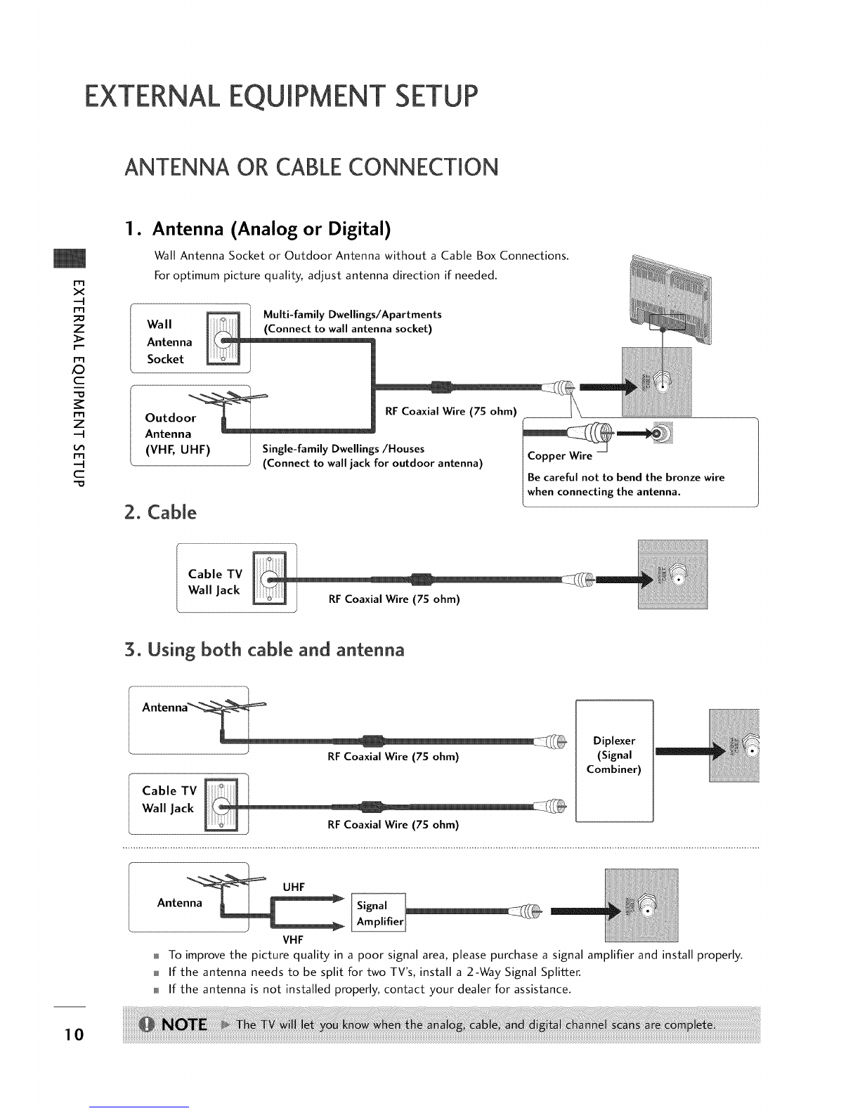
Antenna or Cable Connection ...................... 10
HD Receiver Setup ...................................... 11
DVD Setup ............................................... 13
VCR Setup ................................................ 14
PC Setup ................................................. 16
Pillow Speaker Setup .................................. 18
User Remote Control Button Functions .......... 19
Installer Remote Control Button Functions ..... 20
On-Screen Menus Selection .......................... 21
Channel Search .......................................... 22
Clock Setting ........................................... 26
Daylight Saving ................................... 28
Time Zone Settings .............................. 28
TV Activation Time Settings .................. 29
TV Deactivation Time Settings ............... 29
Auto Off ............................................ 30
Set Password &Lock System ....................... 31
Movie &TV Ratings .................................. 33
Caption /Text .......................................... 37
Preset Sound Settings .......................... 39
Sound Setting Adjustment-user Mode ...... 39
Sound Balance Setup ............................ 40
Automatic Volume Control Settings ........ 40
Analog Audio Settings .......................... 41
Digital Audio Language ....................... 41
Using External Speakers ........................ 42
Menu Language ................................... 42
Menu Transparency Settings ................... 43
Set ID .............................................. 43
Preset Picture Settings .............................. 44
Screen Format Adjustments .................. 4S
Noise Reduction ................................ 46
Film Mode Options ............................ 46
Managing the Channel Banks ....................... 47
Installer Overview ..................................... SO
Commercial Mode Setup ............................ 51
Cloning Connections/Learning Setup ............ 52
Clone Programmer/Learning Setup .............. 53
Cloning Connections/Teaching Setup ............ 54
Installer Menu .......................................... $6
Peference ................................................ 61
Troubleshooting ....................................... 66
Clone Troubleshooting Flow Chart .............. 70
TV Operating Check .................................. 71
Glossary of Terms ..................................... 72
Installer Quick Setup Guide ......................... 73 5

ACCESSORIES
"D
m
©
z
Ensure that the following accessories are included with your product. If an accessory is missing, please contact the
dealer where you purchased the product.
User must use shielded signal interface cables with ferrite cores to maintain standard compliance for the product.
Owner's Manual CD Manual
Power Cord
User Remote Control.
Batteries (Optional)
Installer Remote Control.
Batteries (Optional)
Shown herein is an optional remote control available for the 20LH1 DCl model only. The remote control is
NOT included with the TV.
• However, both the User and Installer remotes can be purchased separately, see your LG dealer.
To perform a normal installation set up, you need an installer's remote and the LT2002 Quickset II Clone
Programmer - both are shown and described in later sections. See your LG dealer if you wish to purchase
the Installer remote and LT2002. The installer remote allows access to the Installer menus, User menus,
and Channel Banks in the Manual Channel Set options on the Setup menu. The installer remote has Menu,
Select, and Adjust Keys. The LT2002 Quickset II Clone Programmer is used to duplicate a TV's setup and
install it on another identical TV.
6

FRONT PANELINFORMATION
+3 Here shown may be somewhat different from your TV.
m Using the front control panel to operate the TV.
Front Panel Controls
Remote Control Sensor
t
VOL I_
Power /Standby Indicator
Glows red in Standby mode.
Glows green when the TV is
turned on.
Glows orange in Sleep Timer
and/or Alarm mode.
t
@@@@@+o
y CH A TV/AV MENU O/I
s S
ss S
ATV Operation
Press the POWER button to turn the TV
on from standby mode.
s S
B Press MENU repeatedly to scroll through
menus. _e 0 0 0 0
( 411VOL I_ Y CH
ED
@ 0 ®o
TV]AV MENU 0]1
TTTT
C g A F
C Displays the current channel bank. Press
again to change banks.
DUse the CH (Channel) • or • button to
cycle through the available channels.
Use the VOL (Volume) • or I_ button to
adjust the sound level to your preference.
Insert the headphone plug to the
headphone socket of the set.
On-Screen Displays
See descriptions on page 21. On-screen displays will appear when the feature
is active or the function is being used.
"D
rfl
O
z
LED Color
RED
GREEN is flashing
GREEN
ORANGE
Action/Status
Power is Off (Standby)
Power On sequence is processing
Power is On
If Power is Off On Timer is set or Alarm is set
If Power is On Off Timer is set or Sleep Timer is set 7

PREPARATION
BACK PANELINFORMATION
Here shown may be somewhat different from your TV.
m
0
z
Back Connection Panel
G
,/ S UPDATE SWITCH 1
/AUDIO /VIDEO IN
Connect Audio /Video
equipment to these jacks.
SPEAKER SWITCH _
Used to select the speaker output switch.
*No_e: tf Pillow Speaker is selected, no Sound
wiltbe heard from TV speakers. _"_
(NORMAL SPEAKERor PILLOWSPEAKER.) _
RS-232C M.RI. INTERFAC _
SELECT SWITCH Use with clone
programmer.
AC IN
HDMI IN
RS-232C PORT
ANTENNA CABLE
Connect to an antenna or
FUTURE USE cable system.
PILLOW JACK IN
Used to connect to
pillow speaker
(12V DC---= 40mA)
8

VESAWALLMOUNTING
Here shown may be somewhat different from your TV.
Following are shown some examples of VESA standard lOOmm mounts. Since there are numerous types of stands
and mounts available, only a few are shown here. Refer to the instructions provided with the TV stand that will be
used to mount the TV.
General Guidelines: Choosing alocation for
installing a VESA Standard Mount Typical Wall Stud Type Mount with
Swivel Bracket
_0
rT1
_0
O
z
}_/ lOOmm ',_
Be sure the style of stand selected is capable of supporting
the weight of the TV.
If the mount will be on a wall, a typical wooden stud behind
the wall board would be the preferred choice for a location to
attach the wall mount. The wall mount location chosen should
be appro-priate for drilling holes and have available the
required power source as well as antenna/cable and other
equipment leads.
For pedestal-type mounts, a sturdy surface on a desk or other
similar fiat table-like surface would be the appropriate
location for mounting a pedestal-style TV stand. (Some
stands are portable and can be moved from one location to
another.) Be sure all safety considerations are followed.
Most stands are designed so that the wiring would be
threaded through the stand itself or a loop-through style
clamp so that the wiring is neatly bunched and not strung in
such a way as to create a potential hazard to the user.
Typical Pedestal Type Mount with
Swivel Bracket
9

EXTERNALEQUIPMENT SETUP
ANTENNA OR CABLECONNECTION
rT1
x
-4
rT1
_o
z
m
_D
c
-O
rT1
z
-4
m
-4
C
•Antenna (Analog or Digital)
Wall Antenna Socket or Outdoor Antenna without a Cable Box Connections.
For optimum picture quality, adjust antenna direction if needed.
Multi-family Dwellings/Apartments
Wall _(Connect to wall antq!nna socket)
Antenna
Socket
Outdo RFCoaxial Wire (75 ohm)
Antenna
(VHF, UHF) Single-family Dwellings/Houses
(Connect to walljack for outdoor antenna)
2. Cable
Be careful not to bend the bronze wire
when connecting the antenna.
Cable TV
Wall Jack RFCoaxial Wire (75 ohm)
3. Using both cable and antenna
RF Coaxial Wire (75 ohm)
Cable TV
Wall Jack RFCoaxial Wire (75 ohm)
Diplexer
(Signal
Combiner)
VHF
To improve the picture quality in a poor signal area, please purchase a signal amplifier and install properly.
If the antenna needs to be split for two TV's, install a 2-Way Signal Splitter.
If the antenna is not installed properly, contact your dealer for assistance.
10

To prevent the equipment damage, never plug in any power cords until you have finished connecting all
equipment.
HD RECEIVERSETUP
This TV can receive Digital Over-the-air/Cable signals without an external digital set-top box. However, if you do
receive digital signals from a digital set-top box or other digital external device, refer to the figure as shown below.
When connecting HDM[ cable
1. How to connect
Connect the digital set-top box to HDMI IN jack on the
set.
No separated audio connection is necessary.
HDMI supports both audio and video.
rT1
x
-4
rT1
_o
z
m
_D
c
-O
rT1
z
-4
m
-4
c
-O
.How to use
Turn on the digital set-top box.
(Refer to the owner's manual for the digital set-top box.)
Select HDMI input source by using the 1 -3-3 buttons
on the remote control. (Refer to p.65)
11

EXTERNALEQUIPMENT SETUP
m
x
-4
m
_o
z
r--
m
_D
c
mO
m
z
-4
m
-4
C
When connecting HDMi to DVi cable
•How to connect
Connect the DVI output of the digital set-top box to the
HDMI IN jack on the set.
t_ Connect the audio of the box to
output digital set-top
the AUDIO IN jack on the set.
•How to use
Turn on the digital set-top box. (Refer to the owner's manual
for the digital set-top box.)
Select HDMI input source by using the 1 -3-3 buttons on
the remote control. (Refer to p.6S)
12

DVD SETUP
When connecting HDMJ cabJe
1. How to connect
Connect the HDMI output of the DVD to the HDMI IN
jack on the set.
No separated audio connection is necessary.
HDMI supports both audio and video.
2. How to use
Select HDMI input source by using the 1-3-3 buttons on
the remote control. (Refer to p.65)
Refer to the DVD player's manual for operating instructions.
m
x
-4
m
z
m
£3
c
"10
m
z
-4
m
-4
c
13

EXTERNALEQUIPMENT SETUP
VCR SETUP
To avoid picture noise (interference), leave an adequate distance between the VCR and TV.
If the 4:5 picture format is used; the fixed images on the sides of the screen may remain visible on the screen.
This phenomenon is common to all manufactures and in consequence the manufactures warranty does not cover
the product bearing this phenomenon.
m
x
-4
m
z
m
_D
c
-D
m
z
-4
m
--4
C
-D
When connecting with an antenna
1. How to connect
Connect the RF antenna out socket of the
VCR to the ANTENNA/CABLE socket on
the set.
Connect the antenna cable to the RF
antenna in socket of the VCR.
oHow to use
Set VCR output switch to 5 or 4 and then tune
TV to the same channel number.
Wall Jack
Antenna
Insert a video tape into the VCR and press PLAY
on the VCR. (Refer to the VCR owner's manual.)
14

When connecting with a RCA cable
1. How to connect
Connect the VIDEO jacks between TV and VCR. Match
the jack colors (Video = yellow, Audio Left = white, and
Audio Right = red)
2. How to use
Insert a video tape into the VCR and press PLAY on the
VCR. (Refer to the VCR owner's manual.)
Select AV input source by using the 1 -3-1 buttons on
the remote control. (Refer to p.65)
m
x
m
z
m
_D
c
-O
m
z
m
c
"O
1S

EXTERNALEQUIPMENT SETUP
PC SETUP
m
x
--4
m
_o
z
I"
m
/O
c
-O
m
z
--4
m
--4
C
"O
When connecting HDMi to DVi cable
1. How to connect
Connect the DVI output of the PC to the HDMI IN
jack on the set.
Connect the PC audio output to the AUDIO IN jack on
the set.
2. How to use
Turn on the PC and the TV.
Select HDMI input source by using the 1 -3-3
buttons on the remote control. (Refer to p.6S)
16

m
x
-.q
m
z
r'--
m
aD
c
_r
m
z
-.q
m
-.q
c
Supported Display Specifications
HDMI/DVI-PC mode HDMI/DVI-DTV mode
31.469 59.94
3Z879 60.31
48.363 60.00
47.776 59.87
4Z720 59.799
4Z130 59.65
31.469 59.94
31.500 60.00
44.960 59.94
45.000 60.00
33.720 59.94
33.750 60.00
17

EXTERNALEQUIPMENT SETUP
PILLOWSPEAKERSETUP
r.,tl
x
-4
I"tl
z
I"tl
,O
c
3=
I"tl
z
-4
m
-4
c
"O
Here shown may be somewhat different from your TV.
1. How to connect
Connect the PILLOW JACK IN the Pillow Speaker output
jack on the back of the TV.
Connect an accessory pillow speaker or wired remote
control unit to this 6-pin jack.
Select PILLOW SPEAKER on the rear panel of the TV.
*Note: If the pillow Speaker switch is set to Pillow Speaker, no sound will be
heard from the TV speakers. I_pillow speaker switch is set to the Pillow Speaker
position, Auto Volume will be grayed out and not accessible on the Sound menu.
Use a pillow speaker by Curbell, Model A-16455-02 or
other UL recognized pendant control bearing the warning:
"Risk of fire if used in oxygen enriched atmosphere.
Keep pendant control away from oxygen equipment."
Controlling the TV with Serial Data
The TV is capable of being controlled by a single-wire,
serial data signal. This is a LG patented technology and is
being implemented by certain brands of "smart" pillow
speakers, such as Curbell's "GEN-II" models.
Pillow Speaker Interface
This connector furnishes three control lines and an audio
output. A patient-pendant remote control, or
entertainment audio and nurse call system may be
connected here. All lines are isolated from the AC power
line and earth ground. (Opto-isolators isolate the control
lines, and a transformer isolates the audio. There are no
relays or inductive components in the control lines.)
Pin No. Purpose
1 External TV On/Off switch.
2 (Not used.)
3; External Channel Up switch or Data in.
4 Common connection for control, data, and audio output.
Impedance to earth ground is a 10-meg resistor in parallel
with a 1100 pf capacitor.
5 Isolated audio output. Nominal 14-ohm source impedance
with short circuit protection. Intended for a pillow speaker
with a low-impedance pad-type volume control.
6External Channel Down switch.
k-- :
[ _ i[[
l T4V Back J
_:' , "_.
Pillow speaker not included
with TV.
1 _ TV ON/OFF
2 OPEN
3 I CHAN UP/DATA IN
4 [ COMMON
5 I AUDIO OUT
6 I CHAN DOWN
Controlling the TV with Mechanical Switches
Pin 4 (common) is momentarily connected to pin 1,
3, or 6via push-action switches to control On/Off
and Channel Up/Down. These pins are at +13 volts
DC (when measured from pin 4) with the switches
open. Current draw is 8mA when a switch is closed.
(This operation is identical to previous LG models
using the 5-Wire Interface except that only +7
volts DC was supplied and current draw was only
2.5 mA.)
18

TV/CHANNEL CONTROL
USERREMOTECONTROL BUTTON FUNCTIONS
A brief list of the buttons on the optional patient remote control and what they do.
MUTE __
Turns sound Off and On, while the picture
remains.
BANK
Press and repeat to select a Channel
Memory Bank - - 1,2, 3, or 4 (Standby).
CHANNEL PREVIEW
Displays available TV channels, and (if
active) the Guest Parental Control menu:
set V-Chip blocks to restrict both analog
and digital programming.
• Aux Channel allows the guest to select
the Audio /Video inputs. (Use the A/V
jacks on the back of the TV as a source).
SAP
Selects MTS sound: Mono, Stereo, and
SAP in analog mode. Change the audio
language in DTV mode.
[-] BUTTON
When selecting a digital broadcast
channel, key in the Main channel
number followed by the -> [-] -> then the
sub channel number. Analog channels do
not contain a sub channel number.
TIMER
Press repeatedly to select a preset time to
automatically shut the TV off.
POWER
Turns TV On or Off.
GUIDE
Use to view DTV program information.
CC (Closed Captioning)
Press to access closed captions.
INFO
Press to display current program information.
l OLUME /CHANNEL /OK (Enter)
Increase or decrease sound level.
Select available channels.
Select on-screen menu items and change
menu values.
_-[ NUMBER BUTTONS
Use for direct channel entry.
FLASHBK (Flashback)
Use to return to the last channel viewed.
j LARM
Use to go to the Alarm menu. Set a time for
the TV to turn itself on.
I BED l/BED 2 (*See Note Below)
Determines the code set transmitted, Bed 1
or Bed 2. Switch setting must correspond to
item 27, HOSPITAL MODE setting in the TV's
Installer Menu.
N
-1-
Z
C_
-4
N
"1"
Z
Z
r"""
N
O
Z
-4
O
r"""
Optional Patient
Remote Control
19

WATCHING TV/CHANNEL CONTROL
INSTALLERREMOTECONTROL BUTTON FUNCTIONS
A brief list of the buttons on the optional installer remote and what they do.
N
-1-
Z
C_
--4
N
"1"
Z
Z
rrl
r"""
N
O
Z
--4
O
r"""
MUTE
Turns sound Off and On, while the picture
remains.
BANK
Press and repeat to select a Channel
Memory Bank - - 1,2, 3 or 4 (Standby).
SAP
Selects MTS sound: Mono, Stereo, and
SAP in analog mode. Change the audio
language in DTV mode.
CHANNEL PREVIEW
Displays available TV channels, and (if
active) the Guest Parental Control menu:
set V-Chip blocks to restrict both analog
and digital programming.
• Aux Channel allows the guest to select
the Audio /Video inputs. (Use the A/V
jacks on the back of the TV as a source).
[-] BUTTON
When selecting a digital broadcast
channel, key in the Main channel
number followed by the -> [-] -> then the
sub channel number. Analog channels do
not contain a sub channel number.
TIMER
Press repeatedly to select a preset time to
automatically shut the TV off.
MENUPress to display the main on-screen menu.
Optional Installer
Remote Control
POWER
Turns TV On or Off.
GUIDE
Use to view DTV program information.
CC (Closed Captioning)
Press to access closed captions.
INFO
Press to display current program information.
VOLUME /CHANNEL /OK (Enter)
Increase or decrease sound level.
Select available channels.
Select on-screen menu items and change
menu values.
NUMBER BUTTONS l
Use for direct channel entry.
FLASHBK (Flashback)
Use to return to the last channel viewed.
ALARM
Use to go to the Alarm menu. Set a time for
the TV to turn itself on.
ADJ A T _11_
User ADJ (adjust) Up/Down menu arrows,
Left/Right to change the selected option.
BED 1/BED 2 (*See Note Below)
Determines the code set transmitted, Bed 1
or Bed 2. Switch setting must correspond to
item 2Z HOSPITAL MODE setting in the TV's
Installer Menu.
20
Other manuals for 20LH1DC1
2
Table of contents
Other LG Flat Panel TV manuals

LG
LG 47LS4500 Assembly instructions

LG
LG 42LB50C User manual

LG
LG 42LM3700 User manual

LG
LG M4201C-BA - - 42" LCD Flat Panel Display User manual

LG
LG M5201C User manual

LG
LG 55GA6400 User manual

LG
LG 60LS5750 User manual

LG
LG 47LX9500 User manual

LG
LG 42LM3700 Assembly instructions

LG
LG M4210C-BH - - 42" LCD Flat Panel Display User manual