LG 20LS7D - - 20" LCD TV User manual

LCD TV
SERVICE MANUAL
CAUTION
BEFORE SERVICING THE CHASSIS,
READ THE SAFETY PRECAUTIONS IN THIS MANUAL.
CHASSIS : LJ71A
MODEL : 20LS7D 20LS7D-JA
website:http://biz.LGservice.com

- 2 -
CONTENTS
CONTENTS .............................................................................................. 2
SAFETY PRECAUTIONS ........................................................................ 3
SPECIFICATION ...................................................................................... 4
ADJUSTMENT INSTRUCTION ............................................................... 7
TROUBLE SHOOTING .......................................................................... 11
WIRING DIAGRAM ................................................................................ 17
BLOCK DIAGRAM ................................................................................. 18
EXPLODED VIEW .................................................................................. 20
REPLACEMENT PARTS LIST .............................................................. 22
SVC. SHEET ...............................................................................................

- 3 -
SAFETY PRECAUTIONS
Many electrical and mechanical parts in this chassis have special safety-related characteristics. These parts are identified by in the
Schematic Diagram and Replacement Parts List.
It is essential that these special safety parts should be replaced with the same components as recommended in this manual to prevent
Shock, Fire, or other Hazards.
Do not modify the original design without permission of manufacturer.
General Guidance
An isolation Transformer should always be used during the
servicing of a receiver whose chassis is not isolated from the AC
power line. Use a transformer of adequate power rating as this
protects the technician from accidents resulting in personal injury
from electrical shocks.
It will also protect the receiver and it's components from being
damaged by accidental shorts of the circuitry that may be
inadvertently introduced during the service operation.
If any fuse (or Fusible Resistor) in this TV receiver is blown,
replace it with the specified.
When replacing a high wattage resistor (Oxide Metal Film Resistor,
over 1W), keep the resistor 10mm away from PCB.
Keep wires away from high voltage or high temperature parts.
Before returning the receiver to the customer,
always perform an AC leakage current check on the exposed
metallic parts of the cabinet, such as antennas, terminals, etc., to
be sure the set is safe to operate without damage of electrical
shock.
Leakage Current Cold Check(Antenna Cold Check)
With the instrument AC plug removed from AC source, connect an
electrical jumper across the two AC plug prongs. Place the AC
switch in the on position, connect one lead of ohm-meter to the AC
plug prongs tied together and touch other ohm-meter lead in turn to
each exposed metallic parts such as antenna terminals, phone
jacks, etc.
If the exposed metallic part has a return path to the chassis, the
measured resistance should be between 1MΩand 5.2MΩ.
When the exposed metal has no return path to the chassis the
reading must be infinite.
An other abnormality exists that must be corrected before the
receiver is returned to the customer.
Leakage Current Hot Check (See below Figure)
Plug the AC cord directly into the AC outlet.
Do not use a line Isolation Transformer during this check.
Connect 1.5K/10watt resistor in parallel with a 0.15uF capacitor
between a known good earth ground (Water Pipe, Conduit, etc.)
and the exposed metallic parts.
Measure the AC voltage across the resistor using AC voltmeter
with 1000 ohms/volt or more sensitivity.
Reverse plug the AC cord into the AC outlet and repeat AC voltage
measurements for each exposed metallic part. Any voltage
measured must not exceed 0.75 volt RMS which is corresponds to
0.5mA.
In case any measurement is out of the limits specified, there is
possibility of shock hazard and the set must be checked and
repaired before it is returned to the customer.
Leakage Current Hot Check circuit
1.5 Kohm/10W
To Instrument’s
exposed
METALLIC PARTS
Good Earth Ground
such as WATER PIPE,
CONDUIT etc.
AC Volt-meter
IMPORTANT SAFETY NOTICE
0.15uF

- 4 -
1. Application range
This specification sheet is applied to the 20”/ 23” Wide LCD
Digital TV used LJ71A chassis.
2. Requirement for Test
Each part is tested as below without special appointment.
(1) Power : Standard input voltage (100V, 50/60Hz)
(2) Specification and performance of each parts are followed
each drawing and specification by part number in
accordance with BOM
(3) The TV set must be operated for about 20 minutes prior to
the adjustment.
3. Test method
(1) Performance : LGE TV test method followed
(2) Demanded other specification
Safety : JQA Specification
EMC : JQA Specification
SPECIFICATION
NOTE : Specifications and others are subject to change without notice for improvement
.
4. General Specification(TV)
No Item Specification Remark
1 Video input applicable system NTSC-M/ ISDB-S
2 RF Input Channel 1) VHF : 1 ~ 12
2) UHF : 13 ~ 62
3) CATV : C13 ~ C38
4) Terr. digital : 000 ~ 999 (Logical CH Number)
5) BS digital : 000 ~ 999 (Logical CH Number)
6) CS digital : 000 ~ 999 (Logical CH Number)
3 Input Voltage 100V~, 50/60Hz
4 Market Japan
5 Tuning System FS
6 Operating Environment Temp : 0 ~ 40 deg
Humidity : 10~90 %RH
7 Storage Environment Temp : -20 ~ 50 deg
Humidity : 10~90 %RH
8 Display LCD Module

1 Viewing Angle R/L 80/80
<CR≥10> U/D 70/70
2 Luminance Luminance (cd/m2) 350 450
3 Contrast Ratio CR 600 700 All white / All black
4 CIE Color Coordinates WHITE Wx Typ. 0.295 Typ. In AV input
Wy -0.03 0.305 +0.03 PSM : Dynamic
RED Rx 0.640 White (100 IRE)
Ry 0.330
GREEN Gx 0.290
Gy 0.600
BLUE Bx 0.150
By 0.060
5. Module Specification
5.1. 20”LCD Module (AUO T200XW02 V0)
5.1. Optical characteristic specifications
- 5 -
1 Display area 443.61 (H) *249.41(V) mm
2 Outline dimension 472.0 (H) x 276.5 (V) x23.0 (D) mm Typ
3 Number of Pixels 1366 (H) x 768(V) 1Pixel=3RGB Cells
4 Cell pitch 324.75μm (H) x 324.75μm (V) μm 1Pixel=3RGB Cells
5 Color arrangement RGB vertical stripe
6 Weight(net) 3 Kg Max
7 Operating Environment Temperature 0 ~ 50 deg
Humidity 10 ~ 90 %
8 Storage Environment Temperature -20 ~ 60 deg
Humidity 10 ~ 90 %
9 Electrical Interface LVDS
10 Back light Unit 6 CCFL (6 lamps)
11 R/T 8ms Typ.
No. Item Min Typ. Max Unit Remark
No. Item Specification
Min Typ. Max Remark

- 6 -
7. Component Video Input (Y, PB, PR)
No Resolution H-freq(kHz) V-freq.(kHz) Pixel clock(MHz) Proposed
1 720*480 15.73 59.94 13.500 SDTV, DVD 480I
2 720*480 15.75 60.00 13.514 SDTV, DVD 480I
3 720*480 31.47 59.94 27.000 SDTV 480P
4 720*480 31.50 60.00 27.027 SDTV 480P
5 1280*720 44.96 59.94 74.176 HDTV 720P
6 1280*720 45.00 60.00 74.250 HDTV 720P
7 1920*1080 33.72 59.94 74.176 HDTV 1080I
8 1920*1080 33.75 60.00 74.250 HDTV 1080I
6. Model Specification
No. Item Specification Remark
1 Analog-terrestrial Broadcasting system NTSC-M
RF Input Channel VHF : 1~12
UHF : 13~62
CATV : C13~C38
2 Digital-terrestrial Broadcasting system ISDB-T
RF Input Channel 000~999 CH. Logical CH Number
3 Digital-BS/SC Broadcasting system ISDB-S
RF Input Channel 000~999 CH.
4 Video Input NTSC-3.58 NTSC4.43/PAL/PAL60/SECAM -> No Guarantee
5 S-Video Input NTSC-3.58 NTSC4.43/PAL/PAL60/SECAM -> No Guarantee
6 D-terminal Input Y/ Pb/Pr(D4: 480i/480P/720P/1080i) 576i/576p/720p(50Hz)/1080i(50Hz) -> No Guarantee
7 HDMI Input HDMI
8 Audio Input L/R Input 3EA : CVBS, S-video, D-terminal
9 Digital Optical Audio output AAC 5.1c Output Available for Digital TV only
PCM 2ch Output
10 Modem 2400bps(max)
11 Conditional Acess System B-CAS System
12 EPG
13 DATA Broadcasting
8. HDMI input (DTV)
No Resolution H-freq(kHz) V-freq.(kHz) Pixel clock(MHz) Proposed
1 720*480 15.73 59.94 13.500 SDTV 480I
2 1440*480 15.75 60.00 27.027 SDTV 480I
3 720*576 15.63 50.00 13.500 SDTV 576I
4 1440*576 15.63 50.00 27.000 SDTV 576I
5 720*480 31.47 59.94 27.000 SDTV 480P
6 720*480 31.50 60.00 27.027 SDTV 576P
7 720*576 31.25 50.00 27.000 SDTV 576P
8 1280*720 37.5 50.00 74.250 HDTV 720P
9 1280*720 44.96 59.94 74.176 HDTV 720P
10 1280*720 45.00 60.00 74.250 HDTV 720P
11 1920*1080 33.72 59.94 74.176 HDTV 1080I
12 1920*1080 33.75 60.00 74.250 HDTV 1080I
13 1920*1080 28.125 50.00 74.250 HDTV 1080I

- 7 -
ADJUSTMENT INSTRUCTION
1. Application Range
This specification sheet is applied to 20”/ 23” LCD TV which is
manufactured in TV (or Monitor) Factory or is produced on the
basis of this data.
2. Specification
1) The adjustment is according to the order which is
designated and which must be followed, according to the
plan which can be changed only on agreeing.
2) Power Adjustment: 100V, 50/60Hz
3) Magnetic Field Condition: Nil.
4) Input signal Unit: Product Specification Standard
5) Reserve after operation: Above 30 Minutes
6) Adjustment equipments: Color Analyzer(CA-210 or CA-
110), Pattern Generator (MSPG-925L or Equivalent), DDC
Adjustment Jig equipment, SVC remote control
3. Main PCB check process
* APC - After Manual-Insert, executing APC
3.1. Download
1) Execute ISP program “Mstar ISP Utility”
2) Click “Config” and set as below
3) Click “Auto Detect” and check “OK” message.
If “Error” is displayed, check connecting computer, jig, and
set again.
4) Click “Connect”.
If “Can’t” is displayed, check connecting computer, jig, and set.
5) Click “Read” tab, and then load download file(XXXX.bin) by
clicking “Read”.
6) Click “Auto” tab and set as below.
7) click “Run”.
8) After downloading, check “OK” message.
3.2. ADC Process
(1) COMPONENT input ADC
1) Component Gain/Offset Adjustment
- Convert to Component in Input-source
- Signal equipment displays
Impress Resolution 480P
MODEL : 212 in Pattern Generator
(480p Mode, Y : 100%, Pb/Pr : 100%)
PATTERN : 08 in Pattern Generator
(MSPG-925 Series)
- Adjust by commanding AUTO_COLOR_ADJUST
(0xF1) 0x00 0x02 instruction.
2) Confirmation
- We confirm whether “0x8E” address of EEPROM
“0xB4” is “0xAA” or not.
- If “0x8E” address of EEPROM “0xB4” isn’t “0xAA”, we
adjust once more.
- We can confirm the ADC values from “0x00~0x05”
addresses in a page “0xB4”.
3.3. Function Check
(1) Check display and sound
- Check Input and Signal items. (cf. work instructions)
1) TV
2) AV1 : CVBS
3) AV2 : CVBS/ S-Video
4) COMPONENT : D-terminal(D4)
5) HDMI
* Display and Sound check is executed by Remote control.
filexxx.bin
(5)
(7) .......OK
(6)

- 8 -
4. Total Assembly line process
4.1. Adjustment Preparation
- Above 30 minutes H/run in RF no signal
4.2. Confirm color coordinate of component
(1) Set Input to COMPONENT.
(2) Input signal : 480P
Full white 216/255 gray level (85 IRE Model : 212, Pattern :
78 at MSPG925L)
(3) Set PSM : Dynamic / CSM : Cool
(4) Confirm whether x = 0.306±0.03, y = 0.304±0.03 or not.
4.3. Confirm color coordinate of AV2
(1) Set Input to AV2
(2) Input signal : CVBS, NTSC-M
Full white 216/255 gray level (85 IRE, Model : 201, Pattern
: 78 at MSPG925L)
(3) Set PSM : Dynamic / CSM : Cool
(4) Confirm whether x = 0.276±0.03, y = 0.283±0.03 or not.
4.4. Other quality
- Confirm that each items satisfy under standard condition that
was written product spec.
- Confirm Video and Sound at each source
(1) Analog TV
- Select input Analog TV and check whether picture is
displayed or not.
(2) Terrestrial Digital TV
- Select input Terrestrial Digital TV and check whether
picture is displayed or not.
* Use ISDB-T Signal Generator(LG3802) and Stream
(Ch11, NHK1, Freq.473.143MHz) stored in the Generator.
Caution) It’s necessary to connect B-CAS CARD when you
check this source.
(3) Satellite Digital TV (BS/CS)
Select input BS satellite Digital TV and check whether
picture is displayed or not.
Caution) It’s necessary to connect B-CAS CARD when you
check this source.
(4) AV1
- Select input AV1 (CVBS) and whether picture is displayed
or not.
(5) AV2
- Select input AV2 (CVBS/S-video) and whether picture is
displayed or not
(6) COMPONENT
- Select input COMPONENT and whether picture is
displayed or not.
(7)HDMI
- Select input HDMI and whether picture is displayed or not
4.5. Power Consumption
1) Press “EYE” button on LG Adjust remocon and check
whether LED color is amber or not.
2) Press “POWER” button on LG Ajust remocon to enter
Stand-by mode.
3) Check the power consumption. (Under 1W)
4.6. HDCP setting
(High-Bandwidth Digital Contents Protection)
- Connect HDMI cable to HDMI jack.
- Input HDCP key with HDCP-key-in-program.
- HDCP key value is stored on EEPROM(AT24C64) which is
E00~F20 addresses of 0xBC~0xBE page.
- AC off/on and on HDCP button of MSPG925 and confirm
whether picture is displayed or not of using MSPG925.
- HDCP key value is different among the sets.
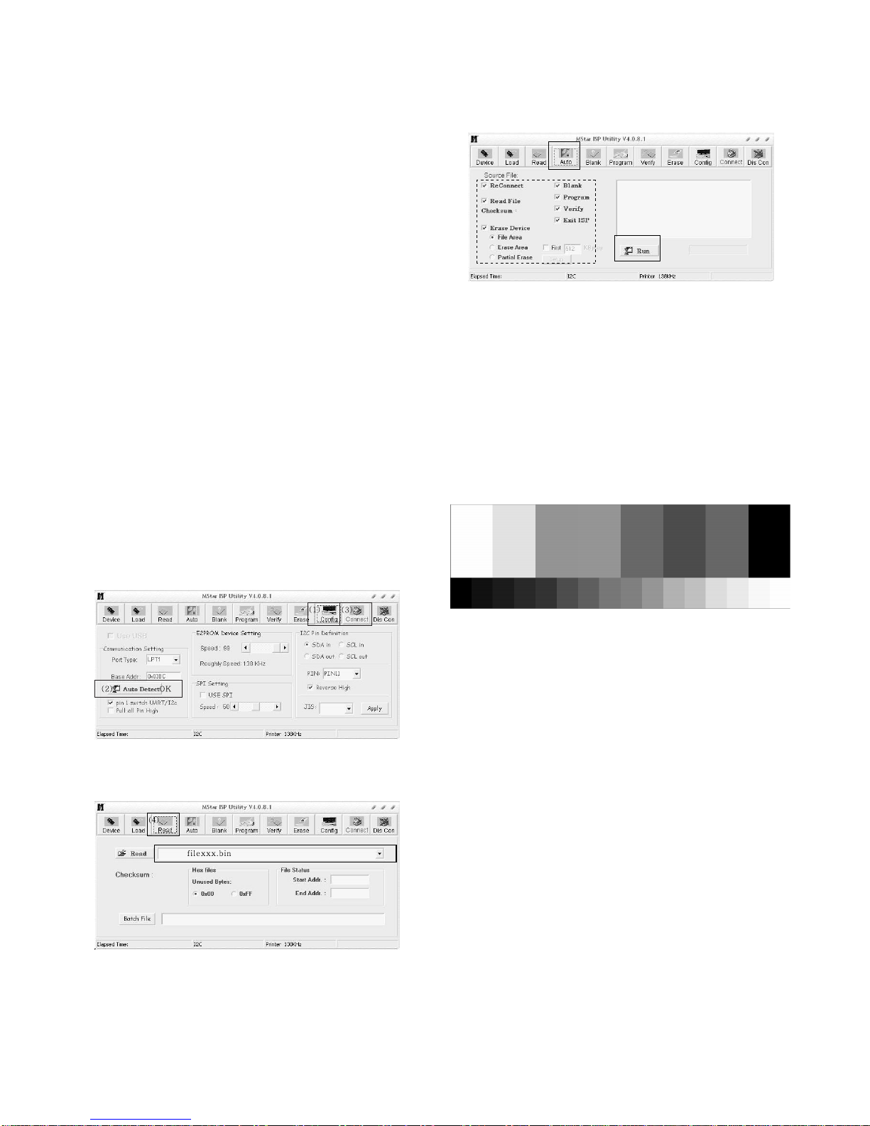
4.7 DDC EDID Write
1) Connect HDMI Signal Cable to HDMI Jack.
2) Write EDID DATA to EEPROM(24C02) by using DDC2B
protocol.
3) Check whether written EDID data is correct or not. (refer to
Product spec).
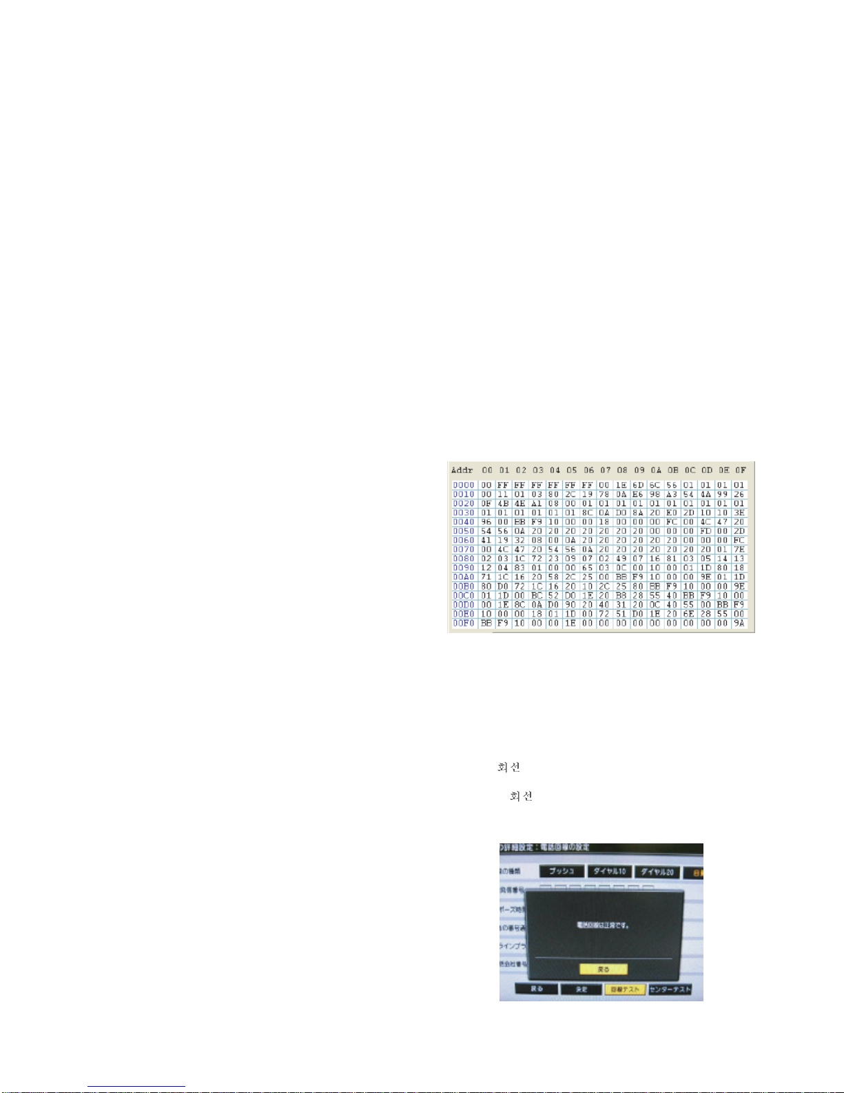
<DIGITAL DATA 256Byte>
4.8. Modem Communication check
1) Connect a telephone wire between TV and Terminal
adapter (MN128mini-SV1)
2) Press “EYE” button on LG Adjust Remocon and chek
whether Power LED color is amber or not.
3) Press “MODE” button on LG Adjust Remocon and check
whether the other LED color is red or not.
4) After “ test” is progressing automatically in DTV menu,
check whether the message is displayed or not as below.
(During “ test”, color of the other LED is green.)
If the message is displayed, Modern communication test is
OK.

4.9. Hi-POT
Confirm whether is normal or not when between power
board’s as block and GND is impacked on 1500 Vac or 2121
Vdc/1sec for one second.
(Judgment condition
: 1) Supply DC voltage -> set cut-off current to 10mA
2) Supply AC voltage -> set cut-off current to 100mA)
4.10. Insulation
After setting above condition, supply 500Vdc and then
measure the insultion resistance(Spec : above 4M ohm)
4.11. Outgoing condition Configuration
- Analog/ Digital TV Initializing
1) Press “EYE” button on LG ADJUST REMOCON.
(If Pressed “EYE” button on LG ADJUST REMOCON,
Color of Power LED will be Amber)
2) Press “IN-STOP” button on LG ADJUST REMOCON. It is
executed 3~15 procedure automatically by Software
program.(If pressed “IN-STOP” button, Color of “
” LED will be RED)
3) After Initializing is finished, the TV set turns off
automatically.
4.10. Option data setting(SVC OSD setting)
* Tool/Area option confirm.
If Tool option(17280)/Area option(0) is not, change the Tool
option(17280)/Area(0) value compulsorily.
5. Adjustment Command
5.1. Adjustment Commands(LENGTH=84)
- 9 -
TOOL OPTION 17280
AREA OPTION 0
OPTION 1 6
OPTION 2 2
OPTION 3 2
OPTION 4 0
OPTION 5 9
FACTORY ON E0 00 00 Factory mode on
FACTORY OFF E2 00 00 Factory mode off
EEPROM ALL INIT. E4 00 00 EEPROM All clear
EEPROM Read E7 00 00 EEPROM Read
EEPROM Write E8 00 data EEPROM Write by some values
COLOR SAVE (R/G/B cutoff, Drive, Contrast, Bright) EB 00 00 Color Save
H POSITION 20 00 00 – 100 They have different range each mode, FOS Adjustment.
V POSITION 30 00 00 – 100
CLOCK 90 00 00 – 100
PHASE 92 00 00 – 100
R DRIVE 16 00 00 – FF Drive adjustment
G DRIVE 18 00 00 – FF
B DRIVE 1A 00 00 – FF
R CUTOFF 80 00 00 – 7F Offset adjustment
G CUTOFF 82 00 00 – 7F
B CUTOFF 84 00 00 – 7F
BRIGHT 10 00 00 – 3F Bright adjustment
CONTRAST 12 00 00 - 64 Luminance adjustment
AUTO_COLOR_ADJUST F1 00 02 Auto COLOR Adjustment
CHANGE_COLOR_TEMP F2 00 0,1,2,3 0 : COOL, 1 : NORMAL, 2 : WARM, 3 : USER
FACTORY_DEFAULT F3 00 00 Factory mode off & II_SW is “1” & Input change to “ TV”
AUTO_INPUT CHANGE F4 00 0,1,2,4 0:ATV, 1:Video1, 2:Video2, 3:DTV, 4:D-TERMNAL, 5:HDMI
VAL DescriptionADRCMD(hex)Adjustment Contents

- 10 -
5.2 EEPROM DATA READ
(1) Signal Table
(2) Command Set
* Purpose : To read the appointment Address of E2PROM by
128(80h)-byte
5.3. E2PROM Data Write
(1) Signal Table
LEN : 84h+Bytes
CMD : 8Eh
ADH : E2PROM Slave Address(A0,A2,A4,A6,A8), Not
00h(Reserved by BufferToEEPROM)
ADL : E2PROM Sub Address(00~FF)
Data : Write data
(2) Command Set
* Purpose
1) EDID write : 16-byte by 16-byte, 8 order (128-byte)
write(TO “00 – 7F” of “EEPROM Page A4”).
2) FOS Default write : 16-mode data (HFh, HFl, VF, STD,
HP, VP, Clk, ClkPh, PhFine) write.
3) Random Data write : write the appointment Address of
E2PROM.
5.4. VRAM Read
1) Send CMD(70h) to read Video RAM value from MICOM
And save its value to 128-Bytes Buffer.(Common Buffer for
the use of EDID)
2) Delay 500ms. (Time to Wait and Read Video RAM from
MICOM)
3) Be transmitted the contents of MICOM’s 128-bytes Buffer to
PC. (128th Data is the CheckSum of 127-bytes data :
That’s OK if the value of adding 128-bytes Data is Zero)
128 Bytes
Delay 100ms
Data 128
EEPROM READ E7 A0 0 0-Page 0~7F Read
80 0-Page 80~FF Read
A2 0 1-Page 0~7F Read
80 1-Page 80~FF Read
A4 0 2-Page 0~7F Read
80 2-Page 80~FF Read
A6 0 3-Page 0~7F Read
80 3-Page 80~FF Read
Adjustment contents CMD(hex) ADH(hex) ADL(hex) Details
EEPROM WRITE E8 94 16-Byte Write
84+n n-byte Write
Adjustment contents CMD(hex) ADH(hex) Details

TROUBLE SHOOTING
1. No Power (LED indicator off) : [A] Process
- 11 -
Check 12V or
ST_5V of Power B/D. Fail
Pass
Check short of Main B/D
or Change Power B/D.
Check Output of
IC1000, IC1004. Fail Check short of
IC100, Q308.
Pass
Pass
Fail Re-soldering or Change
defect part of IC100, Q308.
Change IC1000, IC1004.
Pass
Change IC1006, IC1005.
Check Output of
IC1006, IC1005. Fail Check short of
Q308, TU600, IC500. Fail Re-soldering or Change
defect part of Q308,
TU600, IC500.
Pass
Pass
Change IC1002, IC1003.
Change LED Assy.
Check Output of
IC1002, IC1003.
Pass
Check LED Assy.
Pass
Check P306 Connector.
Fail Check short of
IC100, IC400.
Fail
Fail Re-soldering or Change
defect part of IC100, IC400.

- 12 -
2. No RASTER : [B] Process
Check LED status
On Display Unit.
Fail
Pass
Repeat A PROCESS.
Check Panel Link
Cable or Module.
Pass
Fail Change Panel Link Cable or Module.
Check Inverter
Connector or
inverter.
Fail Change Inverter Connector or Inverter.
Pass
Change IC100
Check Output of
Q308.
Pass
Check the LVDS
Output of IC100
Pass
Check Input source Cable and Jack.
Fail
Change Module.
Fail
Fail Change Q308.

- 13 -
3. No RASTER on DTV Signal
Repeat [A,B] process
Pass
Check the input/
output of R918.
Fail Check the P901.
Pass
Re-soldering or change the defect part.
Check the X100
Check the input/
output of R127.
Pass
Check the input/
output of IC100
Pass
Check and Change the Digital board.
Fail
Fail Re-soldering or Change the defect part.

- 14 -
4. No Raster on Component Signal
Repeat [A, B]
process.
Pass
Check the input/
output of R806.
Fail Check the J801.
Pass
Re-soldering or change the
defect part, Check the X100.
Check
the input/output
of R121.
Pass
Check the
input/output of IC100.
Pass
Check input source cable and jack.
Fail
Fail Re-soldering or Change the defect part.

5. No Raster on HDMI Signal
6. No Raster on AV (Video,
S-Video) Signal 7. No Raster on TV(RF) Signal
- 15 -
Repeat [A, B]
process.
Pass
Check the input/
output of IC100.
Fail Re-soldering or change the
defect part, Check the X100.
Pass
Check input source cable and jack.
Repeat [A, B]
process.
Pass Check the output
of TU600.
Pass Pass
Fail Check 5V of TU600.
Re-Soldering or change
the defect part.
Check the
input/output of L702,
R954, R948.
Fail Change L702, R954,
R948.
Pass
Check input/output
of IC100.
Pass
Fail Re-soldering of Change defect part.
Check the X100.

8. No sound
- 16 -
Check the input
Source.
Fail
Pass
Change the source input.
Check input/Output
of IC100.
Fail
Pass
Re-soldering of Change the defect part.
Check the X110
Check the input/
output of IC500 Fail Re-soldering or Change
the defect part.
Pass
Check the Speaker
Pass
Check the Speaker wire.
Fail Change Speaker.

- 17 -
WIRING DIAGRAM
Wiring Part List
6631T25026L12
6631T20010F13
EAD3850980111
6631900013B10
6631900048B9
EAD385990018
6631T20033C7
EAD385989016
T
5
EAD3
EAD3 3
85
5
9
99
880
0
1
01
4
6631 2
2
2R3
66319000
0
12C2
EAD3
3
8599101
Part No.No.
2
1
2
34
7 8
13
9
5
6
11
12
10

- 18 -
Connect t o next page
BLOCK DIAGRAM
1. Digital

- 19 -
HDMI
CVBS(AV1)
SP (R)
SP (L)
Audio
Amp
(YDA138)
LCD
Module
20LCD:AUO 20inch
23LCD:AUO 23inch
128MB
SDRAM
(HY5DU281622)
SYSTEM
EEPROM (64k)
Y/C
Y/Pb/Pr
4M bit
Serial
Flash
Memory
(MX25L4005A)
EXT_ISP
TMDS Signal & IIC
D4
DIGITAL Board Audio
SIDE AV Audio
EEPROM
(2k)
D-SUB
Tuner
TAFT-H003F
VIDEO
SIF
L
R
LVDS Signal
L/R
Scaler+Video
Decorder
(LGE9689AD-LF)
L/R
Power Vol- Vol+ Ch- Ch+ SourcePower Vol- Vol+ Ch- Ch+ Source
LED(G)
IR
LED(R/G)
IR receiver
Y/Pb/Pr
DIGITAL
Board
SIDE S-VIDEO
Y&C
D4 Audio L/R
CVBS Audio L/R
SIDE CVBS(AV2) Y&C
RS232
2. Analog

- 20 -
300 200 LV1
550
600
601
551
120
590
591
910
920
900
930
570 560 561 580
520 521 400
531
530
581
EXPLODED VIEW
A21
A2
Other manuals for 20LS7D - - 20" LCD TV
4
This manual suits for next models
1
Table of contents
Other LG LCD TV manuals