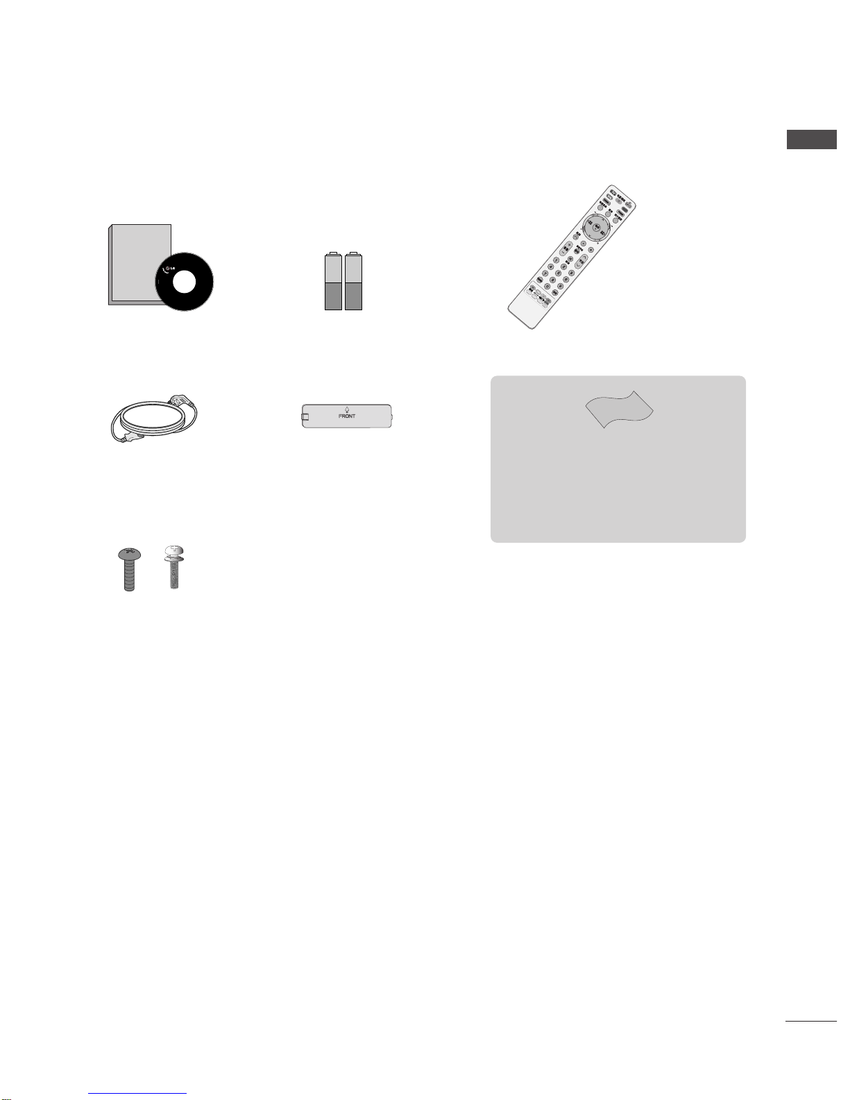
LG 42LG70ED User manual

1. Trim Size (Format) : 185 mm x 260 mm
2. Printing Colors : 1 Color (BLACK)
3. Stock (Paper)
•Cover : Coated paper, S/W 150 g/㎡
•Inside : Uncoated paper, 백상지 60 g/㎡
4. Printing Method : Off-set
5. Bindery : Perfect bind
6. Language : EN (1)
7. Number of pages : 108 pages
Changes
3.
REV.
NO. MM/DD/YY SIGNATURE CHANGE NO. CHANGE CONTENTS
1
4
5
6
8
7
9
10
2
3
“This part contain Eco-hazardous substances (Pb, Cd, Hg, Cr6+, PBB, PBDE, etc.) within LG standard level,
Details should be followed Eco-SCM management standard[LG(56)-A-2524].
Especially, Part should be followed and controlled the following specification.
(1)Eco-hazardous substances test report should be submitted
when Part certification test and First Mass Production.
(2) Especially, Don’t use or contain lead(Pb) and cadmium(Cd) in ink.
N
O
T
E
S
(1) Origin Notification
* LGEIN : Printed in Indonesia * LGEWA : Printed in U.K. * LGEMA : Printed in Poland
* LGESP : Printed in Brazil * LGEMX : Printed in Mexico
* LGEND : Printed in China * LGEIL : Printed in India
* Other Oversea Factories : NON
Special Instructions3.
담 당 관리자
MODEL BRAND
Printing Specification
Model Description
Part No.
2.
User’s Guide Specification
1.
User’s Guide Specification
SUFFIX
42/47/52LG70ED-CA LG MFL36914907
(0801-REV00)
Product Name
LGEND 42/47/52LG70ED
CHOI MJ
08.01.21
KIM JO
08.01.21

Pagination sheet
Pagination sheet
Front
Cover
P/NO. MFL36914907
Total pages : 108 pages
P/NO. 12 …104……105
Back
Cover

Please read this manual carefully before operating
your TV.
Retain it for future reference.
Record model number and serial number of the TV.
Refer to the label on the back cover and quote this
information.
To your dealer when requiring service.
LCD TV
OWNER’S MANUAL
LCD TV MODELS
4422LLGG7700EEDD
4477LLGG7700EEDD
5522LLGG7700EEDD
ENGLISH
PP//NNOO::MMFFLL3366991144990077((00880011--RREEVV0000))
PPrriinntteeddiinnKKoorreeaa

“ This product incorporates copy protection technology that is protected by U.S. and
foreign patents, including patent numbers 5,315,448 and 6,836,549, and other
intellectual property rights. The use of Macrovision’s copy protection technology in
the product must be authorized by Macrovision. Reverse engineering or disassembly
is prohibited. ”

1
ACCESSORIES
ACCESSORIES
Ensure that the following accessories are included with your TV. If an accessory is missing, please contact the
dealer where you purchased the TV.
Owner’s Manual Batteries Remote Control
Power Cord
Owner's
Manual
Owner’s manual
DVD
Bolts for stand assembly
(Refer to p. 6)
(Only 42LG70ED)
Protection Cover
Polishing Cloth
Polishing cloth for use on the screen.
Lightly wipe any stains or fingerprints on the surface
of the TV with the polishing cloth.
Do not use excessive force. This may cause scratching
or discolouration.
x 4 x 4

2
CONTENTS
CONTENTS
ACCESSORIES
. . . . . . . . . . . . . . . . . . . . . . . . . . . . . . . . . . . . . . . . . . . . .
1
PREPARATION
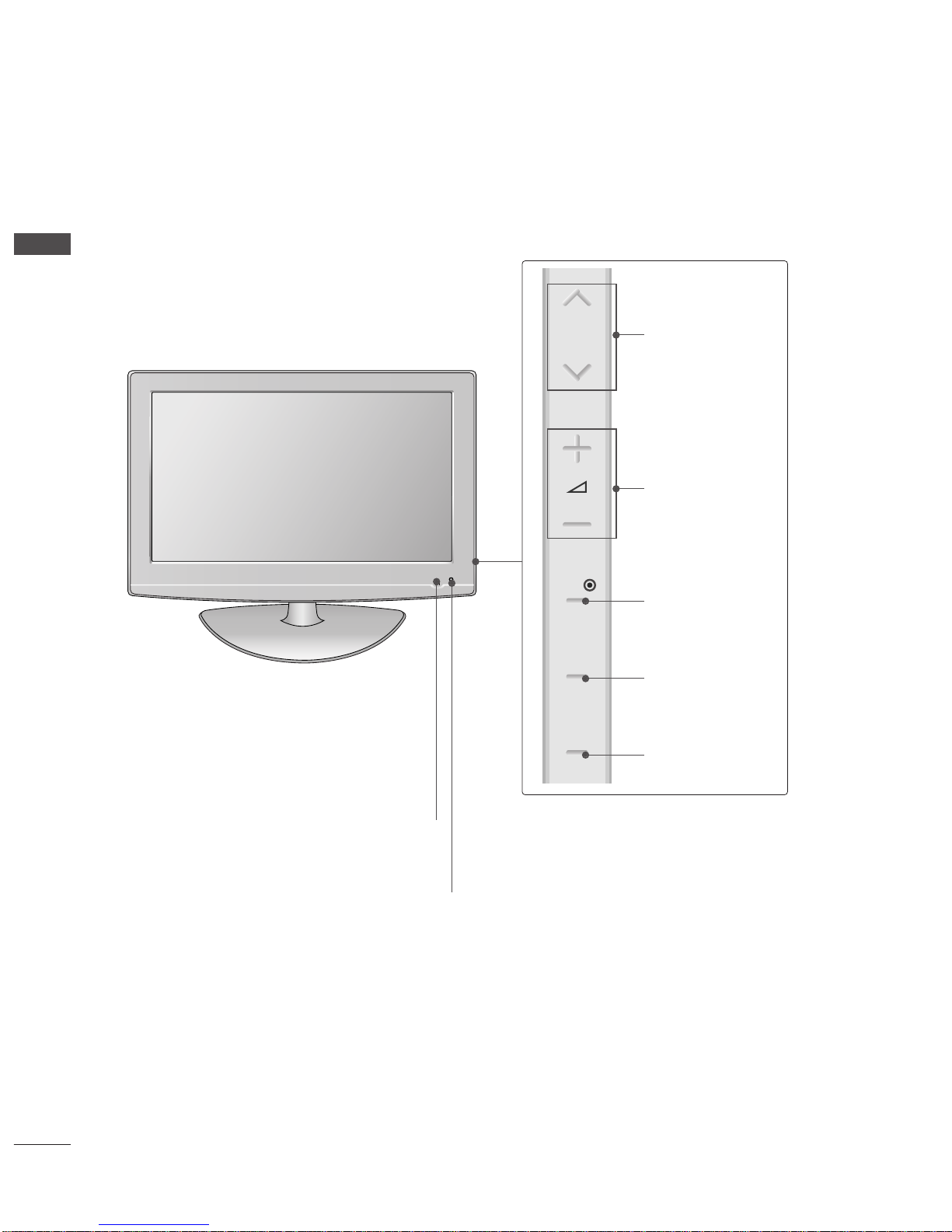
Front Panel Controls . . . . . . . . . . . . . . . . . . . . . . . . 4
Back Panel Information . . . . . . . . . . . . . . . . . . . . . . 5
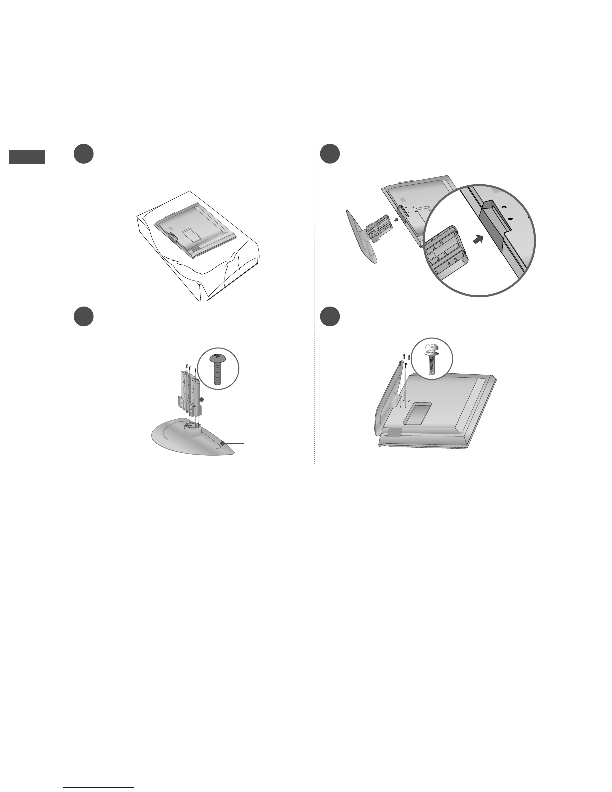
Stand installation . . . . . . . . . . . . . . . . . . . . . . . . . . . . 6
Please set it up carefully so the product
does not fall over . . . . . . . . . . . . . . . . . . . . . . . . . . . 7
Back Cover for Wire Arrangement . . . . . . . . . . . . . . 8
Desktop Pedestal Installation . . . . . . . . . . . . . . . . . . 9
Wall Mount: Horizontal installation . . . . . . . . . . . . . 9
Antenna Connection . . . . . . . . . . . . . . . . . . . . . . . . 10
EXTERNAL EQUIPMENT SETUP
HD Receiver Setup . . . . . . . . . . . . . . . . . . . . . . . . 11
DVD Setup . . . . . . . . . . . . . . . . . . . . . . . . . . . . . . . . 12
VCR Setup . . . . . . . . . . . . . . . . . . . . . . . . . . . . . . . . 15
Other A/V Source Setup . . . . . . . . . . . . . . . . . . . . . 17
External Stereo Aetup . . . . . . . . . . . . . . . . . . . . . . . 17
USB In Setup . . . . . . . . . . . . . . . . . . . . . . . . . . . . . . 18
Digital audio out SETUP . . . . . . . . . . . . . . . . . . . . . 18
PC Setup . . . . . . . . . . . . . . . . . . . . . . . . . . . . . . . . . 19
- Screen Setup for PC Mode . . . . . . . . . . . . . . . 22
WATCHING TV / PROGRAMME CONTROL
Remote Control Key Functions . . . . . . . . . . . . . . . . 25
Turning on the TV . . . . . . . . . . . . . . . . . . . . . . . . . . 27
Programme Selection . . . . . . . . . . . . . . . . . . . . . . . 27
Volume Adjustment . . . . . . . . . . . . . . . . . . . . . . . . . 27
On-Screen Menus Selection and Adjustment . . . . 28
Auto Programme Tuning . . . . . . . . . . . . . . . . . . . . . 29
Manual Programme Tuning (In Digital Mode) . . . . 30
Manual Programme Tuning (In Analogue Mode) . . 31
Programme Edit . . . . . . . . . . . . . . . . . . . . . . . . . . . . 33
Booster . . . . . . . . . . . . . . . . . . . . . . . . . . . . . . . . . . 36
USB Software Upgrade . . . . . . . . . . . . . . . . . . . . . . 37
Selecting the Programme Table . . . . . . . . . . . . . . 38
Key Lock . . . . . . . . . . . . . . . . . . . . . . . . . . . . . . . . . 39
SIMPLINK . . . . . . . . . . . . . . . . . . . . . . . . . . . . . . . . 40
Input Label . . . . . . . . . . . . . . . . . . . . . . . . . . . . . . . 42
AV Mode . . . . . . . . . . . . . . . . . . . . . . . . . . . . . . . . . 43
TIME MACHINE
TimeShift Mode (Pause & Replay of Live TV) . . . 44
Timeshift Initialization . . . . . . . . . . . . . . . . . . . . . . 47
Instant Recording . . . . . . . . . . . . . . . . . . . . . . . . . 48
Manual Record . . . . . . . . . . . . . . . . . . . . . . . . . . . . 50
Schedule List . . . . . . . . . . . . . . . . . . . . . . . . . . . . . 51
Record Quality . . . . . . . . . . . . . . . . . . . . . . . . . . . . 52
To use the USB device . . . . . . . . . . . . . . . . . . . . . 53
Recorded TV Programme List . . . . . . . . . . . . . . . . 54
Photo List . . . . . . . . . . . . . . . . . . . . . . . . . . . . . . . . 57
Music List . . . . . . . . . . . . . . . . . . . . . . . . . . . . . . . . 61
EPG (ELECTRONIC PROGRAMME
GUIDE) (IN DIGITAL MODE)
Switch on/off EPG . . . . . . . . . . . . . . . . . . . . . . . . . 64
Select Programme . . . . . . . . . . . . . . . . . . . . . . . . . . 64
Button Function in NOW/NEXT Guide Mode . . . . . 65
Button Function in 8 Day Guide Mode . . . . . . . . . . 65
Button Function in Date Change Mode . . . . . . . . . . 65
Button Function in Detailed Information Menu . . . . 66
Button Function in Schedule List Mode . . . . . . . . . . 66

3
CONTENTS
PICTURE CONTROL
Watching PIP(Picture-in-Picture) . . . . . . . . . . . . . 67
Picture Size (Aspect Ratio) Control . . . . . . . . . . . . 69
Preset Picture Settings
- Picture Mode-Preset . . . . . . . . . . . . . . . . . . . . 71
-
Auto Colour Tone Control (Warm/Medium/Cool)
. . . . 72
Manual Picture Adjustment
- Picture Mode-User option . . . . . . . . . . . . . . . . 73
- Picture Mode-Expert Control . . . . . . . . . . . . . 74
Picture Improvement Technology . . . . . . . . . . . . . . . . . 75
Advanced - Real Cinema . . . . . . . . . . . . . . . . . . . . . 76
Advanced - Black(Darkness) Level . . . . . . . . . . . . . 77
Eye Care . . . . . . . . . . . . . . . . . . . . . . . . . . . . . . . . . 78
Picture Reset . . . . . . . . . . . . . . . . . . . . . . . . . . . . . . 79
SOUND & LANGUAGE CONTROL
Auto Volume Leveler . . . . . . . . . . . . . . . . . . . . . . . . 80
Preset Sound Settings - Sound Mode . . . . . . . . . . 81
Sound Setting Adjustment - User Mode . . . . . . . . . . 82
SRS TruSurround XT . . . . . . . . . . . . . . . . . . . . . . . . . . . 83
Clear Voice . . . . . . . . . . . . . . . . . . . . . . . . . . . . . . . . . . . 84
Balance . . . . . . . . . . . . . . . . . . . . . . . . . . . . . . . . . . 85
TV Speakers On/ Off Setup . . . . . . . . . . . . . . . . . 86
Selecting Digital Audio Out . . . . . . . . . . . . . . . . . 87
Audio Reset . . . . . . . . . . . . . . . . . . . . . . . . . . . . . . . 88
I/II
-
Stereo/Dual Reception (In Analogue Mode Only)
. . . . 89
-
NICAM Reception (In Analogue Mode Only) . . . . . . .
90
- Speaker Sound Output Selection . . . . . . . . . . 90
On-Screen Menu Language
. . . . . . . . . . . . . . . . . . . . . 91
Audio Language selection (In Digital Mode only) . 92
TIME SETTING
Clock Setup . . . . . . . . . . . . . . . . . . . . . . . . . . . . . . . 93
Auto On/ Off Timer Setting . . . . . . . . . . . . . . . . . . 94
Auto Shut-off Setting . . . . . . . . . . . . . . . . . . . . . . . 95
Sleep Timer Setting . . . . . . . . . . . . . . . . . . . . . . . . . 96
APPENDIX
Initializing (Reset to original factory setting) . . . . . 97
Troubleshooting . . . . . . . . . . . . . . . . . . . . . . . . . . . 98
Maintenance . . . . . . . . . . . . . . . . . . . . . . . . . . . . . . 99
Product Specifications . . . . . . . . . . . . . . . . . . . . . 101
Programming the Remote Control . . . . . . . . . . . . 102
Programming Code . . . . . . . . . . . . . . . . . . . . . . . . 103
IR Codes . . . . . . . . . . . . . . . . . . . . . . . . . . . . . . . . 104

4
PREPARATION
PREPARATION
FRONT PANEL CONTROLS
■
Image shown may differ from your TV.
■
If your TV has a protection film attached, remove the film and then wipe the TV with a polishing cloth.
Intelligent Sensor
Adjusts picture according to the surrounding
conditions.
POWER
Remote Control Sensor
Power/Standby Indicator
• illuminates red in standby mode.
• illuminates blue when the TV is switched on.
Note: You can adjust PPoowweerrIInnddiiccaattoorrin
the OPTION menu.
OK
MENU
INPUT
P
PROGRAMME
VOLUME
OK
MENU
INPUT

5
PREPARATION
ANTENNA /
CABLE IN
DIGITAL AUDIO
OUT OPTICAL
S-VIDEO
VIDEO
RS-232C IN
(CONTROL & SERVICE)
RGB(PC)
AUDIO
(RGB/DVI)
RGB IN
AV IN 1
HDMI/DVI IN
2
1
AUDIO OUT
AUDIO
VIDEO
COMPONENT IN
2
1
L/MONO
R
AUDIOAUDIO
AV IN 2
L/MONO
R
AUDIO
HDMI IN 3 USB IN
VIDEO
Antenna Input
Connect RF antenna to this jack.
RS-232C IN (CONTROL & SERVICE) PORT
Connect to the RS-232C port on a PC.
Audio Out
Connect an external amplifier or add a subwoofer
to your surround sound system.
RGB IN (PC)
Connect the output from a PC.
AUDIO IN (RGB/DVI)
Connect the audio from a PC or DTV.
Power Cord Socket
This TV operates on an AC power. The voltage is
indicated on the Specifications page. Never
attempt to operate the TV on DC power.
DIGITAL AUDIO OUT OPTICAL
Connect digital audio from various types of
equipment.
Note: In standby mode, these ports do not work.
AV (Audio/Video) IN 1/2
Connect audio/video output from an external
device to these jacks.
S-VIDEO
Connect S-Video out from an S-VIDEO device.
Component Input 1/2
Connect a component video/audio device to
these jacks.
HDMI IN 1/2/3
Connect a HDMI signal to HDMI IN. Or DVI
(VIDEO) signal to HDMI/DVI port with DVI to
HDMI cable.
USB Input
1
2
3
4
5
6
7
8
9
10
L/MONO
R
AUDIO
AV IN 2
L/MONO
R
AUDIO
AUDIO
HDMI IN 3
HDMI IN 3
USB IN
USB IN
VIDEO
VIDEO
7 8 96
10
9
7
1 2 3 4 5
BACK PANEL INFORMATION
A
Image shown may differ from your TV.

6
PREPARATION
1 3
4
Carefully place the TV screen side down on a
cushioned surface to protect the screen from
damage.
2Assemble the parts of the SSttaannddBBooddyywith
the CCoovveerrBBaasseeof the TV.
Assemble the TV as shown.
Fix the 4 bolts securely using the holes in the
back of the TV.
Stand Body
Cover Base
STAND INSTALLATION
(
42LG70ED only
)
PREPARATION

7
PREPARATION
PLEASE SET IT UP CAREFULLY SO THE PRODUCT DOES NOT
FALL OVER.
■You should purchase necessary components to fix the TV to the wall on the market.
■Position the TV close to the wall to avoid the possibility of it falling when pushed.
■The instructions shown below are a safer way to set up the TV, which is to fix it to the wall, avoiding the
possibility of it falling forwards if pulled. This will prevent the TV from falling forward and causing injury. This
will also prevent the TV from damage. Ensure that children do not climb or hang from the TV.
NOTE
!
G When moving the TV undo the cords first.
G Use a platform or cabinet strong and large enough to support the size and weight of the TV.
G To use the TV safely make sure that the height of the bracket on the wall and on the TV is the same.
3
1
2
Use the eye-bolts or TV brackets/bolts to fix the TV to the wall as shown in the picture.
(If your TV has bolts in the eyebolts, loosen these bolts.)
* Insert the eye-bolts or TV brackets/bolts and tighten them securely in the upper holes.
Secure the wall brackets with the bolts on the wall. Match the height of the bracket that is mounted on the
wall.
3Use a sturdy rope to tie the TV. It is safer to tie the rope so it becomes horizontal between the wall and the
TV.
2
1
2
1

8
PREPARATION
PREPARATION
BACK COVER FOR WIRE ARRANGEMENT
Connect the cables as necessary.
To connect additional equipment, see the
External Equipment Setup section of the
manual.
1
Open the CCAABBLLEEMMAANNAAGGEEMMEENNTTCCLLIIPPas
shown and manage the cables.
2
CABLE MANAGEMENT CLIP
Fit the CCAABBLLEEMMAANNAAGGEEMMEENNTTCCLLIIPPas
shown.
3

9
PREPARATION
DESKTOP PEDESTAL INSTALLATION
R
For adequate ventilation allow a clearance of 4” (10cm) all around the TV.
EARTHING
Ensure that you connect the earth wire to prevent possible
electric shock. If grounding methods are not possible, have a
qualified electrician install a separate circuit breaker.
Do not try to earth the TV by connecting it to telephone
wires, lightening rods or gas pipes.
Power Supply
Circuit
breaker
■The TV can be installed in various ways such as on a wall, or on a desktop etc.
■The TV is designed to be mounted horizontally.
4 inches
4 inches 4 inches 4 inches
WALL MOUNT: HORIZONTAL INSTALLATION
For adequate ventilation allow a clearance of 4” (10cm) all around the TV. Detailed installation
instructions are available from your dealer, see the optional Tilt Wall Mounting Bracket Installation
and Setup Guide.
4 inches
4 inches
4 inches 4 inches
4 inches
You can remove the stand before installing the TV on a wall mount
by performing the previous stand instructions in reverse. After
removing the stand, install the included pprrootteeccttiioonnccoovveerrover
the hole for the stand.
Insert the PPRROOTTEECCTTIIOONNCCOOVVEERRinto the TV until clicking sound.
Protection cover

10
PREPARATION
PREPARATION
AV 1 AV 2
ANTENNA IN
■For optimum picture quality, adjust antenna direction.
■An antenna cable and converter are not supplied.
■To prevent damage do not connect to the mains outlet until all connections are made between the devices.
Multi-family Dwellings/Apartments
(Connect to wall antenna socket)
Single-family Dwellings /Houses
(Connect to wall jack for outdoor antenna)
Outdoor
Antenna
(VHF, UHF)
Wall
Antenna
Socket
RF Coaxial Wire (75 ohm)
ANTENNA CONNECTION
Antenna
UHF
Signal
Amplifier
VHF
■In poor signal areas, to achieve better picture quality it may be necessary to install a signal amplifier to the
antenna as shown above.
■If signal needs to be split for two TVs,use an antenna signal splitter for connection.
AV IN 3
L/ MONO
R
AUDIO
VIDEO
S-VIDEO
HDMI IN
12
VARIABLE
AUDIO OUT
RGB IN
COMPONENT IN
AUDIO
VIDEO
AV 1 AV 2
ANTENNA
IN
AV 1 AV 2
ANTENNA IN

11
EXTERNAL EQUIPMENT SETUP
EXTERNAL EQIPMENT SETUP
Connect the video outputs (Y, PB, PR)of the digital set
top box to the CCOOMMPPOONNEENNTTIINNVVIIDDEEOOjacks on the TV.
Connect the audio output of the digital set-top box to
the CCOOMMPPOONNEENNTTIINNAAUUDDIIOOjacks on the TV.
Turn on the digital set-top box.
(Refer to the owner’s manual for the digital set-top box.)
Select CCOOMMPPOONNEENNTTinput source using the IINNPPUUTT
button on the remote control.
2
3
4
1
HD RECEIVER SETUP
■To avoid damaging any equipment, never plug in any power cords until you have finished connecting all equipment.
Connecting with a component cable
L/MONO
R
AUDIO
HDMI
DIO OUT
AUDIO
VIDEO
COMPONENT IN
2
1
L/MONO
R
AUDIOAUDIO
L/MONO
R
AUDIO
12
Signal
480i/576i
480p/576p
720p/1080i
1080 p
Component
Yes
Yes
Yes
Yes
HDMI
No
Yes
Yes
Yes
■This TV can receive Digital RF/Cable signals without an external digital set-top box. However, if you do receive
Digital signals from a digital set-top box or other digital external device, refer to the diagram as shown below.

12
EXTERNAL EQUIPMENT SETUP
EXTERNAL EQIPMENT SETUP
Connect the digital set-top box to HHDDMMII//DDVVIIIINN11
jack on the TV.
Connect the audio output of the digital set-top box to
the AAUUDDIIOO((RRGGBB//DDVVII))jack on the TV.
Turn on the digital set-top box. (Refer to the owner’s
manual for the digital set-top box.)
Select HDMI 1 input source using the IINNPPUUTTbutton
on the remote control.
2
3
4
1
Connecting with a HDMI to DVI cable
RGB(PC)
AUDIO
(RGB/DVI)
RGB IN
HDMI/DVI IN
2
1
O OUT
AUDIO
VIDEO
COMPONENT IN
2
1
L/MONO
R
DIOAUDIO
L/MONO
R
AUDIO
L/MONO
R
AUDIO
AUDIO DVI-PC OUTPUT
12
Connecting a set-top box with an HDMI cable
Connect the HDMI output of the digital set-top box to the
HHDDMMII//DDVVIIIINN11,HHDDMMIIIINN22or HHDDMMIIIINN33jack on
the TV.
Turn on the digital set-top box.
(Refer to the owner’s manual for the digital set-top box.)
Select HDMI1,HDMI2 or HDMI3 input source using the
IINNPPUUTTbutton on the remote control.
2
3
1
L/MONO
R
AUDIO
L/MONO
R
AUDIO
HDMI/DVI IN
2
1
AUDIO
VIDEO
COMPONENT IN
2
1
L/MONO
R
AUDIO
1

13
EXTERNAL EQIPMENT SETUP
DVD SETUP
When connecting with a component cable
HDMI/
DIO OUT
AUDIO
VIDEO
COMPONENT IN
2
1
L/MONO
R
AUDIOAUDIO
L/MONO
R
AUDIO
L/MONO
R
AUDIO
Component Input ports
To achieve better picture quality, connect a DVD player to
the component input ports as shown below.
Component ports on the TV
YPBPR
Video output ports
on DVD player
Y
Y
Y
Y
PB
B-Y
Cb
Pb
PR
R-Y
Cr
Pr
Connect the video outputs (Y, PB, PR)of the DVD to the
CCOOMMPPOONNEENNTTIINNVVIIDDEEOOjacks on the TV.
Connect the audio outputs of the DVD to the
CCOOMMPPOONNEENNTTIINNAAUUDDIIOOjacks on the TV.
Turn on the DVD player, insert a DVD.
Select CCOOMMPPOONNEENNTTinput source using the IINNPPUUTTbutton
on the remote control.
Refer to the DVD player's manual for operating instructions.
2
3
4
5
1
1 2

14
EXTERNAL EQUIPMENT SETUP
EXTERNAL EQIPMENT SETUP
L/MONO
R
AUDIO
HDMI/DVI IN
2
1
AUDIO
VIDEO
COMPONENT IN
2
1
L/MONO
R
AUDIO
L/MONO
R
AUDIO
Connecting the HDMI cable
Connect the HDMI output of the DVD to the
HHDDMMII//DDVVIIIINN11, HHDDMMIIIINN22or HHDDMMIIIINN33jack
on the TV.
Select HDMI1, HDMI2 or HDMI3 input source using
the IINNPPUUTTbutton on the remote control.
Refer to the DVD player's manual for operating instructions.
2
3
1
1
GGThe TV can receive video and audio signals simultaneously
when using a HDMI cable.
GGIf the DVD supports Auto HDMI function, the output
resolution of the source device will be automatically set to
1280x720p.
GGIf the DVD does not support Auto HDMI, you must set the
output resolution appropriately.
To get the best picture quality, adjust the output resolution
of the source device to 1280x720p.
NOTE
!
Connecting with a S-Video cable
L/MONO
R
AUDIO
L/MONO
R
AUDIO
L R
S-VIDEOVIDEO
OUTPUT
SWITCH
ANT IN
ANT OUT
DIGITAL AUDIO
OUT OPTICAL
S-VIDEO
VIDEO
AV IN 1
AUDIO OUT
VID
CO
L/MONO
R
AUDIOAUDIO
Connect the S-VIDEO output of the DVD to the
SS--VVIIDDEEOOinput on the TV.
Connect the audio outputs of the DVD to the AAUUDDIIOO
input jacks on the TV.
Turn on the DVD player, insert a DVD.
Select AV1 input source using the INPUT button on
the remote control.
Refer to the DVD player's manual for operating
instructions.
2
3
4
5
1
12

15
EXTERNAL EQIPMENT SETUP
VCR SETUP
■To avoid picture noise (interference), allow adequate distance between the VCR and TV.
■If 4:3 picture format is used for an extended period the fixed images on the sides of the screen may remain
visible.
ANTENNA /
CABLE IN
DIGITAL AUDIO
OUT OPTICAL
S-VIDEO
VIDEO
RS-232C IN
(CONTROL & SERVICE)
RGB(PC)
AUDIO
(RGB/DVI)
RGB IN
AV IN 1
HDMI/DVI IN
2
1
AUDIO OUT
AUDIO
VIDEO
COMPONENT IN
2
1
L/MONO
R
AUDIOAUDIO
L/MONO
R
AUDIO
L/MONO
R
AUDIO
OUTPUT
SWITCH
ANT IN
R
S-VIDEO VIDEO
ANT OUT L
Wall Jack
Antenna
1
2
When connecting with a RF Cable
Connect the AANNTTOOUUTTsocket of the VCR to the AANNTTEENNNNAA//CCAABBLLEEIINN
socket on the TV.
Connect the antenna cable to the AANNTTIINNsocket of the VCR.
Press the PLAY button on the VCR and match the appropriate channel between
the TV and VCR for viewing.
1
2
3

16
EXTERNAL EQUIPMENT SETUP
EXTERNAL EQIPMENT SETUP
GGIf both S-VIDEO and VIDEO sockets have been connected to
the S-VHS VCR simultaneously, only the S-VIDEO can be
received.
NOTE
!
L/MONO
R
AUDIO
L R
S-VIDEOVIDEO
OUTPUT
SWITCH
ANT IN
ANT OUT
DIGITAL AUDIO
OUT OPTICAL
S-VIDEO
VIDEO
AV IN 1
AUDIO OUT
VID
CO
L/MONO
R
AUDIOAUDIO
L/MONO
R
AUDIO
Connecting with a S-Video cable
Connect the S-VIDEO output of the VCR to the S -
VIDEO input on the TV. The picture quality is improved;
compared to normal composite (RCA cable) input.
Connect the audio outputs of the VCR to the AUDIO
input jacks on the TV.
Insert a video tape into the VCR and press PLAY on the
VCR. (Refer to the VCR owner’s manual.)
Select AV1 input source using the IINNPPUUTTbutton on the
remote control.
2
3
4
1
1 2
Connecting with a RCA cable
L/MONO
R
AUDIO
L/MONO
R
AUDIO
L R
S-VIDEO VIDEO
OUTPUT
SWITCH
ANT IN
ANT OUT
DIGITAL AUDIO
OUT OPTICAL
S-VIDEO
VIDEO
AV IN 1
AUDIO OUT
VIDEO
COM
L/MONOMONO
R
AUDIOAUDIO
Connect the AAUUDDIIOO/VVIIDDEEOOjacks between TV and
VCR. Match the jack colours (Video = yellow, Audio Left
= white, and Audio Right = red)
Insert a video tape into the VCR and press PLAY on
the VCR. (Refer to the VCR owner’s manual.)
Select AV1 input source using the IINNPPUUTTbutton on
the remote control.
If connected to AAVVIINN22socket, select AAVV22input
source.
1
2
3
GGIf you have a mono VCR, connect the audio cable from the
VCR to the AAUUDDIIOOLL//MMOONNOOjack of the TV.
NOTE
!
This manual suits for next models
2
Table of contents
Other LG LCD TV manuals