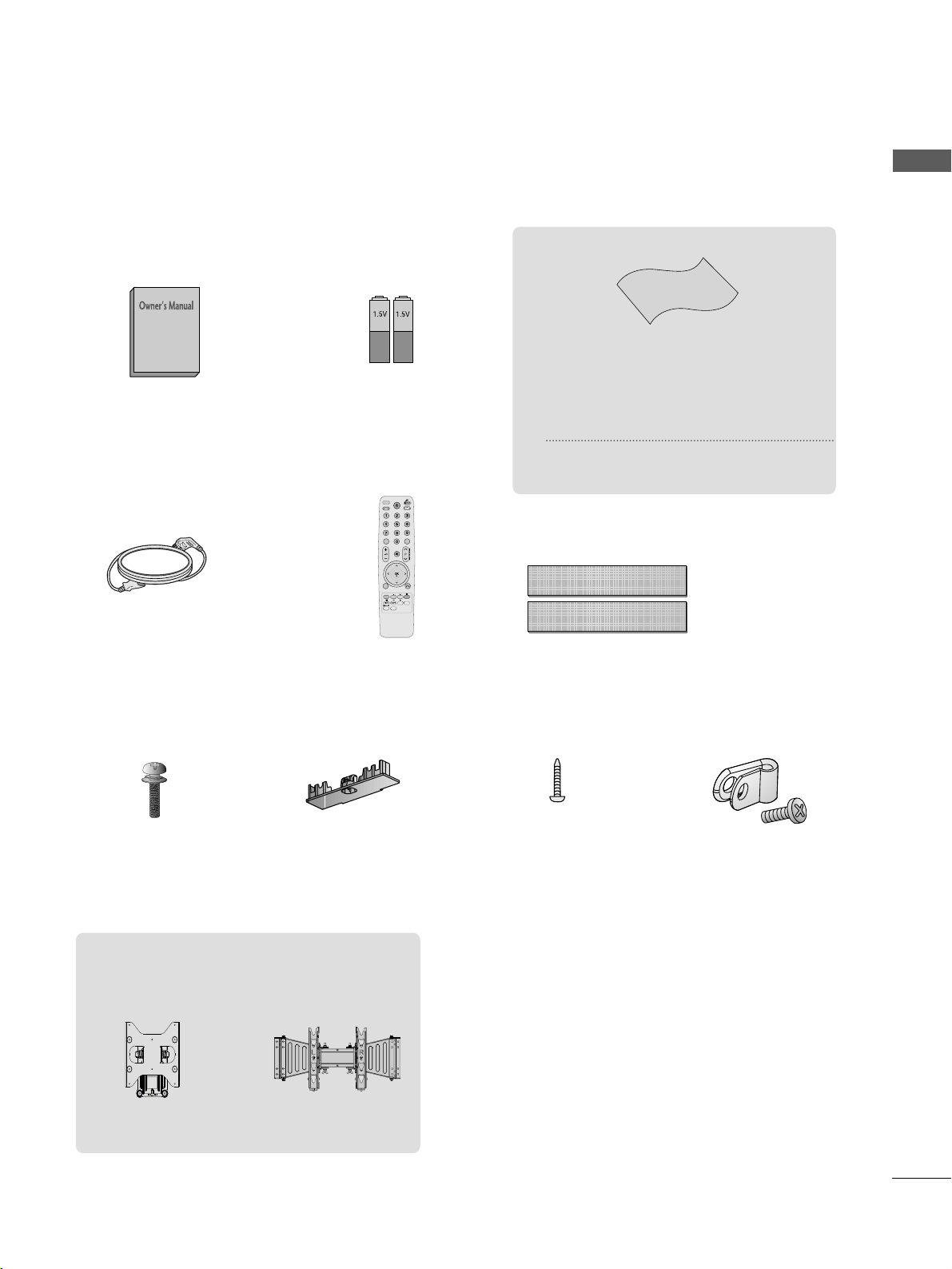
LG 42LH2*** series User manual

www.lg.com
OWNER’S MANUAL
LCD TV
Please read this manual carefully before operating
your set and retain it for future reference.
P/NO: MFL59868613 (1012-REV08)
Printed in Korea

HDMI, the HDMI logo and High-Definition
Multimedia Interface are trademarks or registered
trademarks of HDMI Licensing LLC

1
ACCESSORIES
ACCESSORIES
Ensure that the following accessories are included with your TV
If an accessory is missing, please contact the dealer where you purchased the TV
■
Here shown may be somewhat different from your TV
Owner’s Manual Batteries
Remote ControlPower Cord
Polishing Cloth
Polishing cloth for use on the screen.
his item is not included for all models.
* Lightly wipe any stains or fingerprints on
the surface of the V with the polishing
cloth.
AVMODEVMODE
ENERGYENERGYSASAVINGVING
RETURN
MENU
Q.MENU
MARK
MUTEMUTE
POWERPOWER
LISTLIST
Q.VIEWQ.VIEW
RARATIOTIO
FAV
AVMODE
ENERGYSAVING
MUTE
LIST
Q.VIEW
Bolts for stand assembly
(Refer to p.6)
x 4
Protection cover
(Refer to p.7)
1-screw for stand fixing
(Refer to p.6)
Wall Mounting Bracket(Separate purchase)
RW230
(26/32LH2***)
AW-47LG30M
(32/37/42LH2***)
Protective Bracket and
Bolt for Power Cord
(Refer to p.6)
Do not use excessive force. his may
cause scratching or discolouration.
Dual Lock™
(
his item is not included
for all models.
)
(Refer to P7)

CONTENTS
2
CONTENTS
ACCESSORIES
1
PREPARA ION
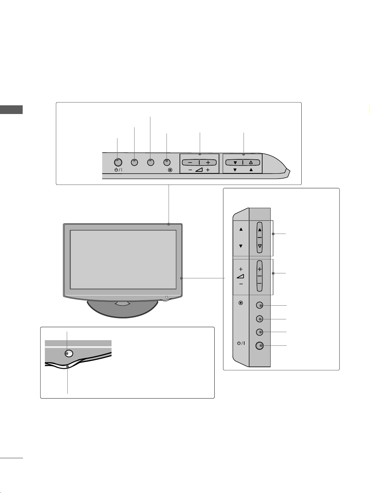
Front Panel Controls 4
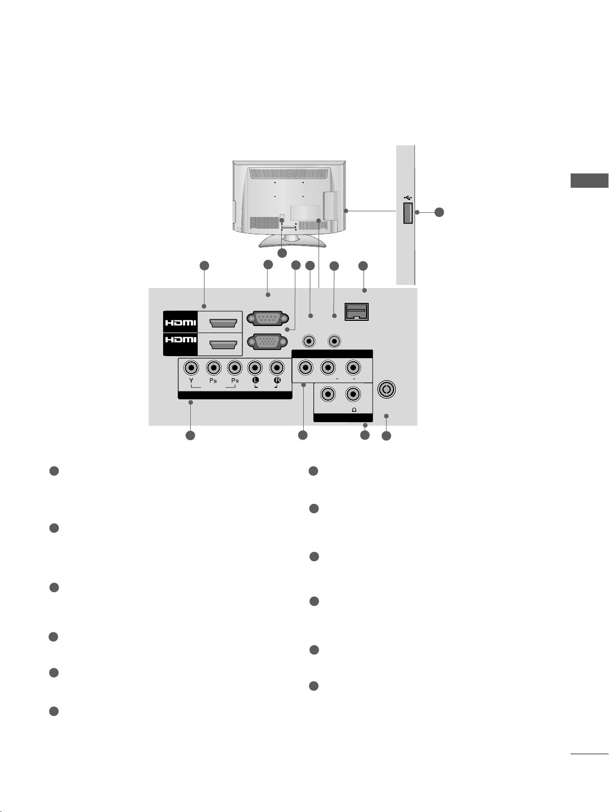
Back Panel Information 5
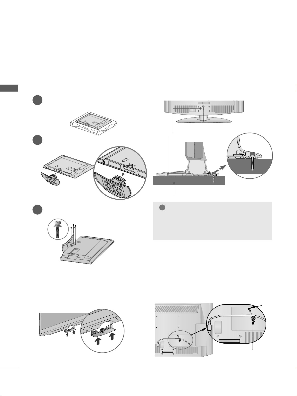
Stand Installation 6
Not Using the desk-type stand 6
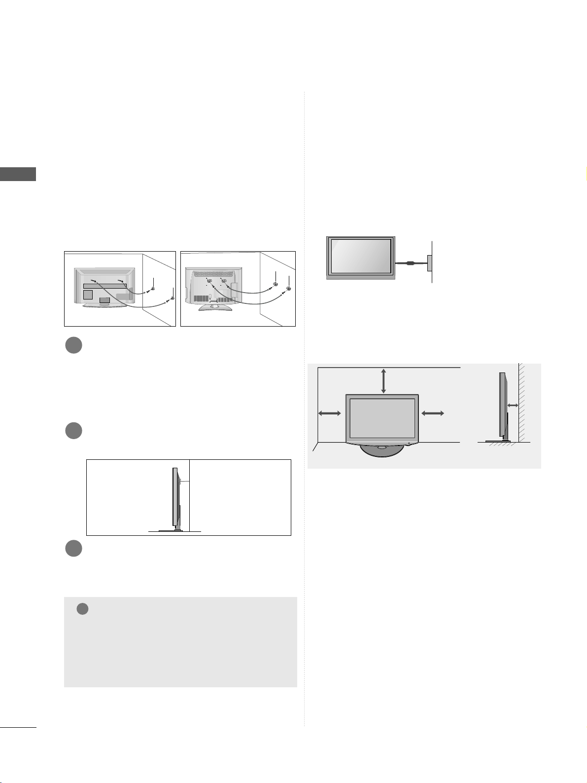
Attaching the TV to a desk 6
How to secure the power cable 6
Back Cover for Wire Arrangement 7
Swivel Stand 7
How to use Dual Lock™ 7
Careful Installation Advice 8
Desktop Pedestal Installation 8
Wall Mount: Horizontal Installation 9
Kensington Security System 9
Antenna Connection 10
EX ERNAL EQUIPMEN SE UP
HD Receiver Setup 11
DVD Setup 14
VCR Setup 16
Other A/V Source Setup 18
USB In Setup 19
Speaker Output Setup 19
PC Setup 20
- Screen Setup for PC Mode 22
WA CHING V / PROGRAMME CON ROL
Remote Control Key Functions 26
Turning on the TV 28
Programme Selection 28
Volume Adjustment 28
Quick Menu 29
On-Screen Menus Selection and Adjustment 30
Auto Programme Tuning 31
Manual Programme Tuning 32
Programme Edit 34
Selecting the Programme List 36
Favourite Programme Setup 37
Input List 38
Input Label 39
40
Key Lock 43
Initializing(Reset to original factory settings) 44
AV Mode 45
O USB A USB DEVICE
When connecting the USB device 46
Photo List 48
Music List 52
Movie List 55
Divx Registration Code 58
Deactivation 59
PIC URE CON ROL
Picture Size (Aspect Ratio) Control 60
Energy Saving 62
Preset Picture Settings
- Picture Mode-Preset 63
Manual Picture Adjustment
- Picture Mode-User option 64
Picture Improvement Technology 65
Expert Picture Control 66
Picture Reset 69
Power Indicator 69
Demo Mode 70
SOUND & LANGUAGE CON ROL
Auto Volume Leveler 71
Preset Sound Settings - Sound Mode 72
Sound Setting Adjustment - User Mode 73
Clear Voice ll 74
Balance 75
Audio Reset 76

CONTENTS
3
I/II
- Stereo/Dual Reception 77
- NICAM Reception 78
- Speaker Sound Output Selection 78
On-Screen Menu Language Selection 79
IME SE ING
Clock Setup 80
Auto On/ Off Timer Setting 81
Sleep Timer Setting 82
ELE EX
Switch on/off 83
SIMPLE Text 83
TOP Text 83
FASTEXT 84
Special Teletext Functions 84
APPENDIX
Troubleshooting 85
Maintenance 87
Product Specifications 88
IR Codes 89
External Control Device Setup 90

PREPARATION
4
PREPARATION
FRONT PANEL CONTROLS
■
Here shown may be somewhat different from your TV
Only 32/37/42LH2***
INPUT MENU
P
OK
PROGRAMME
VOLUME
OK
Only 26LH2***
MENU
POWER
INPUT
INPUT
MENU
OK
P
PROGRAMME
VOLUME
OK
MENU
INPUT
POWER
Remote Control Sensor
Power/Standby Indicator
• Illuminates red in standby mode
• Illuminates blue when the TV is switched on
This is a simplified representation of the front panel

5
PREPARATION
BACK PANEL INFORMATION
■
Here shown may be somewhat different from your TV
L( MONO)
R
AUDIO
VIDEO
VARIABLE AUDIO OUT
ANTENNA IN
L( MONO)
R
AUDIO
VIDEO
VARIABLE AUDIO OUT
ANTENNA
IN
1
AUDIO
VIDEO
L(L(MONO)MONO)
R
AUDIOAUDIO
AV IN
SPEAKER OUT
VIDEOVIDEO
VOLUMEVOLUME
CONTROLCONTROL
STEREO\STEREO\
(8 )(8 )
ANTENNA
IN
RGB IN
(PC)
RS-232C IN
(CONTROL&SERVICE)
AUDIO IN
(RGB/DVI)
RJP
INTERFACE
AUDIO
OUT
1
2
/DVI IN
COMPONENT IN
6
3
24
810
7
Power Cord Socket
This TV operates on an AC power The voltage is
indicated on the Specifications page Never
attempt to operate the TV on DC power
HDMI Input
Connect a HDMI signal to HDMI IN
Or DVI(VIDEO)signal to HDMI/DVI port with DVI
to HDMI cable
RS-232C IN PORT
Connect to the RS-232C port on a PC
This port is used for Service or Hotel mode
RGB Input
Connect the output from a PC
RGB/DVI Audio Input
Connect the audio from a PC
Audio Output
Connect to the Home Theater(or amp)
RJP INTERFACE
Connect control line (RJ45) for RJP(Remote Jack pack)
Component Input
Connect a component video/audio device to these
jacks
Audio/Video Input
Connect audio/video output from an external
device to these jacks
SPEAKER OUTPUT(STEREO)
The phone socket for external speaker is on this
jack
Antenna Input
Connect RF antenna to this jack
USB IN Input
Connect USB storage device to this jack
1
2
3
4
5
6
8
9
10
11
7
5
11
L(MONO)
R
AUDIO
VIDEO
VOLUME
CONTROL
STEREO\
(8 )
ANTENNA
IN
USB IN
12
12
9

6
PREPARATION
PREPARATION
STAND INSTALLATION
■
Here shown may be somewhat different from your TV
When assembling the desk type stand, check whether the
bolt is fully tightened (If not tightened fully, the product
can tilt forward after the product installation ) If you tight-
en the bolt with excessive force, the bolt can deviate from
abrasion of the tightening part of the bolt
1
2
3
Carefully place the TV screen side down on a cushioned
surface to protect the screen from damage
Assemble the TV as shown
Fix the 4 bolts securely using the holes in the
back of the TV
ATTACHING THE TV TO A
DESK
■
Here shown may be somewhat different from your TV
The TV must be attached to desk so it cannot be pulled
in a forward/backward direction, potentially causing
injury or damaging the product Use only an attached
screw
1-Screw (provided as parts of the product)
Desk
Stand
WARNING
!
G To prevent TV from falling over, the TV should be
securely attached to the floor/wall per installation
instructions Tipping, shaking, or rocking the
machine may cause injury
PRO EC IVE BRACKE
Bolt
Secure the power cable with the PRO EC IVE BRACKE and
the bolt as shown It will help prevent the power cable from
being removed by accident
HOW TO SECURE THE
POWER CABLE
■
Here shown may be somewhat different from your TV
When installing the wall-mounted unit, use the pro-
tection cover
NOT USING THE DESK-TYPE
STAND
Insert the PPRROOTTEECCTTIIOONN CCOOVVEERRinto the TV until
clicking sound

7
PREPARATION
BACK COVER FOR WIRE
ARRANGEMENT
■
Here shown may be somewhat different from your TV
Connect the cables as necessary
To connect additional equipment, see the External
Equipment Setup section of the manual
1
Open the CCAABBLLEE MMAANNAAGGEEMMEENNTT CCLLIIPPas
shown and manage the cables
2
CABLE MANAGEMENT CLIP
Fit the CCAABBLLEE MMAANNAAGGEEMMEENNTT CCLLIIPPas shown
3
GGDo not hold the CABLE MANAGEMEN CLIP
when moving the TV
- If the TV is dropped, you may be injured or the
TV may be damaged
NO E
!
HOW TO USE DUAL LOCK™
(This feature is not available for all
models )
Fix the set-top box to the TV and use it when you
want to
After removing the protection paper from the
Dual Lock, stick it to the TV and the set-top
box as shown
Attach the set-top box to the TV by pressing the
Velcro strips together
SWIVEL STAND
■
This feature is not available for all models
■
After installing the TV, you can adjust the TV manually
to the left or right direction by 20 degrees to suit your
viewing position
1
2

8
PREPARATION
PREPARATION
AThe TV can be installed in various ways such as on
a wall, or on a desktop etc
A The TV is designed to be mounted horizontally
Power Supply
Circuit breaker
EAR HING
Ensure that you connect the earth wire to prevent pos-
sible electric shock If grounding methods are not pos-
sible, have a qualified electrician install a separate cir-
cuit breaker
Do not try to earth the TV by connecting it to tele-
phone wires, lightening rods or gas pipes
10 c m
10 c m 10 c m 10 c m
DESKTOP PEDESTAL INSTALLATION
For adequate ventilation allow a clearance of 10cm
all around the TV
CAREFUL INSTALLATION ADVICE
AYou should purchase necessary components to fix the TV
safety and secure to the wall on the market
APosition the TV close to the wall to avoid the possibility
of it falling when pushed
AThe instructions shown below are a safer way to set up
the TV, by fixing it to the wall, avoiding the possibility of
it falling forwards if pulled This will prevent the TV from
falling forward and causing injury This will also prevent
the TV from damage Ensure that children do not climb or
hang from the TV
NO E
!
G When moving the TV undo the cords first
G Use a platform or cabinet strong and large enough to
support the size and weight of the TV
G To use the TV safely make sure that the height of the
bracket on the wall and on the TV is the same
3
1
2
Use the eye-bolts or TV brackets/bolts to fix the prod-
uct to the wall as shown in the picture
(If your TV has bolts in the eyebolts, loosen then
bolts )
* Insert the eye-bolts or TV brackets/bolts and tight-
en them securely in the upper holes
Secure the wall brackets with the bolts on the wall
Match the height of the bracket that is mounted on the
wall
3
Use a sturdy rope to tie the product for alignment It
is safer to tie the rope so it becomes horizontal
between the wall and the product
2
1
2
1

9
PREPARATION
WALL MOUNT: HORIZONTAL
INSTALLATION
AWe recommend the use of a LG Brand wall mounting
bracket when mounting the TV to a wall
AWe recommend that you purchase a wall mounting
bracket which supports VESA standard
ALG recommends that wall mounting be performed
by a qualified professional installer
10 cm
10 c m
10 c m
10 c m
10 c m
NO E
!
G Should Install wall mount on a solid wall perpendicular to
the floor
G Should use a special wall mount, if you want to install it to
ceiling or slanted wall
G The surface that wall mount is to be mounted on should be
of sufficient strength to support the weight of TV set; e g
concrete, natural rock, brick and hollow block
G Installing screw type and length depends on the wall mount
used Further information, refer to the instructions included
with the mount
G LG is not liable for any accidents or damage to property or
TV due to incorrect installation:
- Where a non-compliant VESA wall mount is used
- Incorrect fastening of screws to surface which may cause
TV to fall and cause personal injury
- Not following the recommended Installation method
Model VESA
(A *B) Standard
Screw Quantity
42LH2***
37LH2***
32LH2***
26LH2***
200 * 200
200 * 200
200 * 10 0
200 * 10 0
M6
M6
M4
M4
4
4
4
4
BB
AA
KENSINGTON SECURITY SYSTEM
■
This feature is not available for all models
■
Here shown may be somewhat different from your TV
The TV is equipped with a Kensington Security System
connector on the back panel Connect the Kensington
Security System cable as shown below
For the detailed installation and use of the Kensington
Security System, refer to the user’s guide provided
with the Kensington Security System
For further information, contact http://www kensing-
ton com, the internet homepage of the Kensington
company Kensington sells security systems for expen-
sive electronic equipment such as notebook PCs and
LCD projectors
NOTE
- The Kensington Security System is an optional accessory
NOTES
a If the TV feels cold to the touch, there may be a
small “flicker” when when it is turned on
This is normal, there is nothing wrong with TV
b Some minute dot defects may be visible on the
screen, appearing as tiny red, green, or blue spots
However, they have no adverse effect on the moni-
tor's performance
c Avoid touching the LCD screen or holding your finger(s)
against it for long periods of time
Doing so may produce some temporary distortion
effects on the screen

L(MONO)
R
AUDIO
VIDEO
VARIABLE AUDIO OUT
ANTENNA
IN
L(MONO)
R
AUDIO
VIDEO
VARIABLE AUDIO OUT
ANTENNA
IN
L( MONO)
R
AUDIO
VIDEO
VARIABLE AUDIO OUT
ANTENNA IN
L( MONO)
R
AUDIO
VIDEO
VARIABLE AUDIO OUT
ANTENNA
IN
10
PREPARATION
PREPARATION
ANTENNA CONNECTION
■For optimum picture quality, adjust antenna direction
■An antenna cable and converter are not supplied
■To prevent damage do not connect to the mains outlet until all connections are made between the devices
Multi-family Dwellings/Apartments
(Connect to wall antenna socket)
Single-family Dwellings /Houses
(Connect to wall jack for outdoor antenna)
Outdoor
Antenna
(VHF, UHF)
Wall
Antenna
Socket
RF Coaxial Wire (75 Ω)
Antenna
UHF
Signal
Amplifier
VHF
■In poor signal areas, to achieve better picture quality it may be necessary to install a signal amplifier to the
antenna as shown above
■If signal needs to be split for two TVs, use an antenna signal splitter for connection

11
EXTERNAL EQUIPMENT SETUP
1
/DVI IN
2
COMPONENT IN
AUDIO
VIDEO
RGB IN
(PC)
A
S
VIDEO
C
AUDIO IN
(RGB/DVI)
HD RECEIVER SETUP
■To avoid damaging any equipment, never plug in any power cords until you have finished connecting all equipment
■
Here shown may be somewhat different from your TV
Connecting with a component cable
12
Signal
480i/576i
480p/576p
720p/1080i
108 0 p
Component
O
O
O
O
(50 / 60 Hz only)
HDMI
X
O
O
O
(24 Hz / 30 Hz / 50 Hz / 60 Hz)
Connect the video outputs (Y, PB, PR)of the digital set
top box to the CCOOMMPPOONNEENNTT IINN VVIIDDEEOOjacks on the
TV
Connect the audio output of the digital set-top box to
the CCOOMMPPOONNEENNTT IINN AAUUDDIIOOjacks on the TV
Turn on the digital set-top box
(Refer to the owner’s manual for the digital set-top box )
Select CCoommppoonneennttinput source using the IINNPPUUTT
button on the remote control
2
3
4
1

12
EXTERNAL EQUIPMENT SETUP
Connecting a set-top box with an HDMI cable
Connect the digital set-top box to HHDDMMII//DDVVII IINN 11
or HHDDMMII22jack on the TV
Turn on the digital set-top box
(Refer to the owner’s manual for the digital set-top
box )
Select HHDDMMII11 or HHDDMMII22input source using the
IINNPPUUTTbutton on the remote control
2
3
1
GGCheck that your HDMI cable is High Speed HDMI cable
If the HDMI cables are not High Speed HDMI cable, flick-
ering or no screen display can result Please use the High
Speed HDMI cable
GGWe recommed less than 10m for HDMI cable, and recom-
mend to use amplifier or repeater for more than that
NOTE
!
COMPONENT IN
VIDEO
LYP
B
P
R
R
AUDIO
RGB IN
(PC)
1
2
/DVI IN
RS-232C IN
(CONTROL&SERVICE)
VIDEO
AUDIO I
(RGB/DV
1

13
EXTERNAL EQUIPMENT SETUP
Connecting with an HDMI to DVI cable
Connect the digital set-top box to HHDDMMII//DDVVII IINN 11 jack on the TV
Connect the audio output of the digital set-top box to the AAUUDDIIOO IINN ((RRGGBB//DDVVII)) jack on the
TV
Turn on the digital set-top box (Refer to the owner’s manual for the digital set-top box )
Select HHDDMMII11input source using the IINNPPUUTTbutton on the remote control
2
3
4
1
COMPONENT IN
VIDEO
LYP
B
P
R
R
AUDIO
RGB IN
(PC)
1
/DVI IN
2
L(MONO)
R
AUDIO
AV IN
SPEAKER OUT
VIDEO
VOLUME
CONTROL
STEREO\
(8 )
ANTENNA
IN
AUDIO IN
(RGB/DVI)
RJP
INTERFACE
AUDIO
OUT
RS-232C IN
(CONTROL&SERVICE)
12

14
EXTERNAL EQUIPMENT SETUP
DVD SETUP
Connecting with a component cable
1
/DVI IN
2
COMPONENT IN
AUDIO
VIDEO
RGB IN
(PC)
A
S
VIDEO
V
C
AUDIO IN
(RGB/DVI)
RS-232C IN
(CONTROL&SERVICE)
Component Input ports
To achieve better picture quality, connect a DVD player to the component input ports as shown below
Component ports on the TV
YPBPR
Video output ports
on DVD player
Y
Y
Y
Y
PB
B-Y
Cb
Pb
PR
R-Y
Cr
Pr
1 2
Connect the video outputs (Y, PB, PR)of the DVD to the
CCOOMMPPOONNEENNTT IINN VVIIDDEEOOjacks on the TV
Connect the audio outputs of the DVD to the
CCOOMMPPOONNEENNTT IINN AAUUDDIIOOjacks on the TV
Turn on the DVD player, insert a DVD
Select CCoommppoonneenntt input source using the IINNPPUUTT
button on the remote control
Refer to the DVD player's manual for operating instructions
2
3
4
5
1

15
EXTERNAL EQUIPMENT SETUP
Connecting the HDMI cable
Connect the HDMI output of the DVD to the
HHDDMMII//DDVVII IINN 11 or HHDDMMII22jack on the TV.
Select HHDDMMII11 or HHDDMMII22input source using the
IINNUUTTbutton on the remote control.
Refer to the DVD player's manual for operating instructions.
2
3
1
GGThe TV can receive video and audio signals simultaneously when using a HDMI cable.
GGIf the DVD does not support Auto HDMI, you must set the output resolution appropriately.
GGCheck that your HDMI cable is High Speed HDMI Cable. If the HDMI cables are not High Speed HDMI
cable, flickering or no screen display can result. lease use the High Speed HDMI cable.
GGWe recommed less than 10m for HDMI cable, and recommend to use amplifier or repeater for more than
that.
NOTE
!
COMPONENT IN
VIDEO
LYP
B
P
R
R
AUDIO
RGB IN
(PC)
1
2
/DVI IN
RS-232C IN
(CONTROL&SERVICE)
VIDEO
AUDIO
(RGB/D
1

16
EXTERNAL EQUIPMENT SETUP
VCR SETUP
■To avoid picture noise (interference), allow adequate distance between the VCR and TV
ANTENNA
IN
OUTPUT
SWITCH
ANT IN
R
S-VIDEO VIDEO
ANT OUT L
COMPONENT IN
VIDEO
LYP
B
P
R
R
AUDIO
RGB IN
(PC)
L(MONO)
R
AUDIO
AV IN
SPEAKER OUT
VIDEO
VOLUME
CONTROL
STEREO\
(8 )
AUDIO IN
(RGB/DVI)
RJP
INTERFACE
AUDIO
OUT
1
/DVI IN
2
RS-232C IN
(CONTROL&SERVICE)
Wall Jack
Antenna
1
2
Connecting with a RF Cable
Connect the AANNTT OOUUTTsocket of the VCR to the AANNTTEENNNNAA IINNsocket on the TV
Connect the antenna cable to the AANNTT IINNsocket of the VCR
Press the PPLLAAYYbutton on the VCR and match the appropriate channel between the TV and VCR for viewing
2
3
1

17
EXTERNAL EQUIPMENT SETUP
VIDEO
AUDIO
/MONO
ENT IN
L R
AUDIO
RGB IN
(PC)
AV IN
SPEAKER OUT
VOLUME
CONTROL
STEREO\
(8 )
ANTENNA
IN
AUDIO IN
(RGB/DVI)
AUDIO
OUT
LR
S-VIDEO VIDEO
OUTPUT
SWITCH
ANT IN
ANT OUT
Connecting with a RCA cable
Connect the AAUUDDIIOO/VVIIDDEEOOjacks between TV and
VCR Match the jack colours (Video = yellow, Audio Left
= white, and Audio Right = red)
Insert a video tape into the VCR and press PLAY on the
VCR (Refer to the VCR owner’s manual )
Select AAVVinput source using the IINNPPUUTTbutton on the
remote control
1
2
3
GGIf you have a mono VCR, connect the audio cable from the
VCR to the AAUUDDIIOO LL//MMOONNOOjack of the TV
NO E
!
1

18
EXTERNAL EQUIPMENT SETUP
OTHER A/V SOURCE SETUP
Connect the AAUUDDIIOO/VVIIDDEEOOjacks between TV and external equipment Match the jack colours
(Video = yellow, Audio Left = white, and Audio Right = red)
Select AAVVinput source with using the IINNPPUUTTbutton on the remote control
Operate the corresponding external equipment
Refer to external equipment operating guide
1
2
3
COMPONENT IN
VIDEO
LYP
B
P
R
R
AUDIO
VIDEO
AUDIO
/MONO
IN
RGB IN
(PC)
AV IN
SPEAKER OUT
VOLUME
CONTROL
STEREO\
(8 )
ANTENNA
IN
AUDIO IN
(RGB/DVI)
RJP
INTERFACE
AUDIO
OUT
L R
VIDEO
1
/DVI IN
2
RS-232C IN
(CONTROL&SERVICE)
Camcorder
Video Game Set
1
This manual suits for next models
3
Table of contents
Other LG LCD TV manuals

LG
LG 26LZ5RV User manual

LG
LG 47LB1DA User manual

LG
LG LH9000 Series Assembly instructions

LG
LG 55LD520C User manual

LG
LG 32LD650H User manual

LG
LG 32LG5010 User manual

LG
LG 47LM580S User manual

LG
LG 47LD450 User manual

LG
LG 323DCH - 32In Wide Lcd Hdtv Spk 1366X768 Hospital... User manual

LG
LG M2432D User manual