LG DU-30LZ30 User manual

LCD
Color Television
OWNER’S MANUAL
Please read this manual carefully before operating your set.
Retain it for future reference.
Record model number and serial number of the set.
See the label attached on the back cover and quote this
information to your dealer when you require service.
MODELS: DU-30LZ30
DU-42LZ30
LG Electronics U.S.A. , Inc.

2
Warning
WARNING:
TO REDUCE THE RISK OF ELECTRIC SHOCK DO NOT REMOVE COVER (OR BACK). NO USER
SERVICEABLE PARTS INSIDE. REFER TO QUALIFIED SERVICE PERSONNEL.
The lightning flash with arrowhead symbol, within an equilateral triangle, is intended to alert the user to
the presence of uninsulated “dangerous voltage” within the product’s enclosure that may be of sufficient
magnitude to constitute a risk of electric shock to persons.
The exclamation point within an equilateral triangle is intended to alert the user to the presence of impor-
tant operating and maintenance (servicing) instructions in the literature accompanying the appliance.
WARNING:
TO PREVENT FIRE OR SHOCK HAZARDS, DO NOT EXPOSE THIS PRODUCT TO RAIN OR MOISTURE.
POWER CORD POLARIZATION:
CAUTION: TO PREVENT ELECTRIC SHOCK, MATCH WIDE BLADE OF PLUG TO WIDE SLOT, FULLY INSERT.
NOTE TO CABLE/TV INSTALLER:
This reminder is provided to call the CATV system installer’s attention to Article 820-40 of the National Electric Code
(U.S.A.). The code provides guidelines for proper grounding and, in particular, specifies that the cable ground shall be
connected to the grounding system of the building, as close to the point of the cable entry as practical.
REGULATORY INFORMATION:
This equipment has been tested and found to comply with the limits for a Class B digital device, pursuant to Part 15 of
the FCC Rules. These limits are designed to provide reasonable protection against harmful interference when the equip-
ment is operated in a residential installation. This equipment generates, uses and can radiate radio frequency energy
and, if not installed and used in accordance with the instruction manual, may cause harmful interference to radio com-
munications. However, there is no guarantee that interference will not occur in a particular installation. If this equipment
does cause harmful interference to radio or television reception, which can be determined by turning the equipment off
and on, the user is encouraged to try to correct the interference by one or more of the following measures:
• Reorient or relocate the receiving antenna.
• Increase the separation between the equipment and receiver.
• Connect the equipment into an outlet on a circuit different from that to which the receiver is connected.
• Consult the dealer or an experienced radio/TV technician for help.
Any changes or modifications not expressly approved by the party responsible for compliance could void the user’s
authority to operate the equipment.
COMPLIANCE:
The responsible party for this product’s compliance is:
LG Electronics.
CAUTION:
Do not attempt to modify this product in any way without written authorization from LG Electronics. Unauthorized mod-
ification could void the user’s authority to operate this product.
The responsible party for this product’s compliance is :
LG Electronics U.S.A., Inc.
1000 Sylvan Avenue, Englewood Cliffs, NJ 07632
1-201-816-2000
http://www.lgusa.com
WARNING
RISK OF ELECTRIC SHOCK
DO NOT OPEN
W
Warning
arning

3
Safety Instructions
Important safeguards for you and your new product
Your product has been manufactured and tested with your safety in mind. However, improper use can result in electrical
shock or fire hazards. To avoid defeating the safeguards that have been built into your new product, please read and observe
the following safety points when installing and using your new product, and save them for future reference.
Observing the simple precautions discussed in this manual can help you get many years of enjoyment and safe operation
that are built into your new product.
This product complies with all applicable U.S. Federal safety requirements, and those of the Canadian StandardsAssociation.
1. Read Instructions
All the safety and operating instructions should be read
before the product is operated.
2. Follow Instructions
All operating and use instructions should be followed.
3. Retain Instructions
The safety and operating instructions should be retained for
future reference.
4. Heed Warnings
All warnings on the product and in the operating instructions
should be adhered to.
5. Cleaning
Unplug this product from the wall outlet before cleaning. Do
not use liquid cleaners or aerosol cleaners. Use a damp
cloth for cleaning.
6. Water and Moisture
Do not use this product near water, for example, near a bath
tub, wash bowl, kitchen sink, or laundry tub, in a wet base-
ment, or near a swimming pool.
7. Accessories, Carts, and Stands
Do not place this product on a slippery or tilted surface, or on
an unstable cart, stand, tripod, bracket, or table. The product
may slide or fall, causing serious injury to a child or adult,
and serious damage to the product. Use only with a cart,
stand, tripod, bracket, or table recommended by the manu-
facturer, or sold with the product. Any mounting of the prod-
uct should follow the manufacturer’s instructions, and should
use a mounting accessory recommended by the manufac-
turer.
8. Transporting Product
A product and cart combination should be moved with care.
Quick stops, excessive force, and uneven surfaces may
cause the product and cart combination to overturn.
9. Attachments
Do not use attachments not recommended by the product
manufacturer as they may cause hazards.
10. Ventilation
Slots and openings in the cabinet are provided for ventilation
and to ensure reliable operation of the product and to protect
it from overheating, and these openings must not be blocked
or covered. The openings should never be blocked by plac-
ing the product on a bed, sofa, rug, or other similar surface.
This product should not be placed in a built-in installation
such as a bookcase or rack unless proper ventilation is pro-
vided or the manufacturer’s instructions have been adhered
to.
11. Power Sources
This product should be operated only from the type of power
source indicated on the marking label. If you are not sure of
the type of power supply to your home, consult your product
dealer or local power company. For products intended to
operate from battery power, or other sources, refer to the
operating instructions.
12. Power-Cord Polarization
This product is equipped with a three-wire grounding type
plug, a plug having a third (grounding) pin. This plug will only
fit into the grounding-type power outlet. This is a safety fea-
ture. If you are unable to insert the plug into the outlet, con-
tact your electrician to replace your obsolete outlet. Do not
defeat the safety purpose of the grounding-type plug.
13. Power-Cord Protection
Power-supply cords should be routed so that they are not
likely to be walked on or pinched by items placed upon or
against them, paying particular attention to cords at plugs,
convenience receptacles, and the point where they exit from
the product.
PORTABLE CART WARNING
Safety Instructions
Safety Instructions

4
Safety Instructions
Antenna Lead in Wire
Antenna Discharge Unit
(NEC Section 810-20)
Grounding Conductor
(NEC Section 810-21)
Ground Clamps
Power Service Grounding
Electrode System (NEC
Art 250, Part H)
Ground Clamp
Electric Service
Equipment
Example of Grounding According to National
Electrical Code Instructions
NEC - National Electrical Code
14. Outdoor Antenna Grounding
If an outside antenna or cable system is connected to the
product, be sure the antenna or cable system is grounded so
as to provide some protection against voltage surges and
built-up static charges. Article 810 of the National Electrical
Code (U.S.A.), ANSI/ NFPA 70 provides information with
regard to proper grounding of the mast and supporting struc-
ture, grounding of the lead-in wire to an antenna discharge
unit, size of grounding conductors, location of antenna-dis-
charge unit, connection to grounding electrodes, and
requirements for the grounding electrode.
15. Lightning
For added protection for this product (receiver) during a light-
ning storm, or when it is left unattended and unused for long
periods of time, unplug it from the wall outlet and disconnect
the antenna or cable system. This will prevent damage to the
product due to lightning and power-line surges.
16. Power Lines
An outside antenna system should not be located in the
vicinity of overhead power lines or other electric light or
power circuits, or where it can fall into such power lines or
circuits. When installing an outside antenna system, extreme
care should be taken to keep from touching such power lines
or circuits as contact with them might be fatal.
17. Overloading
Do not overload wall outlets and extension cords as this can
result in a risk of fire or electric shock.
18. Object and Liquid Entry
Never push objects of any kind into this product through
openings as they may touch dangerous voltage points or
short-out parts that could result in a fire or electric shock.
Never spill liquid of any kind on the product.
19. Servicing
Do not attempt to service this product yourself as opening or
removing covers may expose you to dangerous voltage or
other hazards. Refer all servicing to qualified service per-
sonnel.
20. Damage Requiring Service
Unplug this product from the wall outlet and refer servicing to
qualified service personnel under the following conditions:
a. If the power-supply cord or plug is damaged.
b. If liquid has been spilled, or objects have fallen into the
product.
c. If the product has been exposed to rain or water.
d. If the product does not operate normally by following the
operating instructions.Adjust only those controls that are
covered by the operating instructions as an improper
adjustment of other controls may result in damage and
will often require extensive work by a qualified technician
to restore the product to its normal operation.
e. If the product has been dropped or the cabinet has been
damaged.
f. If the product exhibits a distinct change in performance.
21. Replacement Parts
When replacement parts are required, be sure the service
technician has used replacement parts specified by the man-
ufacturer or have the same characteristics as the original
part. Unauthorized substitutions may result in fire, electric
shock, or other hazards.
22. Safety Check
Upon completion of any service or repairs to this product,
ask the service technician to perform safety checks to deter-
mine that the product is in proper operating condition.
23. Wall or Ceiling Mounting
The product should be mounted to a wall or ceiling only as
recommended by the manufacturer. The product may slide
or fall, causing serious injury to a child or adult, and serious
damage to the product.
24. Heat
The product should be situated away from heat sources
such as radiators, heat registers, stoves, or other products
(including amplifiers) that produce heat.
Safety Instructions continued

5
Contents
After reading this manual, keep it handy for future reference.
Warnings . . . . . . . . . . . . . . . . . . . . . . . . . . . . . . . . . . . . .2
Safety Instructions . . . . . . . . . . . . . . . . . . . . . . . . . . . . .3~4
Introduction
Controls . . . . . . . . . . . . . . . . . . . . . . . . . . . . . . .6
Connection Options . . . . . . . . . . . . . . . . . . . . . .7
Remote Control Key Functions . . . . . . . . . . . . . .8
Installation
Installation Instruction . . . . . . . . . . . . . . . . . . . . . . .9
External Equipment Connections . . . . . . . . . .11~15
Antenna Connection . . . . . . . . . . . . . . . . . . . . .11
VCR Setup / Cable TV Setup . . . . . . . . . . . . . .12
External A/V Source Setup . . . . . . . . . . . . . . . .13
Monitor Out Setup / DVD Setup . . . . . . . . . . . .13
HDSTB Setup / Digital Audio Output . . . . . . . . .14
PC Setup . . . . . . . . . . . . . . . . . . . . . . . . . . . . .15
Operation
Screen Setup for PC mode
Adjustments for screen position, clock, and phase
. .16
Turning the TV On . . . . . . . . . . . . . . . . . . . . . . . .17
On-screen Menus Language Selection . . . . . . . . .17
Setup Menu Options
EZ Scan (Channel Search) . . . . . . . . . . . . . . . .18
Channel Edit . . . . . . . . . . . . . . . . . . . . . . . . . . .18
DTV Signal Strength . . . . . . . . . . . . . . . . . . . . .19
Channel Label Setup . . . . . . . . . . . . . . . . . . . .19
Main Picture Source Selection . . . . . . . . . . . . .20
Front LED (Light Emitting Diode) Display . . . . .20
Video Menu Options
EZ Picture . . . . . . . . . . . . . . . . . . . . . . . . . . . .21
Manual Picture Control (User Option) . . . . . . . .21
XD Function . . . . . . . . . . . . . . . . . . . . . . . . . . .21
Color Temperature Control . . . . . . . . . . . . . . . .22
Video Preset . . . . . . . . . . . . . . . . . . . . . . . . . .22
Audio Menu Options
Audio Language . . . . . . . . . . . . . . . . . . . . . . . .23
EZ SoundRite / EZ Sound . . . . . . . . . . . . . . . . .23
Manual Sound Control (User Option) . . . . . . . .23
Stereo/SAP Broadcasts Setup . . . . . . . . . . . . .24
Front Surround . . . . . . . . . . . . . . . . . . . . . . . . .24
TV Speakers On/Off Setup . . . . . . . . . . . . . . . .24
Time Menu Options
Auto Clock Setup . . . . . . . . . . . . . . . . . . . . . . .25
Manual Clock Setup . . . . . . . . . . . . . . . . . . . . .25
On/Off Timer Setup . . . . . . . . . . . . . . . . . . . . .25
Sleep Timer / Auto Off . . . . . . . . . . . . . . . . . . . .26
Option Menu Features
Aspect Ratio . . . . . . . . . . . . . . . . . . . . . . . . . . .27
Caption / Caption Mode . . . . . . . . . . . . . . . . . .28
Caption Option / Cinema Mode Setup . . . . . . . .29
Demo (Review) . . . . . . . . . . . . . . . . . . . . . . . . .29
Split Zoom . . . . . . . . . . . . . . . . . . . . . . . . . . . .29
Lock Menu Options
Parental Lock Setup . . . . . . . . . . . . . . . . . . . . .31
PIP (Picture-in-Picture)/Twin Picture
Watching PIP/POP/Twin Picture . . . . . . . . . . . ..32
Selecting an Input Signal Source for PIP/Twin Picture
. .32
Swapping PIP/POP/Twin Picture . . . . . . . . . . . .32
TV Program Selection for PIP . . . . . . . . . . . . . .32
Moving the PIP sub picture . . . . . . . . . . . . . . . .33
Adjusting Main and Sub Picture Sizes for Twin Picture . .33
POP (Picture-out-of-Picture: Channel Scan) . . .33
External Control Device Setup . . . . . . . . . . . . . . . .34~38
IR Codes . . . . . . . . . . . . . . . . . . . . . . . . . . . . . . . .39~40
Programming the Remote . . . . . . . . . . . . . . . . . . . . . .41
Programming Codes . . . . . . . . . . . . . . . . . . . . . . .42~43
Troubleshooting Checklist . . . . . . . . . . . . . . . . . . . . . .44
Maintenance . . . . . . . . . . . . . . . . . . . . . . . . . . . . . . . . .45
Product Specifications . . . . . . . . . . . . . . . . . . . . . . . . .46
Warranty . . . . . . . . . . . . . . . . . . . . . . . . . . . . . . . . .47~48
Contents
Contents
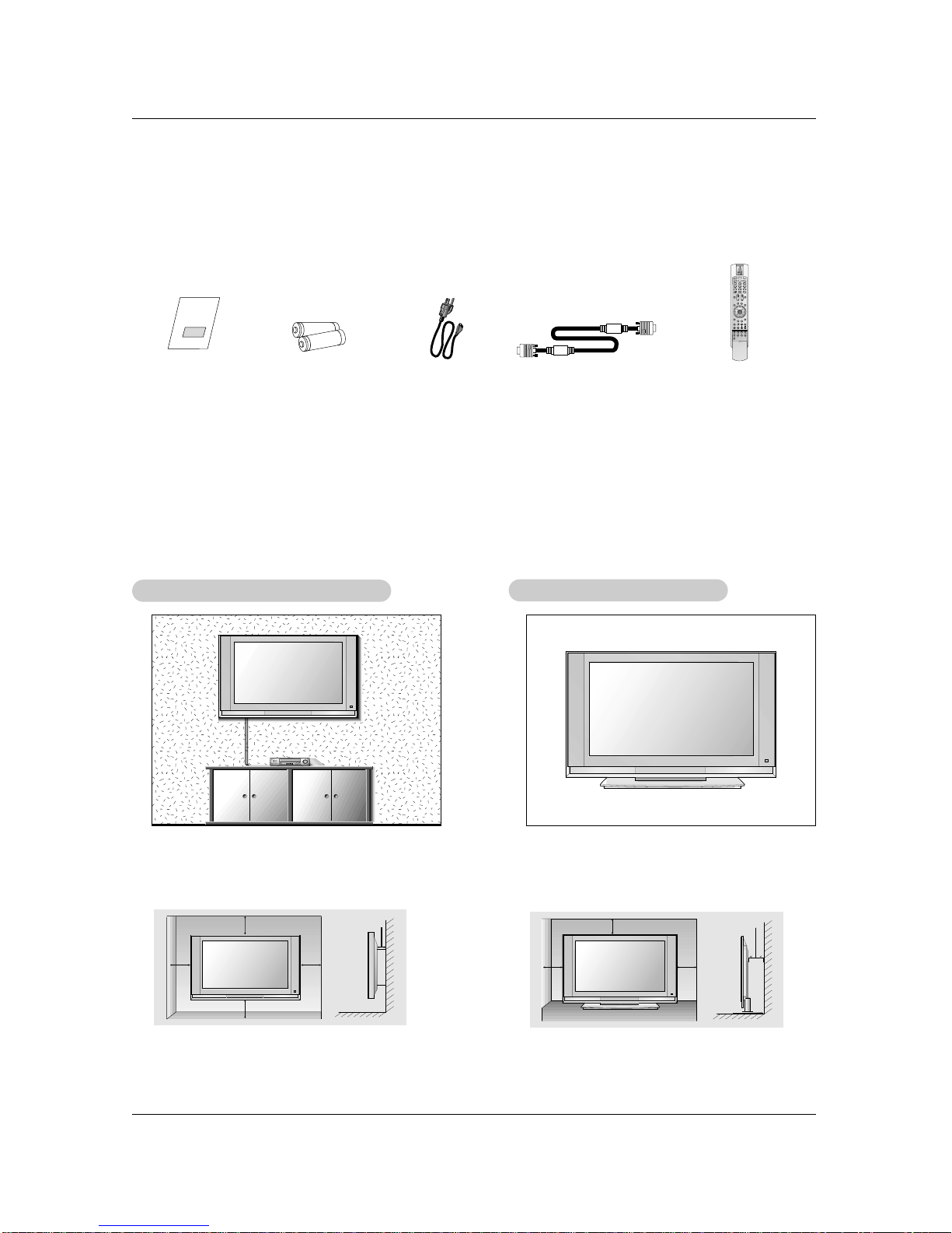
Setup and Operation Checklist
(See pages 11~15 for available connection and operational setup options.)
1. Unpack TV and all accessories.
2. Connect all external video and audio equipment.
see pages 11 ~ 15.
3 Install batteries in remote control.
See page 8.
4. Turn TV on.
See page 17.
5. Turn video source equipment on.
6. Select viewing source for TV.
See page 20.
7. Fine-tune source image and sound to your personal prefer-
ence or as required by source.
See pages 21 ~ 24.
8. Additional features set up
See Contents above.

6
Introduction
Introduction
Introduction
CH
VOL
ENTER
MENU
VIDEO
ON/OFF
TV
/I
TV/VIDEO Button
VOLUME (FF,GG) Buttons
Power Standby Indicator
Illuminates brightly when the TV
is in standby mode. Dims when
the TV is switched on.
- This is a simplified representation of front panel.
Here shown may be somewhat different from your TV.
- This manual explains the features available on the DU-42LZ30 TV.
Remote Control Sensor
CHANNEL (EE, DD) Buttons
MENU Button
ENTER Button
ON/OFF Button
Front Panel Controls

7
Introduction
Connection Options
Connection Options
Antenna1 Antenna 2
S-VIDEO
REMOTE
CONTROL UPGRADE
PORT RGB INPUT
(PC/DTV INPUT)
DVI INPUT
(PC/DTV INPUT)
AC INPUT AUDIO INPUT
AUDIO VIDEO
VIDEO INPUT
DIGITAL AUDIO
(OPTICAL)
COMPONENT 2
MONITOR
OUTPUT
A/V
INPUT1
(MONO)
DVD
/DTV
INPUT
COMPONENT 1
DVI
INPUT
PC/DVI
AUDIO INPUT
RL R L
COMPONENT1
INPUT
OUTPUT
S-VIDEO
IN2
VIDEOL/MONOAUDIOR
Back Connection Panel
Antenna1 Input
RGB Input (PC/DTV Input)
PC/DTV Audio Input
Digital Audio Inputs (DVI, Component1)/
Digital Audio Output
Audio/Video Input 1
DVD/DTV Input (Component 1,2)
Monitor Output
Remote Control Port S-Video Input
DVI Input (PC/DTV Input)
Antenna2 Input
Power Cord Socket
Upgrade Port
- This manual explains the features available on the DU-42LZ30 TVs.
S-VIDEO Input
VIDEO Input
AUDIO Input
DVI INPUT
(PC/DTV INPUT)
DVI Input (PC/DTV Input)
* DU-30LZ30

8
Introduction
- When using the remote control, aim it at the remote control sensor on the TV.
LIGHT
TV/VIDEO
MODE
COMP/RGB/DVI
MUTE SURF
VOL CH
INFO
SAP RATIO
CC
MENU
SOUND VIDEO
EXIT
PLAY PAUSE STOP RECORD
PIP PIPCH- PIPCH+ PIPINPUT
FREEZE
ADJUST
ENTER
ZOOM SIGNAL SWAP
REW FF SKIP
POWER
TIMER
FLASHBK
LIGHT
Illuminates the remote control buttons.
TV/VIDEO
Selects: DTV, Analog, Video1-2,
Component 1-2, RGB-DTV (or RGB-PC),
DVI-DTV (or DVI-PC) input sources.
COMP/RGB/DVI
Selects: Component 1-2, RGB-DTV (or RGB-
PC), DVI-DTV (or DVI-PC) input sources.
NUMBER buttons
DASH
Used to enter a program number for multiple
program channels such as 2-1,2-2,etc.
MUTE
Switches the sound on or off.
VCR/DVD BUTTONS
Control some video cassette recorders or
DVD player ("RECORD" button is not avail-
able for DVD player).
RATIO
Changes the aspect ratio.
MODE
Selects the remote operating mode: TV,
VCR, DVD, CABLE, HDSTB or AUDIO.
Select other operating modes, for the
remote to operate external devices.
POWER
Turns your TV or any other programmed
equipment on or off, depending on mode.
TIMER
Lets you select the amount of time before
your TV turns itself off automatically.
SURF
Use to scroll the Surf channel list.
CC
Select a closed caption:
Off, EZ Mute, and On.
FLASHBK
Tunes to the last channel viewed.
THUMBSTICK (Up/Down/Left/Right/ENTER)
Allows you to navigate the on-screen
menus and adjust the system settings to
your preference.
CHANNEL UP/DOWN
Selects available channels found
with EZ scan.
EXIT
Clears all on-screen displays and returns to
TV viewing from any menu.
VIDEO
Adjusts the factory preset picture according
to the room.
VOLUME UP/DOWN
Increases/decreases the sound level.
SAP
Selects MTS sound: Mono, Stereo, and SAP.
Change the audio language in DTV mode.
MENU
Brings up the main menu to the screen.
INFO
When you watch the TV, displays information
on top of the screen. Not available in
Component 1-2, RGB and DVI mode.
SOUND
Selects the sound appropriate
for the program's character. PIP
Switches between PIP, POP (Picture-out-of-
Picture) and Twin picture modes.
PIPCH-/PIPCH+
Changes to next higher/lower PIP channel.
PIP INPUT
Selects the input source for the sub picture.
SWAP
Exchanges the PIP/main images.
FREEZE
Freezes the currently-viewed picture. Main
picture is frozen in PIP/Twin picturre mode.
ADJUST
Adjusts screen position, clock, and
phase in PC mode.
ZOOM
Enlarges the main picture size.
SIGNAL
Displays the digital signal strength.
Installing Batteries
•Open the battery compartment cover on the back side and install the batteries
matching correct polarity (+ with +, - with -).
•Install two 1.5V AA batteries. Don’t mix old or used batteries with new ones.
Replace cover.
Remote Control Key Functions

9
Installation
Installation
Installation
Owner’s Manual
1.5V
1.5V
Batteries Power Cord
LIGHT
TV/VIDEO
MODE
COMP/RGB/DVI
MUTE SURF
VOL CH
INFO
SAP RATIO
CC
MENU
SOUND VIDEO
EXIT
PLAY PAUSE STOP RECORD
PIP PIPCH- PIPCH+ PIPINPUT
FREEZE
ADJUST
ENTER
ZOOM SIGNAL SWAP
REW FF SKIP
POWER
TIMER
FLASHBK
Remote Control
Ensure that the following accessories are included with your plasma display. If an accessory is missing, please contact the dealer
where you purchased the product.
4 inches
4 inches
4 inches4 inches
2 inches
W
Wall Mount: Horizontal installation
all Mount: Horizontal installation
For proper ventilation, allow a clearance of 4”on each
side and 2”from the wall. Detailed installation instruc-
tions are available from your dealer, see the optional
Wall Mounting Bracket Installation and Setup Guide.
4 inches
4 inches4 inches
2 inches
Desktop Pedestal Installation
For proper ventilation, allow a clearance of 4”on each
side and the top, 2.36”on the bottom, and 2”from the
wall. Detailed installation instructions are included in
the optional Desktop Stand Installation and Setup
Guide available from your dealer.
D-sub 15 pin Cable
Installation Instruction

10
Installation
W
Wire Holders
ire Holders
- Thread, then pull the wires through the hole on the TV stand.
Rear
Rear A/V Cover
A/V Cover
* The connection panel is hidden behind the A/V cover.
a. Remove the cover.
b. Install wires as necessary.
c. Reinstall the cover. Position the A/V cover with the TV back panel.
d. Align the holes on the TV back panel with the two tuberance on the rear A/V cover and insert.
e. Close cover.
Installation Instruction
- This manual explains the features available on the DU-42LZ30 TVs.

11
Installation
- Antenna or Cable Service without a Cable Box Connections
- For optimum picture quality, adjust antenna direction if needed.
Antenna Connection
Antenna Connection
Analog and Digital TV signals provided on one antenna
NOTE: If you are not sure of the type of signal(s) you are receiving, let EZ Scan complete all the channel signal-type searches.
The TV will let you know when the analog, cable, and digital channel scans are complete.
Analog and Digital TV signals provided on two separate antennas
•In a poor signal area to improve picture quality, purchase
and install a signal amplifier.
•If the antenna needs to be split for two TV’s, install a “2-
Way Signal Splitter”in the connections.
•If the antenna is not installed properly, contact your deal-
er for assistance.
Antenna1 Antenna 2
DVI INPUT
(PC/DTV INPUT)
Signal
Amplifier
Antenna1 Antenna 2
S-VIDEO
DVI INPUT
(PC/DTV INPUT)
Multi-family Dwellings/Apartments
(Connect to wall antenna socket)
Single-family Dwellings /Houses
(Connect to wall jack for outdoor antenna)
Outdoor
Antenna
Wall Antenna
Socket
VHF Antenna
UHF Antenna
RF Coaxial Wire (75 ohm)
Bronze Wire
Turn clockwise to tighten.
Bronze Wire
Be careful not to bend the bronze wire when
connecting the antenna.
Antenna1 Antenna 2
S-VIDEO
DVI INPUT
(PC/DTV INPUT)
Wall Antenna
Socket RF Coaxial Wire (75 ohm)
Analog Antenna
Digital Antenna
Bronze Wire
Bronze Wire
Turn clockwise to tighten.
Wall Antenna
Socket RF Coaxial Wire (75 ohm)
External Equipment Connections

12
Installation
NOTE: All cables shown are not included with the TV
- To avoid picture noise (interference), leave an adequate distance between the VCR and TV
- Typically a frozen still picture from a VCR. If the 4:3 picture format is used; the fixed images on the sides of the screen may
remain visible on the screen.
Connection Option 1
Set VCR output switch to 3 or 4 and then tune
TV to the same channel number.
Connection Option 2
1. Connect the audio and video cables from the
VCR's output jacks to the TV input jacks, as
shown in the figure.
When connecting the TV to VCR, match the
jack colors (Video = yellow, Audio Left = white,
and Audio Right = red).
If you connect an S-VIDEO output from VCR to
the S-VIDEO input, the picture quality is
improved; compared to connecting a regular
VCR to the Video input.
2. Insert a video tape into the VCR and press
PLAY on the VCR. (Refer to the VCR owner’s
manual.)
3. Select the input source with using the
TV/VIDEO button on the remote control. (If
connected to A/V INPUT 1, select Video 1
input source)
Do not connect to both Video and
S-Video at the same time.
VCR Setup
VCR Setup
Antenna1 Antenna 2
S-VIDEO
RGB INPUT
(PC/DTV INPUT)
DVI INPUT
(PC/DTV INPUT)
AUDIO INPUT
AUDIO VIDEO
VIDEO INPUT
COMPONENT 2
MONITOR
OUTPUT
A/V
INPUT1
(MONO)
DVD
/DTV
INPUT
COMPONENT 1
RL R L
S-VIDEO OUT
IN
(R) AUDIO (L) VIDEO
34
OUTPUT
SWITCH
ANT OUT
ANT IN
- After subscribing to a cable TV service from a local provider and installing a converter, you can watch cable TV programming.
The TV cannot display TV programming unless a TV tuner device or cable TV converter box is connected to the TV.
- For further information regarding cable TV service, contact your local cable TV service provider(s).
Connection Option 1
1. Select 3 or 4 with channel switch on cable box.
2. Tune the TV channel to the same selected output channel on
cable box.
3. Select channels at the cable box or with the cable box remote
control.
Connection Option 2
1. Connect the audio and video cables from the Cable Box's output
jacks to the TV input jacks, as shown in the figure.
When connecting the TV to a Cable Box, match the jack colors
(Video = yellow, Audio Left = white, and Audio Right = red).
2. Select the input source with using the TV/VIDEO button on the
remote control. (If connected to A/V INPUT 1, select Video 1 input
source)
3. Select your desired channel with the remote control for cable box.
Cable
Cable TV Setup
TV Setup
Antenna1 Antenna 2
S-VIDEO
DVI INPUT
(PC/DTV INPUT)
AUDIO INPUT
AUDIO VIDEO
VIDEO INPUT
COMPONENT 2
MONITOR
OUTPUT
A/V
INPUT1
(MONO)
DVD
/DTV
INPUT
COMPONENT 1
RL R L
TV
VCR RF Cable
(R) AUDIO (L) VIDEO
34
OUTPUT
SWITCH
VCR
Cable Box
1
2
1
2

13
Installation
•Component Input ports
To get better picture quality, connect a DVD player
to the component input ports as shown below.
How to connect
Connect the audio and video cables from the external equip-
ment's output jacks to the TV input jacks, as shown in the
figure.
When connecting the TV to external equipment, match the
jack colors (Video = yellow, Audio Left = white, and Audio
Right = red).
How to use
1. Select the input source with using the TV/VIDEO button on
the remote control. (If connected to A/V INPUT 1, select
Video 1 input source).
2. Operate the corresponding external equipment. Refer to
external equipment operating guide.
Component ports
on the TV YPBPR
Video output ports
on DVD player
Y
Y
Y
Y
Pb
B-Y
Cb
PB
Pr
R-Y
Cr
PR
How to connect
1. Connect the DVD video outputs (Y, PB, PR) to the COM-
PONENT (Y, PB, PR) INPUT jacks on the TV and connect
the DVD audio outputs to the AUDIO INPUT jacks on the
TV, as shown in the figure.
2. If your DVD only has an S-Video output jack, connect this
to the S-VIDEO input on the TV and connect the DVD
audio outputs to the AUDIO INPUT jacks on the TV, as
shown in the figure.
NOTE: If your DVD player does not have component video
output, use S-Video.
How to use
1. Turn on the DVD player, insert a DVD.
2. Use the TV/VIDEO or COMP/RGB/DVI button on the
remote control to select Component 1 or Component 2.
(If connected to S-VIDEO, select the Video 1 or Video 2
external input source.)
3. Refer to the DVD player's manual for operating instruc-
tions.
External
External A/V Source Setup
A/V Source Setup
DVD Setup
DVD Setup
S-VIDEO
AUDIO INPUT
AUDIO VIDEO
VIDEO INPUT
COMPONENT 2
MONITOR
OUTPUT
A/V
INPUT1
(MONO)
DVD
/DTV
INPUT
COMPONENT 1
RL R L
RL
AUDIO VIDEO
S-VIDEO
RGB INPUT
(PC/DTV INPUT) AUDIO INPUT
AUDIO VIDEO
VIDEO INPUT
DIGITALAUDIO
(OPTICAL)
COMPONENT 2
MONITOR
OUTPUT
A/V
INPUT1
(MONO)
DVD
/DTV
INPUT
COMPONENT 1
DVI
INPUT
PC/DVI
AUDIO INPUT
RL R L
COMPONENT1
INPUT
OUTPUT
BR
(R) AUDIO (L)
DIGITAL AUDIO
OPTICAL (R) AUDIO (L)
S-VIDEO
DVD
or
Camcorder
Video Game Set
The TV has a special signal output capability which allows you to hook up a sec-
ond TV or monitor.
Connect the second TV or monitor to the TV’s MONITOR OUTPUT. See the
Operating Manual of the second TV or monitor for further details regarding that
device’s input settings.
NOTE
•Component, RGB-PC/RGB-DTV, DVI-PC/DVI-DTV, DTV input sources cannot
be used for Monitor out.
NOTES
•Digital Audio will not work for Component 2 input source.
•Digital Audio operation has priority if Digital Audio and AUDIO L/R
are connected at the same time.
S-VIDEO IN
(R) AUDIO (L) VIDEO
S-VIDEO
AUDIO INPUT
AUDIO VIDEO
VIDEO INPUT
COMPONENT 2
MONITOR
OUTPUT
A/V
INPUT1
(MONO)
DVD
/DTV
INPUT
COMPONENT 1
RL R L
Monitor Out Setup
Monitor Out Setup
or

14
Installation
Send the TV’s audio to external audio equipment (stereo system) via
the Digital Audio Output Optical port.
How to connect
1. Connect one end of an optical cable to the TV Digital Audio Optical
Output port.
2. Connect the other end of the optical cable to the digital audio optical
input on the audio equipment.
3. Set the “TV Speaker option - Off”in the AUDIO menu. Refer to
page 23.
See the external audio equipment instruction manual for operation.
Caution: Do not look into the optical output port.
Looking at the laser beam may damage
your vision.
Digital
Digital Audio Output
Audio Output
- This TV can receive Digital Over-the-air/Cable signals without an external digital set-top box. However, if you do receive Digital
signals from a digital set-top box or other digital external device, refer to the figure as shown below.
- This TV supports HDCP (High-bandwidth Digital Contents Protection) protocol for DTV (480p,720p,1080i) mode.
How to connect
Use the TV’s COMPONENT (Y, PB, PR) INPUT, RGB or DVI jack for
video connections, depending on your set-top box connector. Then,
make the corresponding audio connections.
How to use
1. Turn on the digital set-top box. (Refer to the owner’s manual for the
digital set-top box.)
2. Use TV/VIDEO or COMP/RGB/DVI on the remote control to select
Component 1, Component 2, RGB-DTV, or DVI-DTV source.
HDSTB Setup
HDSTB Setup
UPGRADE
PORT RGB INPUT
(PC/DTV INPUT)
DIGITALAUDIO
(OPTICAL)
DVI
INPUT
PC/DVI
AUDIO INPUT
COMPONENT1
INPUT
OUTPUT
S-VIDEO
RGB INPUT
(PC/DTV INPUT) AUDIO INPUT
AUDIO VIDEO
VIDEO INPUT
DIGITALAUDIO
(OPTICAL)
COMPONENT 2
MONITOR
OUTPUT
A/V
INPUT1
(MONO)
DVD
/DTV
INPUT
COMPONENT 1
DVI
INPUT
PC/DVI
AUDIO INPUT
RL R L
COMPONENT1
INPUT
OUTPUT
BR
(R) AUDIO (L)
(R) AUDIO (L)
RGB-DTV OUTPUT
DIGITAL AUDIO
OPTICAL
Antenna1 Antenna 2
S-VIDEO
RGB INPUT
(PC/DTV INPUT)
DVI INPUT
(PC/DTV INPUT)
AUDIO INPUT
AUDIO VIDEO
VIDEO INPUT
DIGITALAUDIO
(OPTICAL)
COMPONENT 2
MONITOR
OUTPUT
A/V
INPUT1
(MONO)
DVD
/DTV
INPUT
COMPONENT 1
DVI
INPUT
PC/DVI
AUDIO INPUT
RL R L
COMPONENT1
INPUT
OUTPUT
(R) AUDIO (L)
DVI-DTV OUTPUT
DIGITAL AUDIO
OPTICAL
Digital Set-top Box
or
or
or
or
REMOTE
CONTROL UPGRADE
PORT
DIGITALAUDIO
(OPTICAL)
DVI
INPUT
PC/DVI
AUDIO INPUT
COMPONENT1
INPUT
OUTPUT
Signal
480i
480p
720p
1080i
Component 1/2
Yes
Yes
Yes
Yes
RGB-DTV,DVI-DTV
No
Yes
Yes
Yes

15
Installation
How to connect
1. To get the best picture quality, adjust the PC
graphics card to 1024x768, 60Hz.
2. Use the TV’s RGB INPUT or DVI (Digital Visual
Interface) INPUT port for video connections,
depending on your PC connector.
•If the graphic card on the PC does not output
analog and digital RGB simultaneously, connect
only one of either RGB INPUT or DVI INPUT to
display the PC on the TV.
•If the graphic card on the PC does output analog
and digital RGB simultaneously, set the TV to
either RGB or DVI; (the other mode is set to Plug
and Play automatically by the TV.)
3. Then, make the corresponding audio connections.
If using a sound card, adjust the PC sound as
required.
How to use
1. Turn on the PC and the TV.
2. Turn on the display by pressing the POWER button on the TV's remote control.
3. Select RGB-PC or DVI-PC input source in main input option of SETUP menu. (Refer to P.20)
4. Check the image on your TV. There may be noise associated with the resolution, vertical pattern, contrast or bright-
ness in PC mode. If noise is present, change the PC mode to another resolution, change the refresh rate to another
rate or adjust the brightness and contrast on the menu until the picture is clear. If the refresh rate of the PC graphic
card can not be changed, change the PC graphic card or consult the manufacturer of the PC graphic card.
NOTES: •Depending on the graphics card, DOS mode may not work if you use a DVI-I cable.
•Avoid keeping a fixed image on the TV's screen for a long period of time. The fixed image may become per-
manently imprinted on the screen. Use the Orbiter screen saver when possible.
•The synchronization input form for Horizontal and Vertical frequencies is separate.
PC Setup
PC Setup
Antenna1 Antenna 2
S-VIDEO
RGB INPUT
(PC/DTV INPUT)
DVI INPUT
(PC/DTV INPUT)
AUDIO INPUT
AUDIO VIDEO
VIDEO INPUT
COMPONENT 2
MONITOR
OUTPUT
A/V
INPUT1
(MONO)
DVD
/DTV
INPUT
COMPONENT 1
RL R L
PC/DVI
AUDIO INPUT
- This TV provides Plug and Play capability, meaning that the PC adjusts automatically to the TV's settings. The TV sends config-
uration information (EDID) to the PC using the Video Electronics Standard Association (VESA) Display Data Channel (DDC)
protocol.
- The TV perceives 640x480, 60Hz as DTV 480p based on the PC graphic card. card, change the screen scanning rate for the
graphic card accordingly.
Resolution
640x350
720x400
640x480
800x600
Horizontal
Frequency(KHz)
31.468
31.469
37.927
31.469
37.861
37.500
43.269
70.09
70.08
85.03
59.94
72.80
75.00
85.00
35.156
37.879
48.077
46.875
53.674
48.363
56.476
60.023
56.25
60.31
72.18
75.00
85.06
60.00
70.06
75.02
Vertical
Frequency(Hz) Resolution Horizontal
Frequency(KHz) Vertical
Frequency(Hz)
1024x768
Monitor Display Specifications (RGB-PC / DVI-PC Mode)

16
Operation
Operation
Operation
- Be sure to select the RGB-PC/RGB-DTV source before operation.
(For RGB-DTV input source, Position and Reset are available.)
- In DVI-PC and DVI-DTV input source, settings are not adjustable.
- You can manually adjust picture position and minimize image shaking for the PC input source.
1. Press the ADJUST button and then use DD / EEbutton to select POSITION,
CLOCK, or PHASE.
2. Press OK button and then use DD / EE/ FF / GG buttons to make appropriate adjust-
ments.
•The PHASE adjustment range is -16 ~ +16.
•The CLOCK adjustment range is -30 ~ +30.
3. Press OK button.
Adjustment for screen Position, Clock, and Phase
Screen Setup for PC mode
1. Press the ADJUST button and then use DD / EEbutton to select the RESET option.
2. Press OK button and then use FF / GG button to select Yes.
3. Press OK button
Initializing (Reset to original factory values)
- To initialize the adjusted values
Close
POSITION GG
CLOCK
PHASE
RESET
Adjust
DD
FFGG
EE
Close
POSITION
CLOCK
PHASE
RESET GG
Adjust
Initialize Settings

17
Operation
On-screen Menus Language Selection
T
Turning the TV On
urning the TV On
Turning on the TV just after installation
Turning on the TV (power cord is still connected)
1. Connect power cord correctly.
2. Press the ON/OFF button on the TV. At this moment, the TV is switched to standby mode.
Press the TV/VIDEO, CH (DD/ EE)button on the TV or press the POWER, TV/VIDEO,
COMP/RGB/DVI, CH (+, -), Number (0 ~ 9) button on the remote control and then the TV will
switch on.
•Press the ON/OFF button on the TV to turn the TV on.
1. If the TV was turned off with the ON/OFF button on the TV
2. If the TV was turned off with the remote control and then the ON/OFF button on the TV
•Press the ON/OFF button on the TV and then press the POWER, TV/VIDEO, COMP/RGB/DVI,
CH (+, -), Number (0 ~ 9) button on the remote control to turn the TV on.
-The menus can be shown on the screen in the selected language. First select your language.
1. Press the MENU button and then use DD/ EEbutton to select the OPTION menu.
2. Press the GGbutton and then use DD/ EEbutton to select Language.
3. Press the GGbutton and then use DD/ EEbutton to select your desired language.
From this point on, the on-screen menus will be shown in the selected language.
4. Press EXIT button to return to TV viewing or press MENU button to return to the
previous menu.
NOTE
•If you intend to be away on vacation, disconnect the power plug from the wall power outlet.
SETUP
VIDEO
AUDIO
TIME
OPTION
LOCK Prev.
Aspect Ratio
Caption
Caption Mode
Caption Option
Language GG
Cinema
Demo
English
Español
Français
MENU

18
Operation
SETUP
VIDEO
AUDIO
TIME
OPTION
LOCK Prev.
Select antenna input,
press
MENU
Air
ANT 1 ANT 2
- Automatically finds all channels available through antenna or cable inputs, and stores them in memory on the channel list.
- Run EZ Scan again after any Antenna/Cable connection changes.
1. Press the MENU button and then use DD / EEbutton to select the SETUP menu.
2. Press the GGbutton and then use DD / EEbutton to select EZ Scan.
3. Press the GGbutton and then use DD / EEbutton to select antenna input (Based on your connections to antenna 1-2).
•Analog/DTV Air:
Watching the Over-the-air, cable, and digital over-the-air signals via antenna 1 input port
•Analog/DTV Cable:
Watching the Over-the-air, cable, and digital cable signals via antenna 1 input port
•Analog+DTV Air (ANT2):
Watching the Over-the-air, and cable signal via antenna 1 input port and the digital over-the-air signal via antenna 2 input port
•Analog/DTV Cable (ANT2):
Watching the Over-the-air, and cable signa lvia antenna 1 input port and the digital cable signal via antenna 2 input port
* Cable Service Band Note: Select STD=Standard, HRC=HRC Band, or IRC=IRC Band.
(For further band information, contact your cable service provider.)
4. Press the OK button to begin the channel search.
Allow EZ Scan to complete the channel search cycle for TV, CATV, and DTV/CADTV.
EZ Scan (Channel Search)
SETUP
VIDEO
AUDIO
TIME
OPTION
LOCK Prev.
EZ Scan
Ch.Edit GG
DTV Signal
Ch. Label
Main Input
Sub Input
Front Display
SET ID
Selection (
GG
or ) leads you
to the channel edit screen.
MENU
- Create two different types of channel lists in memory: “Custom list”and “Surf"
(Favorite) channel list”from the default channel list created from the EZ Scan
channel search.
- A custom list can be created by toggling each channel on or off with OK button.
Once a channel is highlighted, you will be able to see whether the channel is
currently added or deleted by referring to the small window at the top-left corner
of the screen. You can create your own Surfchannel list with up to 10 channels.
It appears at the bottom-left corner of the screen. Use the SURF button on the
remote control when a channel is highlighted, to add or delete the channel from
the Surf channel list.
- You can create your SURF channel list from the channel list memorized from
EZ Scan.
- CATV is available for 1-125 channel.
1. Press the MENU button and then use DD / EEbutton to select the SETUP menu.
2. Press the GGbutton and then use DD / EEbutton to select Ch. E it.
3. Press the GGbutton. You will now see a screen filled with channel numbers and
a preview picture.
4. Use DD / EE/ FF / GGbutton to select a channel and then use the OK button to add
or delete it. Press SURF to add the channel to the Surf List.
5. Press EXIT button to return to TV viewing or press MENU button to return to the
previous menu.
Channel Edit
Channel Edit
Setup Menu Options
Setup Menu Options
Analog/DTV Air
Analog/DTV Cable
Analog+DTV Air(ANT2)
Analog+DTV Cable(ANT2)
Prev.
Select antenna input,
press
MENU
Cable
ANT 1 ANT 2
Analog/DTV Air
Analog/DTV Cable
Analog+DTV Air(ANT2)
Analog+DTV Cable(ANT2)
Prev.
Select antenna input,
press
MENU
Cable Air
ANT 1 ANT 2
Analog/DTV Air
Analog/DTV Cable
Analog+DTV Air(ANT2)
Analog+DTV Cable(ANT2)
Prev.
Select antenna input,
press
MENU
Air Cable
ANT 1 ANT 2
Analog/DTV Air
Analog/DTV Cable
Analog+DTV Air(ANT2)
Analog+DTV Cable(ANT2)
EZ Scan
Ch.Edit
DTV Signal
Ch. Label
Main Input
Sub Input
Front Display
SET ID
Select DTV cable band,
press
1. STD
2. HRC
3. IRC

19
Operation
- Reveals how strong your DTV signal is and whether you need to adjust your antenna or digital cable input.
The higher the signal strength, the less likely you are to experience picture degradation.
- Digital DTV Signals: May not be available in all areas, nor are broadcast on all programs.
1. Press the SIGNAL button.
2. View the on-screen signal strength monitor to see the quality of the signal being received.
•You can also check the DTV Signal strength with the SETUP menu.
DTV Signal Strength
DTV Signal Strength
SETUP
VIDEO
AUDIO
TIME
OPTION
LOCK Prev.
EZ Scan
Ch.Edit
DTV Signal
Ch. Label GG
Main Input
Sub Input
Front Display
SET ID
MENU
Selection (
GG
or ) leads you
to the channel logo screen.
- Choose preset labels for your channels.
- If a channel label is provided on the signal from the broadcasting station, the TV displays a short name for a DTV chan-
nel - even if you didn't preset a label for the channel.
1. Press the MENU button and then use DD / EEbutton to select the SETUP menu.
2. Press the GGbutton and then use DD / EEbutton to select Ch.Label.
3. Press the GGbutton. You will now see a screen filled with Labels and a preview screen.
4. Use the CH +/- button to select a channel to Label.
5. Use DD / EE/ FF / GG button to select the appropriate label for the channel, then press OK button to set the Label to the
selected channel.
6. Press EXIT button to return to TV viewing or press MENU button to return to the previous menu.
Channel Label Setup
Channel Label Setup

20
Operation
- Illuminates brightly when the set is turned on. The LED displays current
TV status.
1. Press the MENU button and then use DD / EEbutton to select the SETUP menu.
2. Press the GGbutton and then use DD / EEbutton to select Front Display.
3. Press the GGbutton and then use DD / EEbutton to select Off, Dark, Normal, and
Bright.
4. Press EXIT button to return to TV viewing or press MENU button to return to the
previous menu.
Front LED (Light Emitting Diode) Display
SETUP
VIDEO
AUDIO
TIME
OPTION
LOCK Prev.
EZ Scan
Ch.Edit
DTV Signal
Ch. Label
Main Input
Sub Input
Front Display GG
SET ID
Off
On
MENU
Setup Menu Options continued
- Changes the picture source so you can watch your off-air TV, cable TV, VCR, DVD, or any other devices that are connected to
your TV.
1. Press the MENU button and then use DD / EEbutton to select the SETUP menu.
2. Press the GGbutton and then use DD / EEbutton to select Main Input.
3. Press the GGbutton and then use DD / EEbutton to select the source: DTV, Analog,
Video1, Video2, Component1, Component2, RGB-DTV (or RGB-PC), DVI-DTV
(or DVI-PC).
4. Press EXIT button to return to TV viewing or press MENU button to return to the
previous menu.
Main Picture Source Selection
SETUP
VIDEO
AUDIO
TIME
OPTION
LOCK Prev.
EZ Scan
Ch.Edit
DTV Signal
Ch. Label
Main Input GG
Sub Input
Front Display
SET ID
DTV
Analog
Video1
Video2
Component1
Component2
RGB-DTV
DVI-DTV
MENU
Other manuals for DU-30LZ30
3
This manual suits for next models
2
Table of contents
Other LG LCD TV manuals