LG M2080DF User manual

G
Order Number : GETEC-C1-10-124 FCC Part 15 subpart B
Test Report Number : GETEC-E3-10-065 Page 1 / 1
EUT Type: LED LCD TV/Monitor
FCC ID.: BEJM2280DFM
APPENDIX G
: USER’S MANUAL

www.lg.com
OWNER’S MANUAL
LED LCD MONITOR TV
LED LCD MONITOR TV MODELS
M2080DF
M2280DF
M2380DF
Please read this manual carefully before operating
your set and retain it for future reference.
ENGLISH

CONTENTS
CONTENTS
PREPARATION
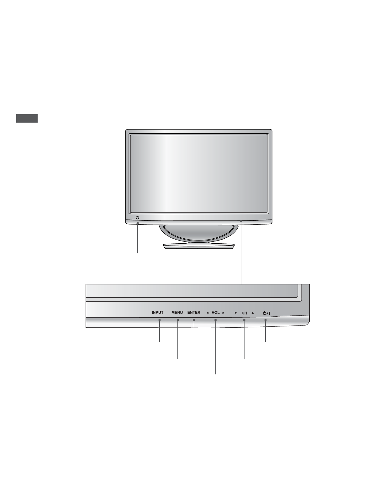
FRONT PANEL CONTROLS .................................... 4
BACK PANEL INFORMATION.................................5
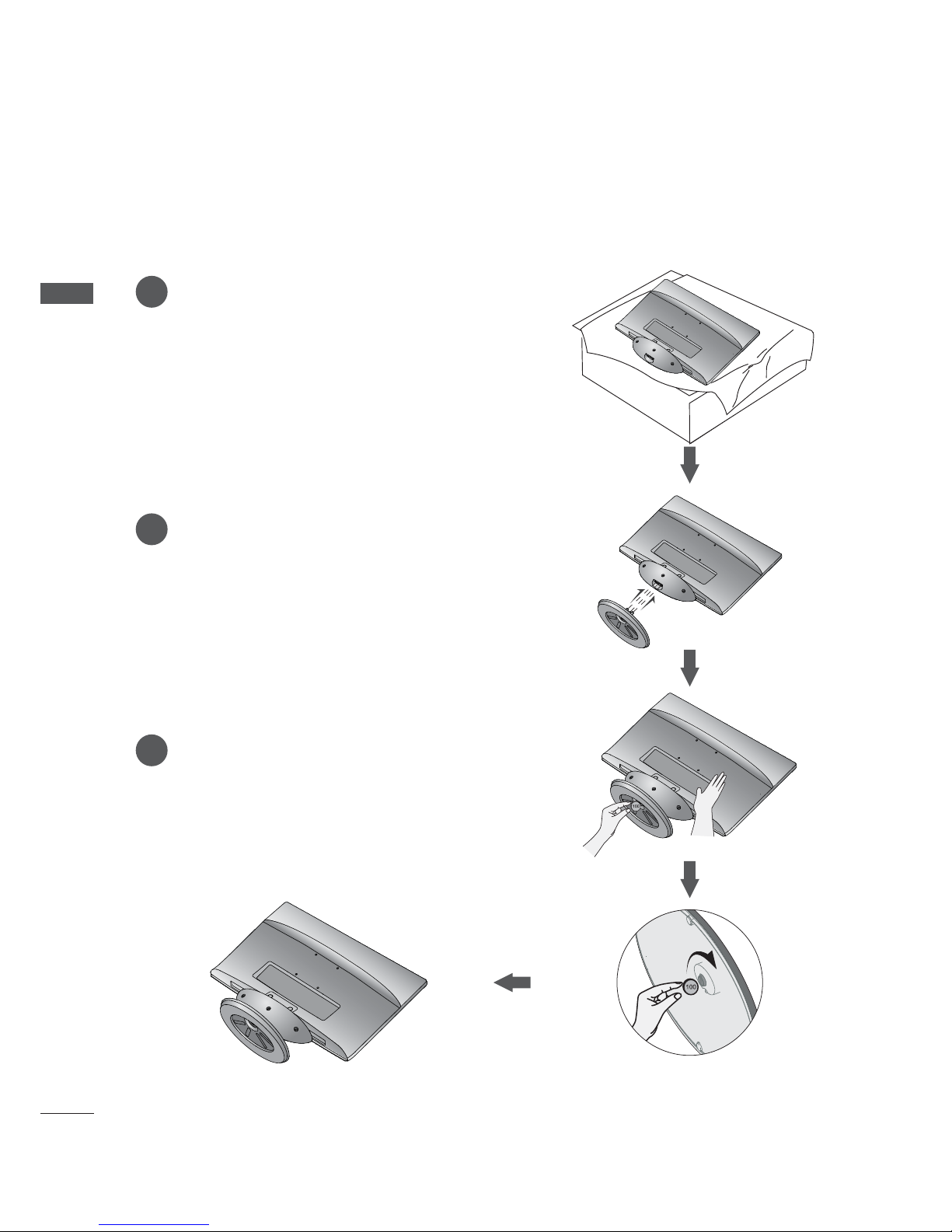
STAND INSTALLATION............................................. 6
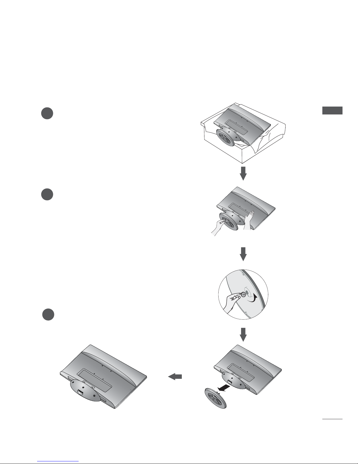
DETACHING STAND................................................... 7
WALL MOUNT: HORIZONTAL INSTALLATION ....8
DESKTOP PEDESTAL INSTALLATION ................. 9
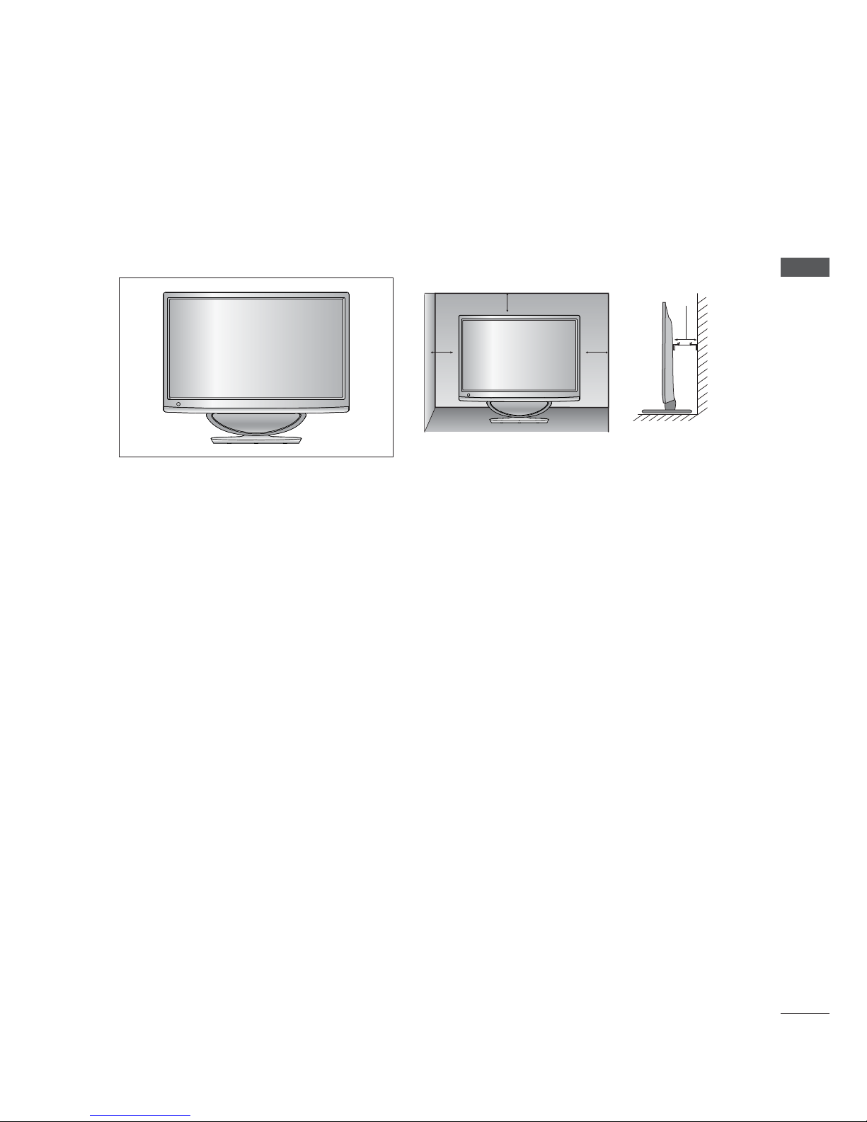
POSITIONING YOUR DISPLAY ............................. 10
LOCATION................................................................... 10
KENSINGTON SECURITY SYSTEM .......................11
EXTERNAL EQUIPMENT SETUP
ANTENNA CONNECTION .......................................12
HD RECEIVER SETUP
Connecting with a component cable..............13
Connecting a set-top box with a HDMI cable ......14
Connecting with an HDMI to DVI cable ........ 15
DVD SETUP
Connecting with a component cable..............16
When connecting HDMI cable..........................17
VCR SETUP
Connecting with a RF cable.............................. 18
Connecting with a RCA cable...........................19
DIGITAL AUDIO OUT SETUP............................... 20
USB SETUP..................................................................21
HEADPHONE SETUP.............................................. 22
OTHER A/V SOURCE SETUP.............................. 23
PC SETUP
When connecting with a D-sub 15 pin cable.......24
Connecting with an HDMI to DVI cable ....... 25
Connecting with an HDMI to HDMI cable........ 26
BACK COVER FOR WIRE ARRANGEMENT.....27
SUPPORTED DISPALY RESOLUTION............... 28
WATCHING TV / PROGRAMME
CONTROL
REMOTE CONTROL KEY FUNCTIONS............. 30
TURNING ON THE TV ............................................ 32
PROGRAMME SELECTION................................... 32
VOLUME ADJUSTMENT........................................ 32
INITIAL SETTING...................................................... 33
QUICK MENU............................................................ 34
ON SCREEN MENUS SELECTION AND
ADJUSTMENT........................................................... 35
AUTO SCAN (AUTO TUNING)............................. 36
ADD/DELETE CHANNEL (MANUAL TUNING) .......37
CHANNEL EDITING................................................. 38
CHANNEL LIST......................................................... 39
FAVORITE CHANNEL SETUP............................... 40
FAVORITE CHANNEL LIST.................................... 40
BRIEF INFORMATION...............................................41
INPUT LIST................................................................. 42
PICTURE CONTROL
PICTURE SIZE (ASPECT RATIO) CONTROL .. 43
PICTURE WIZARD ................................................... 45
ᭆENERGY SAVING............................................... 46
PRESET PICTURE SETTINGS ...............................47
MANUAL PICTURE ADJUSTMENT ................... 48
PICTURE IMPROVEMENT TECHNOLOGY ....... 49
EXPERT PICTURE CONTROL.............................. 50
PICTURE RESET....................................................... 53
SCREEN SETUP FOR PC MODE
Selecting Resolution .......................................... 54
Auto Configure (RGB [PC] mode only) ....... 55
Adjustment for screen Position, Size, Phase ....... 56
Screen Reset .........................................................57
SOUND CONTROL
AUTO VOLUME LEVELER (AUTO VOLUME) .. 58
CLEAR VOICE II........................................................ 59
BALANCE ................................................................... 60
PRESET SOUND SETTINGS
(SOUND MODE)....................................................61
PRESET SOUND SETTINGS
-USER MODE........................................................ 62
Surround X.................................................................. 62
AUDIO RESET ........................................................... 63
TV SPEAKERS ON / OFF SETUP....................... 64
STEREO/SAP BROADCAST SETUP.................. 65

CONTENTS
TIME SETTING
CLOCK SETUP
Auto Clock Setup................................................ 66
Manual Clock Setup............................................67
AUTO ON/OFF TIME SETTING............................ 68
SLEEP TIMER SETTING ..........................................69
OPTION SETTING
ON-SCREEN MENUS LANGUAGE SELECTION....70
AUDIO LANGUAGE...................................................71
INPUT LABEL.............................................................72
KEY LOCK....................................................................73
CAPTION MODE
Analog Broadcasting System Captions.........74
Digital Broadcasting System Captions ..........75
Caption Option .....................................................76
POWER INDICATOR................................................. 77
DEMO MODE..............................................................78
PARENTAL CONTROL / RATINGS
SET PASSWORD & LOCK SYSTEM
Setting up Your Password..................................79
Lock System ......................................................... 80
Set Password..........................................................81
CHANNEL BLOCKING............................................ 82
MOVIE & TV RATING
Movie Rating (MPAA) - For USA ................... 83
TV Rating Children - For USA ........................ 84
TV Rating General - For USA.......................... 85
TV Rating English - For CANADA ................. 86
TV Rating French - For CANADA ...................87
DOWNLOADABLE RATING................................... 88
EXTERNAL INPUT BLOCKING ............................ 89
TO USE A USB DEVICE
ENTRY MODES ......................................................... 90
PHOTO LIST............................................................... 92
MUSIC LIST................................................................ 96
MOVIE LIST ................................................................ 99
DIVX REGISTRATION CODE................................104
DEACTIVATION ........................................................105
APPENDIX
TROUBLESHOOTING ............................................106
MAINTENANCE........................................................109
PRODUCT SPECIFICATIONS
<M2080DF>.........................................................110
<M2280DF>.......................................................... 111
<M2380DF>......................................................... 112
PROGRAMMING THE REMOTE CONTROL ....113
PROGRAMMING CODE .........................................113
IR CODES ...................................................................115
EXTERNAL CONTROL THROUGH RS-232C
RS-232C Setup ..................................................116
Type of Connector; D-Sub 9-Pin Male......... 116
Communication Parameters............................116
RS-232C Configurations.................................. 117
Set ID...................................................................... 117

PREPARATION
PREPARATION
FRONT PANEL CONTROLS
ŶThis is a simplified representation of the front panel. The image shown may be somewhat different
from your set.
INPUT BUTTON
IR receiver
(Remote controller receiver)
MENU BUTTON
ENTER BUTTON VOLUME BUTTON
CHANNEL BUTTON
POWER BUTTON

PREPARATION
BACK PANEL INFORMATION
ŶThis is a simplified representation of the back panel. The image shown may be somewhat different
from your set.
1
6 7 8 9 10 11
2 3 4 5
DC ADAPTER PORT
Connect to the power cord socket.
HDMI INPUT
Connect a HDMI signal to HDMI IN or DVI
(VIDEO) signal to HDMI IN with DVI to HDMI
cable.
OPTICAL DIGITAL AUDIO OUT
Connect digital audio to various types of equip-
ment. Connect to a Digital Audio Component.
Use an Optical audio cable.
RGB/DVI AUDIO INPUT
Connect the audio from a PC.
HEADPHONE SOCKET
Plug the headphone into the headphone socket.
RS-232C IN (CONTROL & SERVICE) PORT
Connect to the RS-232C port on a PC.
This port is used for Service or Hotel mode.
RGB INPUT (PC)
Connect the output from a PC.
USB Input
COMPONENT INPUT
Connect a component video/audio device to
these jacks.
AV(AUDIO/VIDEO) INPUT
Connect audio/video output from an external
device to these jacks.
ANTENNA / CABLE INPUT
Connect over-the-air signals to this jack.
1
5
6
7
8
9
10
11
2
3
4

PREPARATION
PREPARATION
STAND INSTALLATION
ŶThe image shown may be somewhat different from your set.
Carefully place the product screen side down on a
cushioned surface that will protect product and
screen from damage.
Insert the stand base into the product.
Use a coin on the bottom of the stand base
and turn the screw clockwise to tighten.
1
2
3

PREPARATION
DETACHING STAND
ŶThe image shown may be somewhat different from your set.
1
2
3
Place the set screen side down on a cushion
or soft cloth.
Detach the monitor to the Stand Base by turning
the screw to the left.
Turn the screw by using a coin.
Pull the stand base.

PREPARATION
PREPARATION
WALL MOUNT: HORIZONTAL INSTALLATION
For proper ventilation, allow a clearance of 10 cm on each side and from the wall. Detailed installation instruc-
tions are available from your dealer, see the optional Tilt Wall Mounting Bracket Installation and Setup Guide.
If you intend to mount the set to a wall, attach Wall mounting interface (optional parts) to the back of the set.
When you install the set using the wall mounting interface (optional parts), attach it carefully so it will not drop.
1. Be sure to use screws and a wall mount that meet VESA standards.
2. Using screws longer than those recommended might damage the product.
3. Using screws that do not meet VESA standards might either damage the product or result in it coming
away from the wall. We will not be held responsible for any damage resulting from failure to follow these
instructions.
4. VESA compatible only with respect to screw mounting interface dimensions and mounting screw speci-
fications
5. Please use VESA standard as below.
5-1) 784.8 mm (30.9 inch) and under
* Wall Mount Pad Thickness : 2.6 mm
* Screw: ĭ4.0 mm x Pitch 0.7 mm x Length 10 mm
5-2) 787.4 mm (31.0 inch) and above
* Please use VESA standard wall mount pad and screws.
< Screw Mounting Interface Dimension >
75 mm x 75 mm hole spacing
10 cm
10 cm
10 cm
10 cm
10 cm
Wall Mount Pad

PREPARATION
DESKTOP PEDESTAL INSTALLATION
For proper ventilation, allow a clearance of 10 cm on each side and from the wall.
ŶThe image shown may be somewhat different from your set.
10 cm
10 cm 10 cm
10 cm

PREPARATION
PREPARATION
POSITIONING YOUR DISPLAY
LOCATION
ŶThe image shown may be somewhat different from your set.
Adjust the position of the panel in various ways for maximum comfort.
* Tilt range
ŶWhen adjusting the angle of the screen, do not put your
finger(s) in between the head of the monitor and the
stand body or woofer.
You can hurt your finger(s).
Position your set so that no bright light or sunlight falls directly onto the screen. Care should be taken not
to expose the set to any unnecessary vibration, moisture, dust or heat. Also, ensure that the set is placed in
a position to allow a free flow of air. Do not cover the ventilation openings on the back cover.
WARING
-5° 10°

PREPARATION
KENSINGTON SECURITY SYSTEM
- The product is equipped with a Kensington Security System connector on the back panel. Connect
the Kensington Security System cable as shown below.
- For detailed installation and use of the Kensington Security System, refer to the user’s guide provided
with the Kensington Security System.
For further information, contact http://www.kensington.com, the internet homepage of the Kensington
company. Kensington sells security systems for expensive electronic equipment such as notebook PCs
and LCD projectors.
NOTE
- The Kensington Security System is an optional accessory.
NOTES
a. If the product feels cold to the touch, there may be a small “flicker” when it is turned on.
This is normal, there is nothing wrong with product.
b. Some minute dot defects may be visible on the screen, appearing as tiny red, green, or blue spots.
However, they have no adverse effect on the monitor’s performance.
c. Avoid touching the LCD screen or holding your finger(s) against it for long periods of time.
Doing so may produce some temporary distortion effects on the screen.

EXTERNAL EQUIPMENT SETUP
ANTENNA CONNECTION
ŶTo prevent damage do not connect to the mains outlet until all connections are made between the devices.
ŶFor optimum picture quality, adjust antenna direction.
ŶAn antenna cable and converter are not supplied.
Multi-family Dwellings / Apartments
(Connect to wall antenna socket)
Wall
Antenna
Socket
Outdoor
Antenna Single-family Dwellings / Houses
(Connect to wall jack for outdoor antenna)
RF Coaxial Wire (75 Ω)
ŶIn poor signal areas, to get better picture quality, install a signal amplifier to the antenna as shown
above.
ŶIf signal needs to be split for two sets, use an antenna signal splitter for connection.
EXTERNAL EQUIPMENT SETUP
Antenna
UHF
VHF
Signal
Amplifier

EXTERNAL EQUIPMENT SETUP
HD RECEIVER SETUP
Connecting with a component cable
ŶTo avoid damaging any equipment, never plug in any power cords until you have finished connecting
all equipment.
ŶThe image shown may be somewhat different from your set.
ŹHDMI Audio Supported format : Dolby Digital, PCM
DTS Audio format is not supported.
Signal Component HDMI
480i / 576i YES No
480p / 576p YES YES
720p / 1080i YES YES
1080p YES
(50 Hz / 60Hz only)
YES
(24 Hz / 30 Hz / 50Hz / 60Hz)
Connect the video outputs (Y, PB, PR) of the digital
set-top box to the COMPONENT IN VIDEO jacks on
the SET.
Connect the audio output of the digital set-top box
to the COMPONENT IN AUDIO jacks on the SET.
Turn on the digital set-top box.
(Refer to the owner’s manual for the digital set-top
box.)
Select COMPONENT input source using the INPUT
button on the remote control
1
2
3
412

EXTERNAL EQUIPMENT SETUP
Connecting a set-top box with a HDMI cable
Connect the digital set-top box to HDMI/DVI IN 1 or
HDMI/DVI IN 2 jack on the SET
Turn on the digital set-top box.
(Refer to the owner’s manual for the digital set-top box.)
Select HDMI 1 or HDMI 2 input source using the
INPUT button on the remote control.
1
2
3
NOTE
ŹCheck that your HDMI cable is version 1.3 or higher. If the HDMI cables don’t support HDMI
version 1.3, flickering or no screen display can result. Please use the latest cables that support
at least HDMI version 1.3.
1

EXTERNAL EQUIPMENT SETUP
Connect the digital set-top box to HDMI/DVI IN 1 or HDMI/DVI IN 2 jack on the SET.
Connect the audio output of the digital set-top box to the AUDIO IN (RGB/DVI) jack on the
SET.
Turn on the digital set-top box.
(Refer to the owner’s manual for the digital set-top box.)
Select HDMI 1 or HDMI 2 input source using the INPUT button on the remote control.
Connecting with an HDMI to DVI cable
1
2
3
4
1 2

EXTERNAL EQUIPMENT SETUP
DVD SETUP
Connecting with a component cable
Connect the video outputs (Y, PB, PR) of the DVD
to the COMPONENT IN VIDEO jacks on the SET.
Connect the audio outputs of the DVD to the
COMPONENT IN AUDIO jacks on the SET.
Turn on the DVD player, insert a DVD.
Select Component input source using the INPUT
button on the remote control.
Refer to the DVD player's manual for operating
instructions.
1
2
3
4
5
Component Input ports
To achieve better picture quality, connect a DVD player to the component input ports as shown below.
Component ports on the SET Y PBPR
Video output ports
on DVD player
YP
BPR
YP-YR-Y
YCbCr
YPbPr
12

EXTERNAL EQUIPMENT SETUP
When connecting HDMI cable
Connect the HDMI output of the DVD to the HDMI/
DVI IN 1 or HDMI/DVI IN 2 jack on the SET
Select HDMI 1 or HDMI 2 input source
using the INPUT button on the remote control.
Refer to the DVD player's manual for operating
instructions.
1
2
3
NOTE
ŹCheck that your HDMI cable is version 1.3 or higher. If the HDMI cables don’t support HDMI version
1.3, flickering or no screen display can result. Please use the latest cables that support at least HDMI
version 1.3.
1

EXTERNAL EQUIPMENT SETUP
VCR SETUP
Connecting with a RF cable
ŶTo avoid picture noise (interference), allow adequate distance between the VCR and SET.
Connect the ANT OUT socket of the VCR to the ANTENNA IN socket on the SET.
Connect the antenna cable to the ANT IN socket of the VCR.
Press the PLAY button on the VCR and match the appropriate channel between the SET and
VCR for viewing.
1
1
2
2
3
Wall Jack
Antenna

EXTERNAL EQUIPMENT SETUP
Connecting with a RCA cable
Connect the AUDIO/VIDEO jacks between SET and
VCR. Match the jack colours (Video = yellow, Audio
Left = white, and Audio Right = red)
Insert a video tape into the VCR and press PLAY on
the VCR. (Refer to the VCR owner’s manual.)
Select AV input source using the INPUT button on
the remote control.
1
2
3
NOTE
ŹIf you have a mono VCR, connect the audio cable from the VCR to the AUDIO L / MONO jack
of the SET.
This manual suits for next models
2
Table of contents
Other LG LCD TV manuals