- 8 - LGE Internal Use OnlyCopyright © LG Electronics. Inc. All rights reserved.
Only for training and service purposes
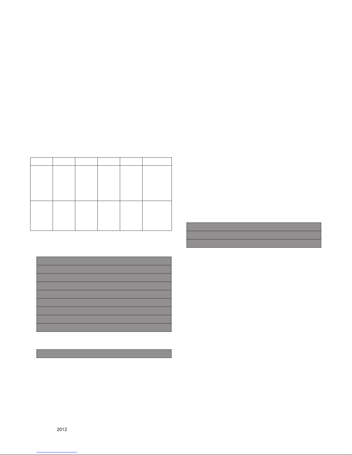
4.3. EDID DATA
4.3.1. North America (PCM)
4.3.1.1. HD Model
4.3.1.1.1. 8BIT
■ HDMI 1-HD (C/S : 71CF)
EDID Block 0, Bytes 0-127 [00H-7FH]
0 1 2 3 4 5 6 7 8 9 A B C D E F
---------------------------------------------------------------------------------
0 | 00 FF FF FF FF FF FF 00 1E 6D 01 00 01 01 01 01
10 | 01 16 01 03 80 A0 5A 78 0A EE 91 A3 54 4C 99 26
20 | 0F 50 54 A1 08 00 31 40 45 40 61 40 71 40 01 01
30 | 01 01 01 01 01 01 66 21 50 B0 51 00 1B 30 40 70
40 | 36 00 40 84 63 00 00 1E 64 19 00 40 41 00 26 30
50 | 18 88 36 00 40 84 63 00 00 1E 00 00 00 FD 00 3A
60 | 3E 1E 53 10 00 0A 20 20 20 20 20 20 00 00 00 FC
70 | 00 4C 47 20 54 56 0A 20 20 20 20 20 20 20 01 71
EDID Block 1, Bytes 128-255 [80H-FFH]
0 1 2 3 4 5 6 7 8 9 A B C D E F
---------------------------------------------------------------------------------
0 | 02 03 19 F1 48 10 22 20 05 84 03 02 01 23 09 57
10 | 07 67 03 0C 00 10 00 80 1E 02 3A 80 18 71 38 2D
20 | 40 58 2C 04 05 40 84 63 00 00 1E 01 1D 80 18 71
30 | 1C 16 20 58 2C 25 00 40 84 63 00 00 9E 01 1D 00
40 | 72 51 D0 1E 20 6E 28 55 00 40 84 63 00 00 1E 8C
50 | 0A D0 8A 20 E0 2D 10 10 3E 96 00 40 84 63 00 00
60 | 18 26 36 80 A0 70 38 1F 40 30 20 25 00 40 84 63
70 | 00 00 1A 00 00 00 00 00 00 00 00 00 00 00 00 CF
■ HDMI 2-HD (C/S : 71BF)
EDID Block 0, Bytes 0-127 [00H-7FH]
0 1 2 3 4 5 6 7 8 9 A B C D E F
---------------------------------------------------------------------------------
0 | 00 FF FF FF FF FF FF 00 1E 6D 01 00 01 01 01 01
10 | 01 16 01 03 80 A0 5A 78 0A EE 91 A3 54 4C 99 26
20 | 0F 50 54 A1 08 00 31 40 45 40 61 40 71 40 01 01
30 | 01 01 01 01 01 01 66 21 50 B0 51 00 1B 30 40 70
40 | 36 00 40 84 63 00 00 1E 64 19 00 40 41 00 26 30
50 | 18 88 36 00 40 84 63 00 00 1E 00 00 00 FD 00 3A
60 | 3E 1E 53 10 00 0A 20 20 20 20 20 20 00 00 00 FC
70 | 00 4C 47 20 54 56 0A 20 20 20 20 20 20 20 01 71
EDID Block 1, Bytes 128-255 [80H-FFH]]
0 1 2 3 4 5 6 7 8 9 A B C D E F
---------------------------------------------------------------------------------
0 | 02 03 19 F1 48 10 22 20 05 84 03 02 01 23 09 57
10 | 07 67 03 0C 00 20 00 80 1E 02 3A 80 18 71 38 2D
20 | 40 58 2C 04 05 40 84 63 00 00 1E 01 1D 80 18 71
30 | 1C 16 20 58 2C 25 00 40 84 63 00 00 9E 01 1D 00
40 | 72 51 D0 1E 20 6E 28 55 00 40 84 63 00 00 1E 8C
50 | 0A D0 8A 20 E0 2D 10 10 3E 96 00 40 84 63 00 00
60 | 18 26 36 80 A0 70 38 1F 40 30 20 25 00 40 84 63
70 | 00 00 1A 00 00 00 00 00 00 00 00 00 00 00 00 BF
4.3.2. AC3 EDID Data
4.3.2.1. HD Model
4.3.2.1.1. 8BIT
■ HDMI 1-HD (C/S : 715D)
EDID Block 0, Bytes 0-127 [00H-7FH]
0 1 2 3 4 5 6 7 8 9 A B C D E F
-------------------------------------------------------------------------------
0 | 00 FF FF FF FF FF FF 00 1E 6D 01 00 01 01 01 01
10 | 01 16 01 03 80 A0 5A 78 0A EE 91 A3 54 4C 99 26
20 | 0F 50 54 A1 08 00 31 40 45 40 61 40 71 40 01 01
30 | 01 01 01 01 01 01 66 21 50 B0 51 00 1B 30 40 70
40 | 36 00 40 84 63 00 00 1E 64 19 00 40 41 00 26 30
50 | 18 88 36 00 40 84 63 00 00 1E 00 00 00 FD 00 3A
60 | 3E 1E 53 10 00 0A 20 20 20 20 20 20 00 00 00 FC
70 | 00 4C 47 20 54 56 0A 20 20 20 20 20 20 20 01 71
EDID Block 1, Bytes 128-255 [80H-FFH]
0 1 2 3 4 5 6 7 8 9 A B C D E F
--------------------------------------------------------------------------------
0 | 02 03 1C F1 48 10 22 20 05 84 03 02 01 26 15 07
10 | 50 09 57 07 67 03 0C 00 10 00 80 1E 02 3A 80 18
20 | 71 38 2D 40 58 2C 04 05 40 84 63 00 00 1E 01 1D
30 | 80 18 71 1C 16 20 58 2C 25 00 40 84 63 00 00 9E
40 | 01 1D 00 72 51 D0 1E 20 6E 28 55 00 40 84 63 00
50 | 00 1E 8C 0A D0 8A 20 E0 2D 10 10 3E 96 00 40 84
60 | 63 00 00 18 26 36 80 A0 70 38 1F 40 30 20 25 00
70 | 40 84 63 00 00 1A 00 00 00 00 00 00 00 00 00 5D
■ HDMI 2-HD (C/S : 714D)
EDID Block 0, Bytes 0-127 [00H-7FH]
0 1 2 3 4 5 6 7 8 9 A B C D E F
-------------------------------------------------------------------------------
0 | 00 FF FF FF FF FF FF 00 1E 6D 01 00 01 01 01 01
10 | 01 16 01 03 80 A0 5A 78 0A EE 91 A3 54 4C 99 26
20 | 0F 50 54 A1 08 00 31 40 45 40 61 40 71 40 01 01
30 | 01 01 01 01 01 01 66 21 50 B0 51 00 1B 30 40 70
40 | 36 00 40 84 63 00 00 1E 64 19 00 40 41 00 26 30
50 | 18 88 36 00 40 84 63 00 00 1E 00 00 00 FD 00 3A
60 | 3E 1E 53 10 00 0A 20 20 20 20 20 20 00 00 00 FC
70 | 00 4C 47 20 54 56 0A 20 20 20 20 20 20 20 01 71
EDID Block 1, Bytes 128-255 [80H-FFH]
0 1 2 3 4 5 6 7 8 9 A B C D E F
--------------------------------------------------------------------------------
0 | 02 03 1C F1 48 10 22 20 05 84 03 02 01 26 15 07
10 | 50 09 57 07 67 03 0C 00 20 00 80 1E 02 3A 80 18
20 | 71 38 2D 40 58 2C 04 05 40 84 63 00 00 1E 01 1D
30 | 80 18 71 1C 16 20 58 2C 25 00 40 84 63 00 00 9E
40 | 01 1D 00 72 51 D0 1E 20 6E 28 55 00 40 84 63 00
50 | 00 1E 8C 0A D0 8A 20 E0 2D 10 10 3E 96 00 40 84
60 | 63 00 00 18 26 36 80 A0 70 38 1F 40 30 20 25 00
70 | 40 84 63 00 00 1A 00 00 00 00 00 00 00 00 00 4D
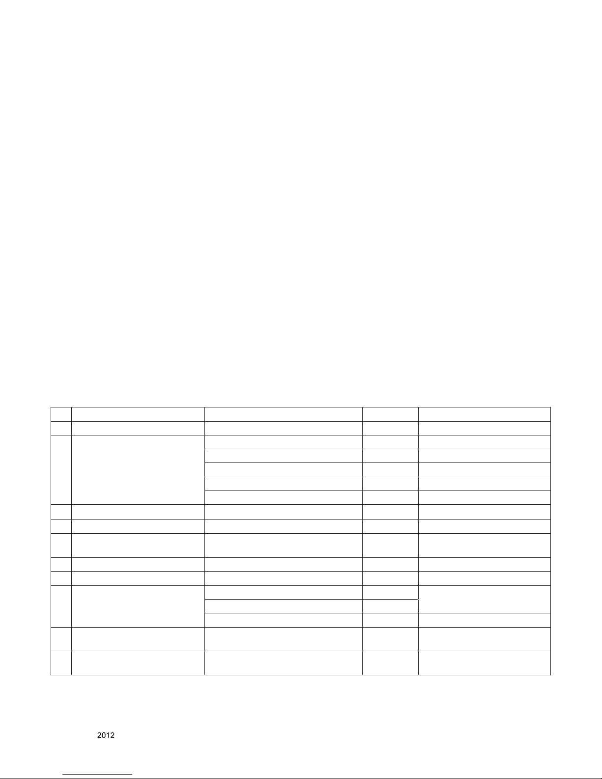
4.4. Tool Option Input
- Input Model Tool Option according to BOM