LG 29eb53 User manual

www.lg.com
Owner's Manual
IPS LED MONITOR
(LED MONITOR)
29EB53
Please read the safety information carefully before using the
product.
IPS LED Monitor (LED Monitor) Model List
ENGLISH

2
ENG
ENGLISH
Contents
CONTENTS
23 INSTALLING LG MONITOR
SOFTWARE
26 CUSTOMIZING SETTINGS
26 ActivatingtheMainMenu
27 Customizingsettings
27 - MenuSettings
28 - RatioSettings
29 - Func.Settings
30 - PBPsettings
31 - Picture
32 - Color
33 - Settings
34 TROUBLESHOOTING
36 SPECIFICATIONS
37 Factorysupportmode
(PresetMode,DVI-D/HDMI/PC
DisplayPort)
37 HDMI/MHLTiming(Video)
37 PowerIndicator
38 PROPER POSTURE
38 ProperPostureforUsingtheMonitor
3 LICENSE
4 ASSEMBLING AND
PREPARING
4 ProductComponents
5 ComponentandButtonDescription
7 MovingandLiftingtheMonitor
8 InstallingtheMonitor
8 - Assemblingthestandbase
10 - Detachingthestandbase
12 - Installingontoatable
13 - Adjustingthestandheight
14 - Adjustingtheangle
15 - Tidyingcables
15 - UsingtheKensingtonlock
16 - Installingthewallmountplate
16 - Installingtoawall
18 USING THE MONITOR
18 ConnectingtoaPC
18 - DVIconnection
19 - DisplayPortconnection
19 - HDMIconnection
20 ConnectingtoAVDevices
20 - HDMIconnection
20 ConnectingtoExternalDevices
20 - Smartphone(MHL)connection
21 - USBcable-PCconnection
22 - Headphoneportconnection

3
ENG
ENGLISH
LICENSE
LICENSE
Eachmodelhasdifferentlicenses.Visitwww.lg.comformoreinformationonthelicense.
ThetermsHDMIandHDMIHigh-DefinitionMultimediaInterface,andthe
HDMIlogoaretrademarksorregisteredtrademarksofHDMILicensingLLC
intheUnitedStatesandothercountries.
VESA,VESAlogo,DisplayPortComplianceLogoandDisplayPort
ComplianceLogofordual-modesourceareallregisteredtrademarksofthe
VideoElectronicsStandardsAssociation.

4
ENG
ENGLISH
ASSEMBLING AND PREPARING
Product Components
Pleasecheckwhetherallthecomponentsareincludedintheboxbeforeusingtheproduct.Ifthereare
missingcomponents,contacttheretailstorewhereyoupurchasedtheproduct.Notethattheproductand
componentsmaylookdifferentfromthoseshownhere.
Alwaysusegenuinecomponentstoensuresafetyandproductperformance.
Theproductwarrantywillnotcoverdamageorinjurycausedbytheuseofcounterfeitcomponents.
Notethatthecomponentsmaylookdifferentfromthoseshownhere.
Withoutpriornotice,allinformationandspecificationsinthismanualaresubjecttochangetoim-
provetheperformanceoftheproduct.
Topurchaseoptionalaccessories,visitanelectronicsstoreoronlineshoppingsiteorcontactthe
retailstorewhereyoupurchasedtheproduct.
TheDisplayPortcablemaynotbeavailableinsomeareas.
CAUTION
NOTE
Power Cord
Audio Cable
User Manual/Card AC/DC Adapter DVI-D Dual Cable
OPTIONAL ACCESSORIES
TheDisplayPortcablemaynot
beavailableinsomeareas.
Display Port Cable
Stand Base One Screw Cable Holder
A-B Type USB 3.0 Cable
or
Two Screws
Stand Body

5
ENG
ENGLISH
ASSEMBLING AND PREPARING
Component and Button Description
DVI-D IN
HDMI 1
HDMI 2/MHL
AUDIO IN(PC)
5 V 0.9 A
DP IN
H/P
Ports
5 V 0.9 A
5 V 0.5 A
DC-IN (19 V )
USB IN 1 USB IN 2
USB IN 3
USB UP
/PBP
Power Indicator
On:powerison
Off:powerisoff
Touchbuttonsonthebottom
ofthemonitor
(PowerButton)

6
ENG
ENGLISH
ASSEMBLING AND PREPARING
Moving and Lifting the Monitor
Whenmovingorliftingthemonitor,followthese
instructionstopreventthemonitorfrombeing
scratchedordamagedandtoensuresafetrans-
portationregardlessofitsshapeorsize.
Asfaraspossible,avoidtouchingthemoni-
torscreen.Thismayresultindamagetothe
screenorsomeofthepixelsusedtocreate
images.
Itisadvisabletoplacethemonitorinthe
originalboxorpackingmaterialbeforeat-
temptingtomoveit.
Beforemovingorliftingthemonitor,discon-
nectthepowercordandallcables.
Holdthetopandbottomofthemonitorframe
firmly.Donotholdthepanelitself.
Whenholdingthemonitor,thescreenshould
faceawayfromyoutopreventitbeing
scratched.
Whenmovingthemonitor,avoidanystrong
shockorvibrationstotheproduct.
Whenmovingthemonitor,keepitupright,
neverturnthemonitoronitssideortiltit
sideways.
29EB53
CAUTION

7
ENG
ENGLISH
ASSEMBLING AND PREPARING
Installing the Monitor
Assembling the stand base
Stand Body
Stand Base
1Place the Monitor set with the screen side
down on a flat and cushioned surface.
4Using a coin, turn the screw clockwise to se-
cure the stand base.
CAUTION
y
To protect the screen from scratches, cover
the surface with a soft cloth.
3Check the position (at the front and rear) of
the stand body, then mount the stand base on
the stand body as shown in the figure.
Stand Base
2Use a tool to attach the stand body as shown
in the figure.
Stand Body

8
ENG
ENGLISH
ASSEMBLING AND PREPARING
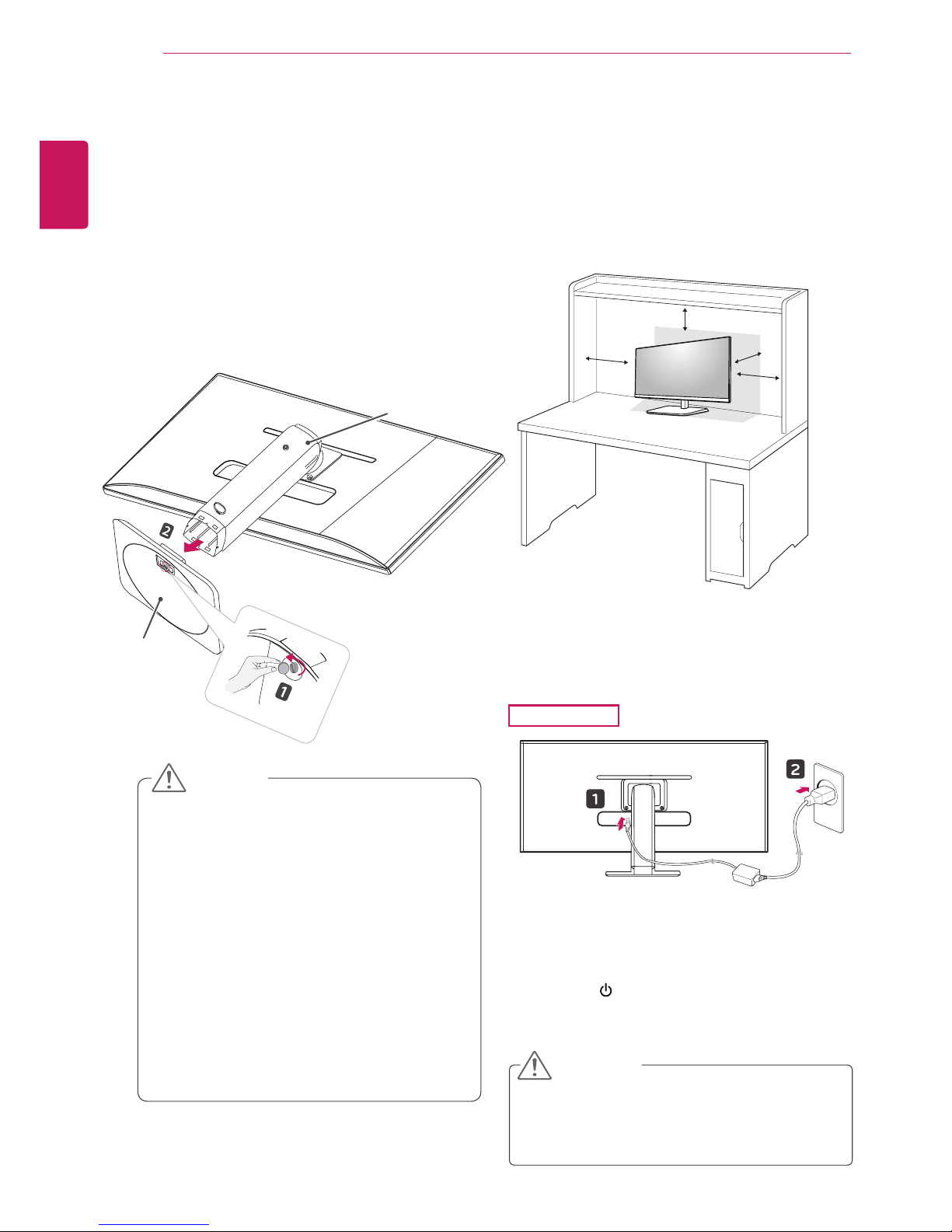
Installing onto a table
1 Liftthemonitorandplaceitonthetableinan
uprightposition.
Placeatleast10 cmawayfromthewallto
ensuresufficientventilation.
2 Connecttheadaptertothemonitor,thenplug
thepowercordintothepoweroutlet.
3 Pressthe (Power)buttononthebottomof
themonitortoturniton.
Unplugthepowercordpriortomovingor
installingthemonitor.Thereisriskofelectric
shock.
CAUTION
10cm
10cm
10cm
10cm
29EB53
y
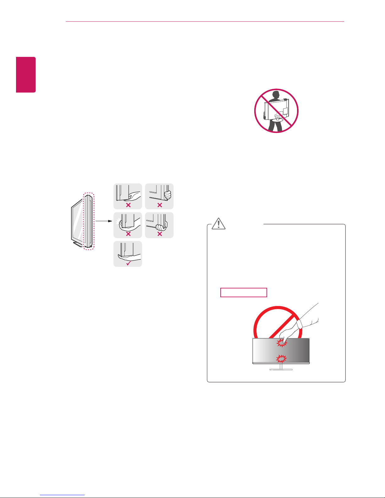
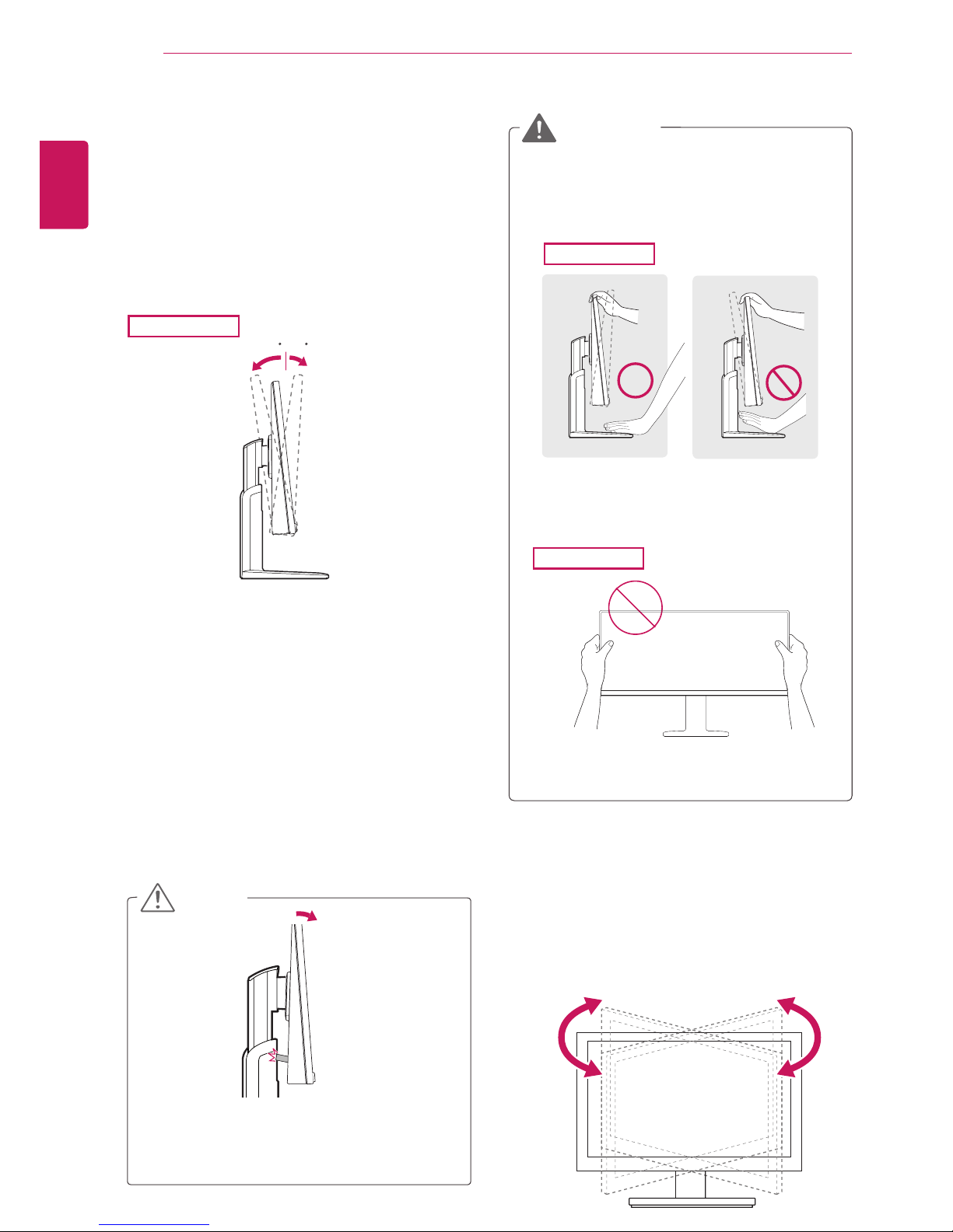
The components appearing in the illustra-
tions may look different from the actual prod-
uct.
y
Do not carry the monitor upside-down as this
may cause it to fall off its stand, resulting in
damage or injury.
y
To avoid damaging the screen when lifting
or moving the monitor, only hold the stand or
the plastic cover. This avoids putting unnec-
essary pressure on the screen.
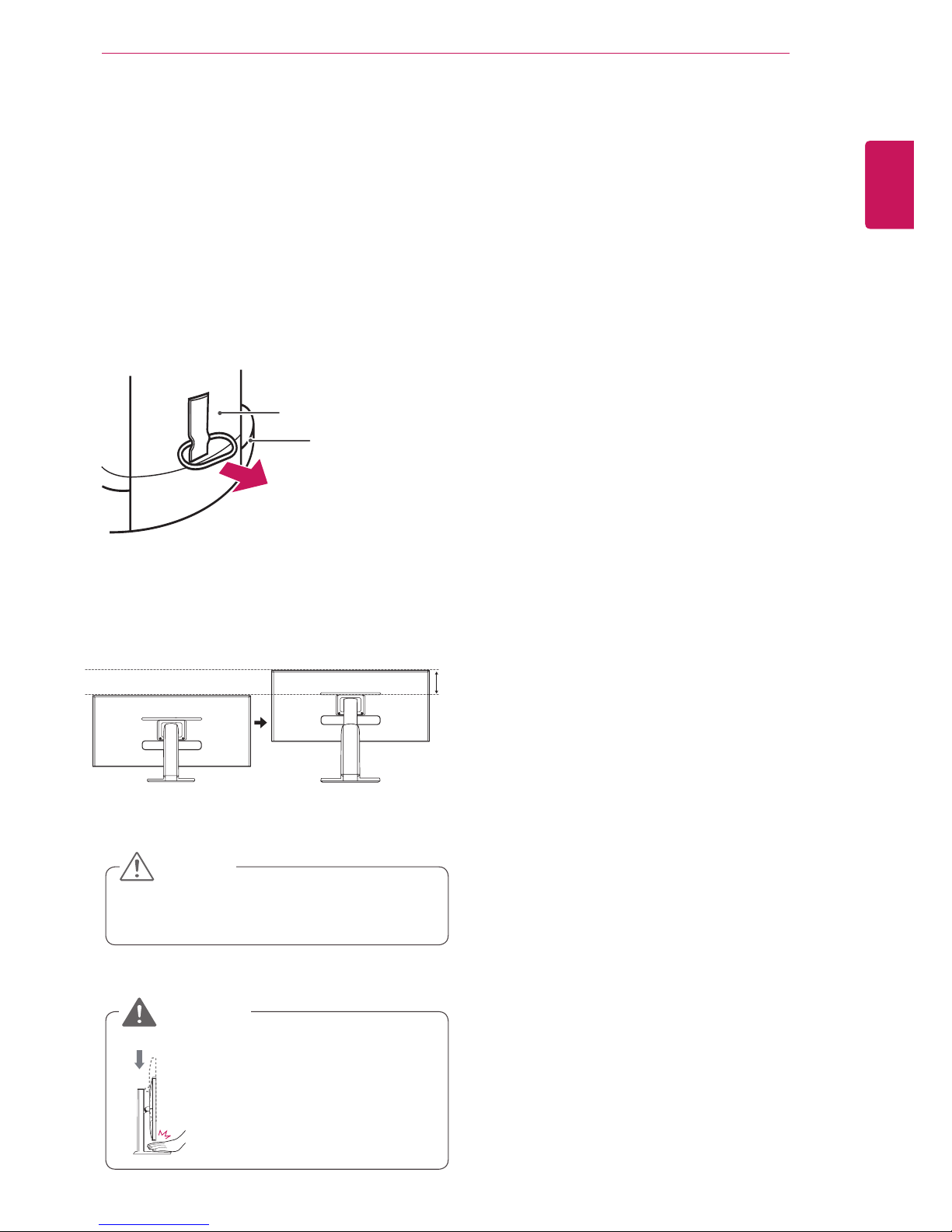
y
Only remove the tape and the locking pin
when the monitor is mounted on the stand
base and is in an upright position. Otherwise,
the stand body may protrude, which may
lead to injury.
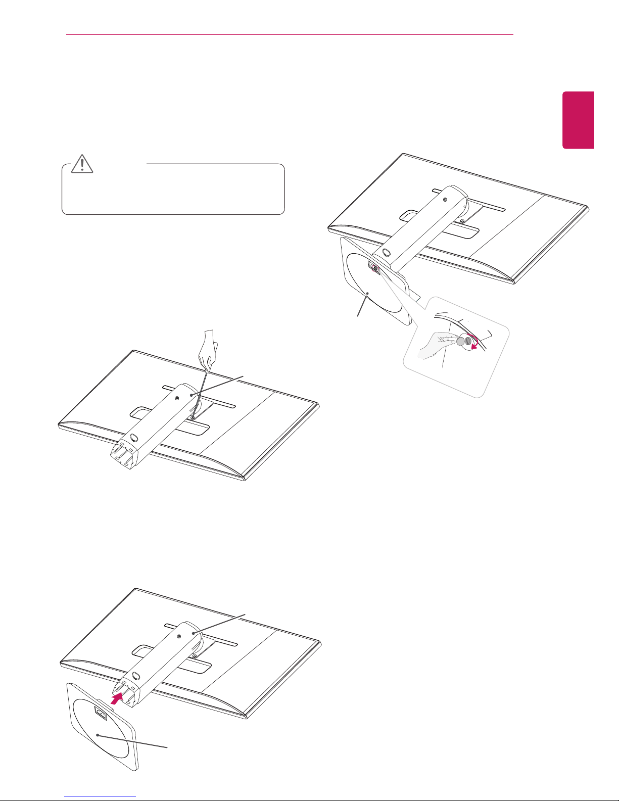
Detaching the stand base
1Place the monitor's screen face down.
To protect the screen from scratches, cover the
surface with a soft cloth.
2Using a coin, turn the screw in the stand base
counterclockwise. Detach the stand base from
the stand body.
CAUTION
Stand Base
Stand Body

9
ENG
ENGLISH
ASSEMBLING AND PREPARING
Oncethepinisremoved,itisnotnecessary
tore-insertittoadjusttheheight.
Adjusting the stand height
Donotputyourfingersor
handbetweenthescreen
andthebase(chassis)when
adjustingthescreen'sheight.
CAUTION
WARNING
120.0 mm
1Place the monitor mounted on the stand base
in an upright position.
2Remove the tape attached at the bottom rear
of the stand body, then pull out the locking
pin.
3The height can be adjusted up to 120 mm.
Tape
Locking Pin
Stand Body

10
ENG
ENGLISH
ASSEMBLING AND PREPARING
Adjusting the angle
1 Placethemonitorinanuprightposition,mount-
edonthestandbase.
2 Adjusttheangleofthescreen.Theangleof
thescreencanbeadjustedforwardsorback-
wardsfrom-5°to20°foracomfortableviewing
experience.
Toavoidinjurytothefingerswhenadjusting
thescreen,donotholdthelowerpartofthe
monitor'sframeasillustratedbelow.
Becarefulnottotouchorpressthescreen
areawhenadjustingtheangleofthemonitor.
WARNING
02 5-
Front Side
Rear Side
29EB53
Asshowninthepicture,becarefulnotto
lettheUSBbumpintothestandwhenyou
adjustthemonitor'sanglewiththeUSB
inserted.
NOTE
29EB53
-520
-520
29EB53
-520
-520
Swivel stand
yImage shown may differ from your Monitor
set.
1Swivel 355 degrees and adjust the angle of the
Monitor set to suit your view.

11
ENG
ENGLISH
ASSEMBLING AND PREPARING
Using the Kensington lock
TheconnectorfortheKensingtonlockislocatedat
therearofthemonitor.
Formoreinformationoninstallationandusage,
refertotheKensingtonlockusermanualorvisit
thewebsiteathttp://www.kensington.com.
ConnectthemonitortothetablewiththeKensing-
tonlockcable.
UseoftheKensingtonlockisoptional.The
accessoriescanbepurchasedatyourlocal
electronicsstore.
NOTE
29EB53
Using the cable holder
1Fix the Knob (Cable holder) to the
Hole(Hingebody).
2Use one screw to fix the Cable Holder and
monitor set.
3Close the Cable holder.

12
ENG
ENGLISH
ASSEMBLING AND PREPARING
Installing the wall mount plate
Thismonitorsupportsthespecificationofthestan-
dardwallmountplateorcompatibledevice.
1 Placethescreenfacedown.Toprotectthe
screenfromscratches,coverthesurfacewitha
softcloth.
2 Placethewallmountplateontothemonitor
andalignitwiththescrewholes.
3 Usingascrewdriver,tightenthefourscrewsto
fixtheplateontothemonitor.
Thewallmountplateissoldseparately.
Formoreinformationoninstallation,referto
thewallmountplate'sinstallationguide.
Becarefulnottouseexcessiveforcewhen
mountingthewallmountplate,asthiscan
damagethemonitor'sscreen.
Wall Mount Plate
NOTE
Toinstallthemonitortoawall,attachawallmount-
ingbracket(optional)tothebackofthemonitor.
Makesurethatthewallmountingbracketissecurely
fixedtothemonitorandtothewall.
1Usethescrewsandwallmountingbracketthat
complywiththeVESAstandard.
2Screwswhicharelongerthanthestandard
lengthmaydamagetheinsideofthemonitor.
3Anon-VESAstandardscrewmaydamagethe
productandcausethemonitortofall.LGElec-
tronicsisnotliableforanyaccidentsrelatingto
theuseofnon-standardscrews.
4ThemonitorisVESAstandardcompliant.
5UseitaccordingtotheVESAstandardasspeci-
fiedbelow.
784.8mmorless
*Thicknessofthewallmountplate:2.6mm
*Fasteningscrew:Diameter4.0mmxPitch0.7
mmxLength10mm
787.4mmorgreater
*
Usethewallmountplateandscrewsthatcon-
formtotheVESAstandard
.
Installing to a wall
Installthemonitoratleast10cmawayfromthe
wallandleaveabout10cmofspaceateachside
ofthemonitortoensuresufficientventilation.De-
tailedinstallationinstructionscanbeobtainedfrom
yourlocalretailstore.Pleaserefertothemanual
toinstallandsetupatiltingwallmountingbracket.
10cm
10cm
10cm
10cm

13
ENG
ENGLISH
ASSEMBLING AND PREPARING
Unplugthepowercordbeforemovingorin-
stallingthemonitortoavoidelectricshocks.
Installingthemonitorontheceilingorona
slantedwallmayresultinthemonitorfalling
off,whichcouldleadtoinjury.Pleaseuse
thegenuineLGwallmountingbracket.For
moreinformation,contactyourlocalretail
storeoraqualifiedinstaller.
Applyingexcessiveforcewhenfastening
screwsmaycausedamagetothemoni-
tor.Damagecausedinthiswaywillnotbe
coveredbytheproductwarranty.
Usethewallmountingbracketandscrews
thatconformtotheVESAstandard.Dam-
agecausedbytheuseormisuseofinap-
propriatecomponentswillnotbecovered
bytheproductwarranty.
UsethescrewsspecifiedbytheVESAstan-
dard.
Thewallmountkitincludestheinstallation
guideandallnecessaryparts.
Thewallmountingbracketisoptional.The
accessoriescanbepurchasedatyourlocal
retailstore.
Thelengthofthescrewmaydifferforeach
wallmountingbracket.Ensurethecorrect
lengthscrewisused.
Formoreinformation,pleaserefertothe
usermanualforthewallmountingbracket.
CAUTION
NOTE
VESA (A x B) 100x100
Stand Screw M4
Required Screws 4
Wall Mount Plate
(Optional)
RW120

14
ENG
ENGLISH
USING THE MONITOR
USING THE MONITOR
Connecting to a PC
Thismonitorsupportsthe*PlugandPlay
feature.
*PlugandPlay:Afeaturethatallowsyouto
addadevicetoyourcomputerwithouthaving
toreconfigureanythingorinstallanymanual
drivers.
DVI connection
Transmitsdigitalvideosignalstothemonitor.Con-
nectthemonitorusingtheDVIcableasillustrated
below.
Pressthemenu( )buttonandthenselectthe
inputoptionfromtheinputmenu.
TohearthesoundinDVIinputmode,connectthe
PC'sAUDIOOUTporttothemonitor'sAUDIOIN
(PC)portusingtheaudiocablethatcamewiththe
product.
Connecttheinputsignalcableand
turninthedirectionofthearrow.
Topreventdisconnectionsecure
thecabletightly.
Donotpressonthescreenfora
prolongedperiodoftime.Thismaycause
imagedistortion.
Donotdisplayastillimageonthescreen
foraprolongedperiodoftime.Thismay
causeimageretention.Ifpossible,usethe
screensaver.
CAUTION
Whenconnectingthepowercordtotheout-
let,useagrounded(3-hole)multi-socketora
groundedpoweroutlet.
Themonitormayflickerwhenturnedoninan
areaoflowtemperature.Thisisnormal.
Sometimesred,green,orbluespotsmayap-
pearonthescreen.Thisisnormal.
UsingaDVItoHDMIcablemaycausecom-
patibilityissues.
NOTE
DP OUT
DVI-D IN
H
DMI
1
H
DMI 2
/
AUDIO IN(PC)
5 V 0.9 A
5 V 0.5 A
5 V 0.9 A
D
P I
N
H
/
P
B IN
2
B IN
3
DVI-I(D) OUT
PC
AUDIO OUT
PC
MH
L
US
B IN
1
US
US
US
B
U
P
DVI
-
D
IN
H
DMI
1
H
DMI 2
/
MH
L
A
UDIO IN
(
PC
)
5 V 0.9 A
5 V 0.5 A
5 V 0.9 A
D
P I
N
H/P
US
B IN 1
US
B IN 2
US
B IN
3
US
B UP
DVI
-
D
IN
H
DMI
1
H
DMI 2
/
MHL
A
UDIO IN
(
PC
)
5 V 0.9 A
5 V 0.5 A
5 V 0.9 A
DP IN
H/P
US
B IN 1
US
B IN 2
US
B IN
3
US
B UP
DVI
-
D
IN
HDMI 1
HDMI 2/MHL
A
UDIO IN
(
PC
)
5 V 0.9 A
5 V 0.5 A
5 V 0.9 A
DP
IN
H/P
US
B IN
1
US
B IN 2
US
B IN
3
US
B UP
DVI
-
D
IN
H
DMI
1
HDMI 2/MHL
A
UDIO IN
(
PC
)
5 V 0.9 A
5 V 0.5 A
5 V 0.9 A
D
P I
N
H
/
P
US
B IN
1
US
B IN 2
US
B IN
3
USB UP
DVI-D I
N
HDMI
1
H
DMI 2
/
MHL
A
UDIO IN
(
PC
)
5 V 0.9 A
5 V 0.5 A
5 V 0.9 A
DP
IN
H/P
USB IN 1 USB IN 2
USB IN 3
USB UP

15
ENG
ENGLISH
USING THE MONITOR
Theremaybenovideooraudiooutputde-
pendingontheDPversionofthePC.
TheDisplayPortcablemaynotbeavailable
insomeareas.
DisplayPort connection
Transmitsthedigitalvideoandaudiosignalsfrom
yourPCtothemonitor.ConnectyourPCtothe
monitorusingthedisplayportcableasillustrated
below.
Pressthemenu( )buttonandthenselectthe
inputoptionfromtheinputmenu.
NOTE
(soldseparately)
DVI
-
D
IN
H
DMI
1
H
DMI 2
AUDIO IN(PC)
5 V 0.9 A
DP IN
H/P
DVI
-
D
IN
HDMI 1
HDMI 2/MHL
A
UDIO IN
(
PC
)
5 V 0.9 A
DP
IN
H/P
DP OUT
DVI-D IN
H
DMI
1
H
DMI 2
/
MH
L
AUDIO IN(PC)
5 V 0.9 A
5 V 0.5 A
5 V 0.9 A
D
P I
N
H
/
P
US
B IN
1
US
B IN 2
US
B IN
3
US
B
U
P
DVI-I(D) OUT
PC
DVI
-
D
IN
H
DMI
1
H
DMI 2
/
MH
L
A
UDIO IN
(
PC
)
5 V 0.9 A
5 V 0.5 A
5 V 0.9 A
D
P I
N
H/P
US
B IN 1
US
B IN 2
US
B IN
3
US
B UP
AUDIO OUT
PC
/
MHL
5 V 0.9 A
5 V 0.5 A
US
B IN 1
US
B IN 2
US
B IN
3
US
B UP
DVI
-
D
IN
HDMI 1
HDMI 2/MHL
A
UDIO IN
(
PC
)
5 V 0.9 A
5 V 0.5 A
5 V 0.9 A
DP
IN
H/P
US
B IN
1
US
B IN 2
US
B IN
3
US
B UP
DVI
-
D
IN
H
DMI
1
HDMI 2/MHL
A
UDIO IN
(
PC
)
5 V 0.9 A
5 V 0.5 A
5 V 0.9 A
D
P I
N
H
/
P
US
B IN
1
US
B IN 2
US
B IN
3
USB UP
DVI-D I
N
HDMI
1
H
DMI 2
/
MHL
A
UDIO IN
(
PC
)
5 V 0.9 A
5 V 0.5 A
5 V 0.9 A
DP
IN
H/P
USB IN 1 USB IN 2
USB IN 3
USB UP
HDMI connection
Transmitsthedigitalvideoandaudiosignalsfrom
yourPCandA/Vdevicestothemonitor.Connect
yourPCandAVdevicetothemonitorwiththe
HDMIcableasillustratedbelow.
Pressthemenu( )buttonandthenselectthe
inputoptionfromtheinputmenu.
(soldseparately)
HDMIPCmaycausedevicecompatibility
issues.
UsingaDVItoHDMIcablemaycausecom-
patibilityissues.
NOTE
DP OUT
DVI-D IN
H
DMI
1
H
DMI 2
/
MH
L
AUDIO IN(PC)
5 V 0.9 A
5 V 0.5 A
5 V 0.9 A
D
P I
N
H
/
P
US
B IN
1
US
B IN 2
US
B IN
3
US
B
U
P
DVI-I(D) OUT
PC
DVI
-
D
IN
H
DMI
1
H
DMI 2
/
MH
L
A
UDIO IN
(
PC
)
5 V 0.9 A
5 V 0.5 A
5 V 0.9 A
D
P I
N
H/P
US
B IN 1
US
B IN 2
US
B IN
3
US
B UP
AUDIO OUT
PC
DVI
-
D
IN
H
DMI
1
H
DMI 2
/
MHL
A
UDIO IN
(
PC
)
5 V 0.9 A
5 V 0.5 A
5 V 0.9 A
DP IN
H/P
US
B IN 1
US
B IN 2
US
B IN
3
US
B UP
5 V 0.9 A
5 V 0.5 A
US
B IN
1
US
B IN 2
US
B IN
3
US
B UP
DVI
-
D
IN
H
DMI
1
HDMI 2/MHL
A
UDIO IN
(
PC
)
5 V 0.9 A
5 V 0.5 A
5 V 0.9 A
D
P I
N
H
/
P
US
B IN
1
US
B IN 2
US
B IN
3
USB UP
DVI-D I
N
HDMI
1
H
DMI 2
/
MHL
A
UDIO IN
(
PC
)
5 V 0.9 A
5 V 0.5 A
5 V 0.9 A
DP
IN
H/P
USB IN 1 USB IN 2
USB IN 3
USB UP

16
ENG
ENGLISH
USING THE MONITOR
Connecting to AV Devices
HDMI connection
Transmitsthedigitalvideoandaudiosignalsfrom
yourPCandA/Vdevicestothemonitor.Connect
yourPCandAVdevicetothemonitorwiththe
HDMIcableasillustratedbelow.
Pressthemenu( )buttonandthenselectthe
inputoptionfromtheinputmenu.
UsingaDVItoHDMIcablemaycausecom-
patibilityissues.
NOTE
(soldseparately)
Thisfunctiononlyworksforsmartphones
thatsupportMHL.
-Theremaybecompatibilityissueswith
othermobilephones.
NOTE
Connecting to External Devices
Smartphone (MHL) connection
Mobile High-definition Link (MHL)isaninter-
facethatallowsyoutoplayvideoandaudiofrom
yoursmartphoneonthemonitorbyconnectingthe
monitortoyoursmartphone.Connectthesmart-
phonetotheHDMI2/MHLportofthemonitorusing
thesuppliedMHL signal cableandswitchthe
inputbypressingtheinputbuttononthemonitor.
DVI
-
D
IN
HDMI 1
HDMI 2/MHL
A
UDIO IN
(
PC
)
5 V 0.9 A
DP
IN
H/P
DVI
-
D
IN
H
DMI
1
HDMI 2/MHL
UDIO IN
(
PC
)
5 V 0.9 A
D
P I
N
H/P
DP OUT
DVI-D IN
H
DMI
1
H
DMI 2
/
MH
L
AUDIO IN(PC)
5 V 0.9 A
5 V 0.5 A
5 V 0.9 A
D
P I
N
H
/
P
US
B IN
1
US
B IN 2
US
B IN
3
US
B
U
P
DVI-I(D) OUT
PC
DVI
-
D
IN
H
DMI
1
H
DMI 2
/
MH
L
A
UDIO IN
(
PC
)
5 V 0.9 A
5 V 0.5 A
5 V 0.9 A
D
P I
N
H/P
US
B IN 1
US
B IN 2
US
B IN
3
US
B UP
AUDIO OUT
PC
DVI
-
D
IN
H
DMI
1
H
DMI 2
/
MHL
A
UDIO IN
(
PC
)
5 V 0.9 A
5 V 0.5 A
5 V 0.9 A
DP IN
H/P
US
B IN 1
US
B IN 2
US
B IN
3
US
B UP
5 V 0.9 A
5 V 0.5 A
US
B IN
1
US
B IN 2
US
B IN
3
US
B UP
DVI
-
D
IN
H
DMI
1
HDMI 2/MHL
A
UDIO IN
(
PC
)
5 V 0.9 A
5 V 0.5 A
5 V 0.9 A
D
P I
N
H
/
P
US
B IN
1
US
B IN 2
US
B IN
3
USB UP
DVI-D I
N
HDMI
1
H
DMI 2
/
MHL
A
UDIO IN
(
PC
)
5 V 0.9 A
5 V 0.5 A
5 V 0.9 A
DP
IN
H/P
USB IN 1 USB IN 2
USB IN 3
USB UP
DP OUT
DVI-D IN
H
DMI
1
H
DMI 2
/
MH
L
AUDIO IN(PC)
5 V 0.9 A
5 V 0.5 A
5 V 0.9 A
D
P I
N
H
/
P
US
B IN
1
US
B IN 2
US
B IN
3
US
B
U
P
DVI-I(D) OUT
PC
DVI
-
D
IN
H
DMI
1
H
DMI 2
/
MH
L
A
UDIO IN
(
PC
)
5 V 0.9 A
5 V 0.5 A
5 V 0.9 A
D
P I
N
H/P
US
B IN 1
US
B IN 2
US
B IN
3
US
B UP
AUDIO OUT
PC
DVI
-
D
IN
H
DMI
1
H
DMI 2
/
MHL
A
UDIO IN
(
PC
)
5 V 0.9 A
5 V 0.5 A
5 V 0.9 A
DP IN
H/P
US
B IN 1
US
B IN 2
US
B IN
3
US
B UP
DVI
-
D
IN
HDMI 1
HDMI 2/MHL
A
UDIO IN
(
PC
)
5 V 0.9 A
5 V 0.5 A
5 V 0.9 A
DP
IN
H/P
US
B IN
1
US
B IN 2
US
B IN
3
US
B UP
A
5 V 0.9 A
5 V 0.5 A
H
/
US
B IN
1
US
B IN 2
US
B IN
3
USB UP
DVI-D I
N
HDMI
1
H
DMI 2
/
MHL
A
UDIO IN
(
PC
)
5 V 0.9 A
5 V 0.5 A
5 V 0.9 A
DP
IN
H/P
USB IN 1 USB IN 2
USB IN 3
USB UP
(soldseparately)

17
ENG
ENGLISH
USING THE MONITOR
USB cable-PC connection
TheUSB3.0functionactsasaUSBhubonthe
product.
TouseUSB3.0,connecttheA-BtypeUSB3.0
cablefortheproducttothePC.
PeripheraldevicesconnectedtotheUSBINport
canbecontrolledfromthePC.
PleaseinstallthelatestWindowsservice
packbeforeuse.
Peripheraldevicesaresoldseparately.
TheUSBportscanbeusedtoconnectthe
keyboard,mouse,andotherUSBdevices.
NOTE
<CautionsWhenUsingaUSBDevice>
AUSBdevicewithanautomaticrecognition
programinstalled,orusingitsowndriver,
maynotberecognized.
SomeUSBdevicesmaynotbesupported
ormaynotworkproperly.
ItisrecommendedtouseaUSBhubor
harddiskdrivewithpowersupplied.(Ifthe
powersupplyisnotadequate,theUSB
devicemaynotberecognizedproperly.)
CAUTION
(soldseparately)
5 V 0.9 A
5 V 0.5 A
USB IN 1 USB IN 2
USB IN 3
USB UP
DP OUT
DVI-D IN
H
DMI
1
H
DMI 2
/
MH
L
AUDIO IN(PC)
5 V 0.9 A
5 V 0.5 A
5 V 0.9 A
D
P I
N
H
/
P
US
B IN
1
US
B IN 2
US
B IN
3
US
B
U
P
DVI-I(D) OUT
PC
DVI
-
D
IN
H
DMI
1
H
DMI 2
/
MH
L
A
UDIO IN
(
PC
)
5 V 0.9 A
5 V 0.5 A
5 V 0.9 A
D
P I
N
H/P
US
B IN 1
US
B IN 2
US
B IN
3
US
B UP
AUDIO OUT
PC
DVI
-
D
IN
H
DMI
1
H
DMI 2
/
MHL
A
UDIO IN
(
PC
)
5 V 0.9 A
5 V 0.5 A
5 V 0.9 A
DP IN
H/P
US
B IN 1
US
B IN 2
US
B IN
3
US
B UP
DVI
-
D
IN
HDMI 1
HDMI 2/MHL
A
UDIO IN
(
PC
)
5 V 0.9 A
5 V 0.5 A
5 V 0.9 A
DP
IN
H/P
US
B IN
1
US
B IN 2
US
B IN
3
US
B UP
DVI
-
D
IN
H
DMI
1
HDMI 2/MHL
A
UDIO IN
(
PC
)
5 V 0.9 A
5 V 0.5 A
5 V 0.9 A
D
P I
N
H
/
P
US
B IN
1
US
B IN 2
US
B IN
3
USB UP
DVI-D I
N
HDMI
1
H
DMI 2
/
MHL
(
PC
)
5 V 0.9 A
DP
IN

18
ENG
ENGLISH
USING THE MONITOR
5 V 0.9 A
5 V 0.5 A
H/P
US
B IN 1
US
B IN 2
US
B IN
3
US
B UP
(sold separately)
DP OUT
DVI-D IN
H
DMI
1
H
DMI 2
/
MH
L
AUDIO IN(PC)
5 V 0.9 A
5 V 0.5 A
5 V 0.9 A
D
P I
N
H
/
P
US
B IN
1
US
B IN 2
US
B IN
3
US
B
U
P
DVI-I(D) OUT
PC
DVI
-
D
IN
H
DMI
1
H
DMI 2
/
MH
L
5 V 0.9 A
D
P I
N
AUDIO OUT
PC
DVI
-
D
IN
H
DMI
1
H
DMI 2
/
MHL
A
UDIO IN
(
PC
)
5 V 0.9 A
5 V 0.5 A
5 V 0.9 A
DP IN
H/P
US
B IN 1
US
B IN 2
US
B IN
3
US
B UP
DVI
-
D
IN
HDMI 1
HDMI 2/MHL
A
UDIO IN
(
PC
)
5 V 0.9 A
5 V 0.5 A
5 V 0.9 A
DP
IN
H/P
US
B IN
1
US
B IN 2
US
B IN
3
US
B UP
DVI
-
D
IN
H
DMI
1
HDMI 2/MHL
A
UDIO IN
(
PC
)
5 V 0.9 A
5 V 0.5 A
5 V 0.9 A
D
P I
N
H
/
P
US
B IN
1
US
B IN 2
US
B IN
3
USB UP
DVI-D I
N
HDMI
1
H
DMI 2
/
MHL
A
UDIO IN
(
PC
)
5 V 0.9 A
5 V 0.5 A
5 V 0.9 A
DP
IN
H/P
USB IN 1 USB IN 2
USB IN 3
USB UP
Headphone port connection
Usetheheadphoneporttoconnectaperipheral
devicetothemonitor.Connectasillustrated.
DependingontheaudiosettingsofthePC
andexternaldevice,headphoneandspeaker
functionsmaybelimited.
NOTE
Foranangleplugearphone,itisdifficult
connectitwithaperipheraldevice,sousea
straighttype.
NOTE
AngleType StraightType

19
ENG
ENGLISH
INSTALLING LG Monitor Software
INSTALLING LG MONITOR SOFTWARE
1 SetthedefaultWebbrowsertoInternetExplorer.
Insertthetheowner'smanualCDincludedintheproductpackageintoyourPC'sCDdriverandinstallthe
LGMonitorSoftware.
2
Clickthe"LGMonitorSoftware"ontheCD's
mainscreen.Whenthefiledownloadwindow
appears,clicktheRunbutton.(Thefiledown-
loadwindowmayvarydependingontheoper-
atingsystemandtheInternetExplorerversion,
buttheinstallationproceduresaresame.)
ServicePack1orhigherisrequiredfor
Window7.
3 Followtheinstructionstoproceedwiththe
installation.
4 Check"Iacceptthetermsoftheagreement"on
theLicenseAgreementscreenandthenclick
the[Next]button.
ScreenSplit:Thisprogramautomatically
splitstheprogramwindowasdesired.
TrueColorFinder:Thisprogramcalibrates
theprecisecoloroutputofthemonitortosuit
yourneeds.
AutoResolution:Thisisaprogramthat
automaticallychangestheresolutiontothe
optimalsettingswhenconnectingthemonitor
tothePCinPBPmode.
ThisprogramisnotsupportedinClone
Mode.
ExtendedModeisnotsupportedwhen
usingasingledisplay.
5
Selecttheprogramthatyouwanttoinstall.
NOTE
CAUTION

20
ENG
ENGLISH
INSTALLING LG Monitor Software
6
TheLGMonitorSoftwareinstallationstartsas
shownbelow.
8 TheprogramyouselectedontheSelect
Featurespagewillinstallautomatically.
9
Whentheinstallationiscomplete,restartyour
system.
7 IftheTUSB3410driverhasnotbeeninstalled,
itwillinstallautomatically.Select"Installthis
driversoftwareanyway(I)"iftheWindows
securitymessageisdisplayedasbelow.
This manual suits for next models
1
Table of contents
Other LG Monitor manuals