LG OLED48A2AUA User manual

ENGLISH_index
Safety and Reference
OWNER’S MANUAL
Please read this manual carefully before
operating your set and retain it for
future reference.
The model and serial number of the product are
located on the back and on one side of the product.
Record them below in case you ever need service.
Model
Serial No.
OLED48A2AUA
OLED48A2PUA
OLED55A2AUA
OLED55A2PUA
OLED65A2AUA
OLED65A2PUA
OLED77A2AUA
OLED77A2PUA
OLED55B2PUA
OLED65B2PUA
OLED77B2PUA
OLED42C2AUA
OLED42C2PUA
OLED48C2AUA
OLED48C2PUA
OLED55C2AUA
OLED55C2PUA
OLED65C2AUA
OLED65C2PUA
OLED77C2AUA
OLED77C2PUA
OLED83C2AUA
OLED83C2PUA
www.lg.com
Copyright © 2022 LG Electronics Inc.
All Rights Reserved.
Printed in Korea
*MFL718561332202REV00*
Supplier`s Declaration of
Conformity
Trade Name LG
Responsible
Party
LG Electronics USA,
Inc.
Address 111 Sylvan Avenue,
North Building,
Englewood Cliffs,
NJ07632
E-mail lg.environmental@
lge.com
LG Customer Information Center
For inquires or comments, visit www.
lg.com or call;
1-888-542-2623 CANADA
1-800-243-0000 USA, Consumer
User
1-888-865-3026 USA, Commercial
User
Register your product Online!
www.lg.com

OWNER’S MANUAL
EXTERNAL CONTROL
DEVICE SETUP
Please read this manual carefully before operating the set and retain it for
future reference.
www.lg.com
P/NO : MFL71445401 (1901-REV00)

2
ENG
ENGLISH
2KEY CODES
KEY CODES
• This feature is not available for all models.
Code
(Hexa) Function Note Code
(Hexa) Function Note
00 CH +, PR + R/C Button 53 List R/C Button
01 CH -, PR - R/C Button 5B Exit R/C Button
02 Volume + R/C Button 60 PIP(AD) R/C Button
03 Volume - R/C Button 61 Blue R/C Button
06 > (Arrow Key / Right Key) R/C Button 63 Yellow R/C Button
07 < (Arrow Key / Left Key) R/C Button 71 Green R/C Button
08 Power R/C Button 72 Red R/C Button
09 Mute R/C Button 79 Ratio / Aspect Ratio R/C Button
0B Input R/C Button 91 AD (Audio Description) R/C Button
0E SLEEP R/C Button 9E LIVE MENU R/C Button
0F TV, TV/RAD R/C Button 7A User Guide R/C Button
10 - 19 * Number Key 0 - 9 R/C Button 7C Smart / Home R/C Button
1A Q.View / Flashback R/C Button 7E SIMPLINK R/C Button
1E FAV (Favorite Channel) R/C Button 8E ►►(Forward) R/C Button
20 Text (Teletext) R/C Button 8F ◄◄(Rewind) R/C Button
21 T. Opt (Teletext Option) R/C Button AA Info R/C Button
28 Return (BACK) R/C Button AB Program Guide R/C Button
30 AV (Audio / Video) Mode R/C Button B0 ►(Play) R/C Button
39 Caption/Subtitle R/C Button B1 ꕗ(Stop / File List) R/C Button
40 Λ
(Arrow Key / Cursor Up)
R/C Button B5 RECENT R/C Button
41 V (Arrow Key / Cursor
Down) R/C Button BA ꕘ(Freeze / Slow Play /
Pause) R/C Button
42 My Apps R/C Button BB Soccer R/C Button
43 Menu / Settings R/C Button BD ꔄ(REC) R/C Button
44 OK / Enter R/C Button DC 3D R/C Button
45 Q.Menu R/C Button 99 AutoConfig R/C Button
4C List, - R/C Button 9F App / * R/C Button
4D PICTURE R/C Button 9B TV / PC R/C Button
52 SOUND R/C Button
* Key code 4C (0x4C) is available on ATSC/ISDB models which use major/minor channel.
(For South Korea, Japan, North America, Latin America except Colombia models)

3
ENGENGLISH
3
EXTERNAL CONTROL DEVICE SETUP
• Image shown may differ from your TV.
Connect the USB to Serial(RS-232C) converter/RS-232C(Serial) input jack to an external control device
(such as a computer or an A/V control system) to control the product’s functions externally.
Note: The type of control port on the TV can be different between model series.
* Please be advised that not all models support this type of connectivity.
* Cable is not provided.
USB to Serial(RS-232C) converter with USB Cable
USB Type
USB IN
(TV)
(PC)
(PC
)
RS-232C IN
(CONTROL & SERVICE)
(TV)
(TV)
(PC)
(TV)
(PC)
SERVICE ONLY
RS-232C IN
(CONTROL & SERVICE)
RS-232C IN
(CONTROL & SERVICE)
1
3
2
1
3
2
• LGTV supports PL2303 chip-based (Vendor ID : 0x0557, Product ID : 0x2008) USB to serial(RS-232C)
converter which is not made nor provided by LG.
• It can be purchased from computer stores that carry accessories for IT support professionals.
RS-232C(Serial) With RS-232C(Serial) Cable
DE9 (D-Sub 9pin) Type
• You need to purchase the RS-232C (DE9, D-Sub 9pin female-to-female type) to RS-232C(Serial) cable
required for the connection between the PC and the TV, which is specified in the manual.
USB IN
(TV)
(PC
)
(PC)
RS-232C IN
(CONTROL & SERVICE)
(TV)
(TV)
(PC)
(TV)
(PC)
SERVICE ONLY
RS-232C IN
(CONTROL & SERVICE)
RS-232C IN
(CONTROL & SERVICE)
1
3
2
1
3
2
The connection interface may differ from your TV.

4
ENG
ENGLISH
4EXTERNAL CONTROL DEVICE SETUP
Phone jack Type
• You need to purchase the phone-jack to RS-232 cable required for the connection between the PC and
the TV, which is specified in the manual.
* For other models, connect to the USB port.
* The connection interface may differ from your TV.
USB IN
(TV)
(PC)
(PC)
RS-232C IN
(CONTROL & SERVICE)
(TV)
(TV)
(PC
)
(TV)
(PC)
SERVICE ONLY
RS-232C IN
(CONTROL & SERVICE)
RS-232C IN
(CONTROL & SERVICE)
1
3
2
1
3
2
- or
USB IN
(TV)
(PC)
(PC)
RS-232C IN
(CONTROL & SERVICE)
(TV)
(TV)
(PC)
(TV)
(PC
)
SERVICE ONLY
RS-232C IN
(CONTROL & SERVICE)
RS-232C IN
(CONTROL & SERVICE)
1
3
2
1
3
2
Customer Computer RS-232C configurations
3-Wire Configurations(Not standard)
1
6
5
9
PC TV
RXD 2 2 TXD
TXD 3 1 RXD
GND 5 3 GND
OR
RXD 3 2 TXD
TXD 2 1 RXD
GND 5 3 GND
D-Sub 9 Phone
RS-232C
(Serial port)
Set ID
For Set ID number, see "Real Data Mapping" on p.6
1. Press SETTINGS to access the main menus.
2. Press the Navigation buttons to scroll to (*General → About this TV or OPTION) and press OK.
3. Press the Navigation buttons to scroll to SET ID and press OK.
4. Scroll left or right to select a set ID number and select CLOSE. The adjustment range is 1-99.
5. When you are finished, press EXIT.
* (Depending on model)

5
ENGENGLISH
5
EXTERNAL CONTROL DEVICE SETUP
Communication Parameters
• Baud rate : 9600 bps (UART)
• Data length : 8 bits
• Parity : None
• Stop bit : 1 bit
• Communication code : ASCII code
• Use a crossed (reverse) cable.
Command reference list
(Depending on model)
COMMAND1 COMMAND2 DATA
(Hexadecimal) COMMAND1 COMMAND2 DATA
(Hexadecimal)
01. Power* k a 00 to 01 15. Balance k t 00 to 64
02. Aspect
Ratio k c (p.7)
16. Color
(Colour)
Temperature
x u 00 to 64
03. Screen
Mute k d (p.7)
17. ISM
Method (Only
Plasma TV)
j p (p.8)
04. Volume
Mute k e 00 to 01 18. Equalizer j v (p.9)
05. Volume
Control k f 00 to 64 19. Energy
Saving j q 00 to 05
06. Contrast k g 00 to 64 20. Tune
Command m a (p.9)
07.
Brightness k h 00 to 64
21. Channel
(Programme)
Add/Del(Skip)
m b 00 to 01
08. Color/
Colour k i 00 to 64 22. Key m c Key Codes
09. Tint k j 00 to 64
23. Control
Backlight,
Control Panel
Light
m g 00 to 64
10.
Sharpness k k 00 to 32 24. Input
select (Main)
x b (p.11)
11. OSD
Select k l 00 to 01 25. 3D (Only
3D models)
x t (p.11)
12. Remote
Control Lock
Mode
k m 00 to 01
26. Extended
3D (Only 3D
models)
x v (p.12)
13. Treble k r 00 to 64
27. Auto
Configure
j u (p.12)
14. Bass k s 00 to 64
* Note: During playing or recording media, all commands except Power (ka) and Key (mc) are not
executed and treated as NG.
With RS232C cable, TV can communicate "ka command" in power-on or power-off status. but with
USB-to-Serial converter cable, the command works only if TV is on.

6
ENG
ENGLISH
6EXTERNAL CONTROL DEVICE SETUP
Transmission / Receiving Protocol
Transmission
[Command1][Command2][ ][Set ID][ ][Data][Cr]
[Command 1] : First command to control the TV. (j, k, m or x)
[Command 2] : Second command to control the TV.
[Set ID] : You can adjust the [Set ID] to choose desired monitor ID number in option menu.
Adjustment range in TV is 1 to 99. If [Set ID] value is selected to ‘0’, every connected set
can be controlled.
* [Set ID] is indicated as decimal (1 to 99) on menu and as Hexadecimal (0x00 to 0x63) on
transmission/receiving protocol.
[DATA] : To transmit command data (hexadecimal). Transmit ‘FF’ data to read status of command.
[Cr] : Carriage Return - ASCII code ‘0x0D’
[ ] : Space – ASCII code ‘0x20’
OK Acknowledgement
[Command2][ ][Set ID][ ][OK][Data][x]
* The set transmits ACK (acknowledgement) based on this format when receiving normal data. At this time,
if the data is data read mode, it indicates present status data. If the data is data write mode, it returns the
data of the PC computer.
Error Acknowledgement
[Command2][ ][Set ID][ ][NG][Data][x]
* The set transmits ACK (acknowledgement) based on this format when receiving abnormal data from
non-viable functions or communication errors.
Data 00: Illegal Code
Real data mapping (Hexadecimal bDecimal)
* When you enter the [data] in hexadecimal, refer to following conversion table.
* Channel Tune (ma) Command uses two-byte hexadecimal value([data]) to select channel number.
00 : Step 0 32 : Step 50 (Set ID 50) FE : Step 254
01 : Step 1 (Set ID 1) 33 : Step 51 (Set ID 51) FF : Step 255
... ... ...
0A : Step 10 (Set ID 10) 63 : Step 99 (Set ID 99) 01 00 : Step 256
... ... ...
0F : Step 15 (Set ID 15) C7 : Step 199 27 0E : Step 9998
10 : Step 16 (Set ID 16) C8 : Step 200 27 0F : Step 9999
... ... ...

7
ENGENGLISH
7
EXTERNAL CONTROL DEVICE SETUP
* Commands may work differently depending on model and signal.
01. Power (Command: k a)
►To control Power *On or Off of the set.
Transmission[k][a][ ][Set ID][ ][Data][Cr]
Data 00 : Power Off 01 : *Power On
Ack [a][ ][Set ID][ ][OK/NG][Data][x]
►To Show TV is Power On or *Off
Transmission [k][a][ ][Set ID][ ][FF][Cr]
Ack [a][ ][Set ID][ ][OK][Data][x]
* Similarly, if other functions transmit ‘FF’ data
based on this format, Acknowledgement feedback
presents status about each function.
02. Aspect Ratio (Command: k c)
(Main Picture Size)
►To adjust the screen format. (Main picture format)
You can also adjust the screen format using the
Aspect Ratio in the Q.MENU. or PICTURE menu.
Transmission [k][c][ ][Set ID][ ][Data][Cr]
Data 01 : Normal screen
(4:3)
02 : Wide screen
(16:9)
04 : Zoom
05 : Zoom 2
(Latin America
except Colombia
Only)
06 : Set by Program/
Original
07 : 14:9
(Europe, Colombia, Mid-East,
Asia except South Korea and
Japan)
09 : * Just Scan
0B : Full Wide
(Europe, Colombia, Mid-
East, Asia except South
Korea and Japan)
10 to 1F : Cinema Zoom 1 to 16
0c : 21:9 (Depending on model)
Ack [c][ ][Set ID][ ][OK/NG][Data][x]
* Using the PC input, you select either 16:9 or 4:3
screen aspect ratio.
* In DTV/HDMI/Component mode (high-definition),
Just Scan is available.
* Full wide mode may work differently based on
model and is supported for DTV fully, and ATV,
AV partially.
03. Screen Mute (Command: k d)
►To select screen mute on/off.
Transmission [k][d][ ][Set ID][ ][Data][Cr]
Data 00 : Screen mute off (Picture on)
Video mute off
01 : Screen mute on (Picture off)
10 : Video mute on
Ack [d][ ][Set ID][ ][OK/NG][Data][x]
* In case of video mute on only, TV will display On
Screen Display(OSD). But, in case of Screen mute
on, TV will not display OSD.
04. Volume Mute (Command: k e)
►To control volume mute on/off.
You can also adjust mute using the MUTE button
on remote control.
Transmission [k][e][ ][Set ID][ ][Data][Cr]
Data 00 : Volume mute on (Volume off)
01 : Volume mute off (Volume on)
Ack [e][ ][Set ID][ ][OK/NG][Data][x]
05. Volume Control (Command: k f)
►To adjust volume.
You can also adjust volume with the volume
buttons on remote control.
Transmission [k][f][ ][Set ID][ ][Data][Cr]
Data Min : 00 to Max : 64
Ack [f][ ][Set ID][ ][OK/NG][Data][x]
06. Contrast (Command: k g)
►To adjust screen contrast.
You can also adjust contrast in the PICTURE
menu.
Transmission [k][g][ ][Set ID][ ][Data][Cr]
Data Min : 00 to Max : 64
Ack [g][ ][Set ID][ ][OK/NG][Data][x]
07. Brightness (Command: k h)
►To adjust screen brightness.
You can also adjust brightness in the PICTURE
menu.
Transmission [k][h][ ][Set ID][ ][Data][Cr]
Data Min : 00 to Max : 64
Ack [h][ ][Set ID][ ][OK/NG][Data][x]

8
ENG
ENGLISH
8EXTERNAL CONTROL DEVICE SETUP
08. Color/Colour (Command: k i)
►To adjust the screen Color(Colour).
You can also adjust colour in the PICTURE menu.
Transmission [k][i][ ][Set ID][ ][Data][Cr]
Data Min : 00 to Max : 64
Ack [i][ ][Set ID][ ][OK/NG][Data][x]
09. Tint (Command: k j)
►To adjust the screen tint.
You can also adjust tint in the PICTURE menu.
Transmission [k][j][ ][Set ID][ ][Data][Cr]
Data Red : 00 to Green : 64
Ack [j][ ][Set ID][ ][OK/NG][Data][x]
10. Sharpness (Command: k k)
►To adjust the screen sharpness.
You can also adjust sharpness in the PICTURE
menu.
Transmission [k][k][ ][Set ID][ ][Data][Cr]
Data Min : 00 to Max : 32
Ack [k][ ][Set ID][ ][OK/NG][Data][x]
11. OSD Select (Command: k l)
►To select OSD (On Screen Display) on/off when
controlling remotely.
Transmission [k][l][ ][Set ID][ ][Data][Cr]
Data 00 : OSD off 01 : OSD on
Ack [l][ ][Set ID][ ][OK/NG][Data][x]
12. Remote control lock mode (Command: k m)
►To lock the front panel controls on the monitor and
remote control.
Transmission [k][m][ ][Set ID][ ][Data][Cr]
Data 00 : Lock off 01 : Lock on
Ack [m][ ][Set ID][ ][OK/NG][Data][x]
* If you are not using the remote control, use this
mode.
When main power is off & on (plug-off and plug-in,
after 20 - 30 seconds), external control lock is
released.
* In the standby mode (DC off by off timer or ‘ka’,
‘mc’ command), and if key lock is on, TV will not
turn on by power on key of IR & Local Key.
13. Treble (Command: k r)
►To adjust treble.
You can also adjust in the AUDIO menu.
Transmission [k][r][ ][Set ID][ ][Data][Cr]
Data Min : 00 to Max : 64
Ack [r][ ][Set ID][ ][OK/NG][Data][x]
* (Depending on model)
14. Bass (Command: k s)
►To adjust Bass.
You can also adjust in the AUDIO menu.
Transmission [k][s][ ][Set ID][ ][Data][Cr]
Data Min : 00 to Max : 64
Ack [s][ ][Set ID][ ][OK/NG][Data][x]
* (Depending on model)
15. Balance (Command: k t)
►To adjust balance.
You can also adjust balance in the AUDIO menu.
Transmission [k][t][ ][Set ID][ ][Data][Cr]
Data Min : 00 to Max : 64
Ack [t][ ][Set ID][ ][OK/NG][Data][x]
16. Color(Colour) Temperature (Command: x u)
►To adjust colour temperature. You can also adjust
Color(Colour) Temperature in the PICTURE menu.
Transmission [x][u][ ][Set ID][ ][Data][Cr]
Data Min : 00 to Max : 64
Ack [u][ ][Set ID][ ][OK/NG][Data][x]
17. ISM Method (Command: j p) (Only Plasma TV)
►To control the ISM method. You can also adjust
ISM Method in OPTION menu.
Transmission [j][p][ ][Set ID][ ][Data][Cr]
Data Min : 02: Orbiter
08: Normal
20: Color(Colour) Wash
Ack [p][ ][Set ID][ ][OK/NG][Data][x]

9
ENGENGLISH
9
EXTERNAL CONTROL DEVICE SETUP
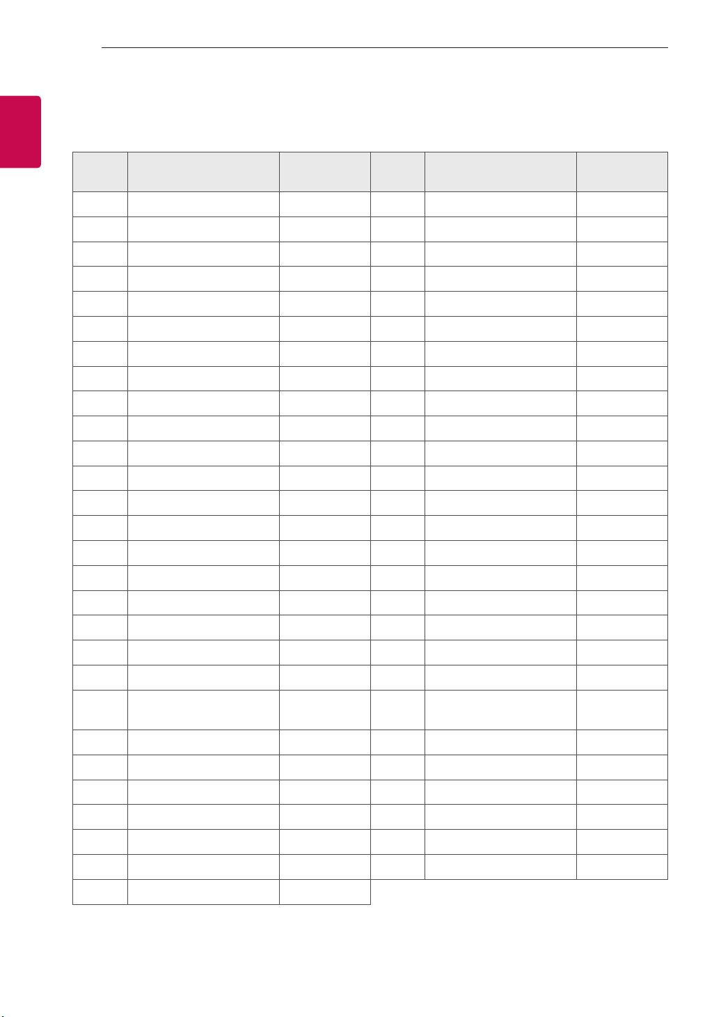
18. Equalizer (Command : j v)
►Adjust EQ of the set.
Transmission [j][v][ ][Set ID][ ][Data][Cr]
0 0 0 0 0 0 0 0
MSB
Frequency Data
LSB
765Frequency 4 3 2 1 0 Step
000 1st Band 0 0 0 0 0 0(decimal)
0012nd Band 0 0 0 0 1 1(decimal)
010 3rd Band ... ... ... ... ... ...
011 4th Band 1 0 0 1 1 19(decimal)
100 5th Band 1 0 1 0 1 20(decimal)
Acknowledgement [v][ ][Set ID][ ][OK/NG][Data][x]
* It depends on model, and can adjust when sound
mode is EQ adjustable value.
19. Energy Saving (Command: j q)
►To reduce the power consumption of the TV. You
can also adjust Energy Saving in PICTURE menu.
Transmission [j][q][ ][Set ID][ ][Data][Cr]
Data
00 : Off
01 : Minimum
02 : Medium
03 : Maximum
04 : Auto (For LCD TV / LED TV) /
Intelligent sensor (For PDP TV)
05 : Screen off
* (Depending on model)
Ack [q][ ][Set ID][ ][OK/NG][Data][x]
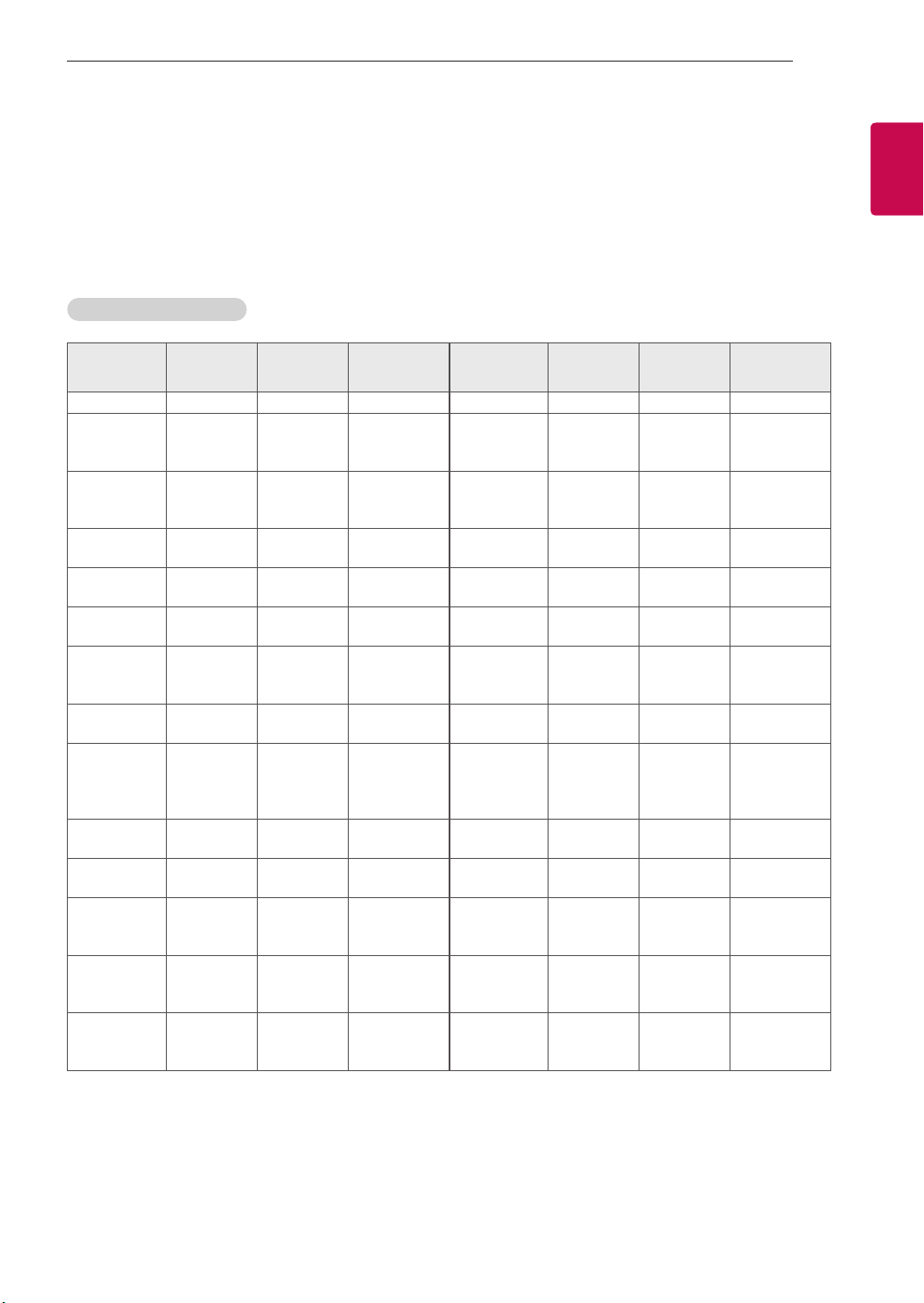
20. Tune Command (Command: m a)
* This command may work differently depending on
model and signal.
• For Europe, Mid-East, Colombia, Asia except
South Korea and Japan Model
►Select channel to following physical number.
Transmission [m][a][ ][Set ID][ ][Data 00][ ]
[Data 01][ ][Data 02][Cr]
* Analog Antenna/Cable
[Data 00][Data 01] Channel Data
Data 00 : High byte channel data
Data 01 : Low byte channel data
- 00 00 ~ 00 C7 (Decimal : 0 ~ 199)
Data 02 : Input Source (Analog)
- 00 : Antenna TV (ATV)
- 80 : Cable TV (CATV)
* Digital Antenna/Cable/Satellite
[Data 00][Data 01]: Channel Data
Data 00 : High Channel data
Data 01 : Low Channel data
- 00 00 ~ 27 0F (Decimal: 0 ~ 9999)
Data 02 : Input Source (Digital)
- 10 : Antenna TV (DTV)
- 20 : Antenna Radio (Radio)
- 40 : Satellite TV (SDTV)
- 50 : Satellite Radio (S-Radio)
- 90 : Cable TV (CADTV)
- a0 : Cable Radio (CA-Radio)
* Tune Command Examples:
1. Tune to the Analog antenna (PAL) Channel 10.
Set ID = All = 00
Data 00 & 01 = Channel Data is 10 = 00 0a
Data 02 = Analog Antenna TV = 00
Result = ma 00 00 0a 00
2. Tune to the digital antenna (DVB-T) Channel 01.
Set ID = All = 00
Data 00 & 01 = Channel Data is 1 = 00 01
Data 02 = Digital Antenna TV = 10
Result = ma 00 00 01 10
3. Tune to the satellite (DVB-S) Channel 1000.
Set ID = All = 00
Data 00 & 01 = Channel Data is 1000 = 03 E8
Data 02 = Digital Satellite TV = 40
Result = ma 00 03 E8 40
Ack [a][ ][Set ID][ ][OK][Data 00][Data 01]
[Data 02][x][a][ ][Set ID][ ][NG][Data 00][x]
• For South Korea, North/Latin America except
Colombia Model
►To tune channel to following physical/major/minor
number.
Transmission [m][a][ ][0][ ][Data00][ ][Data01]
[ ][Data02][ ][Data03][ ][Data04][ ][Data05][Cr]
Digital channels have a Physical, Major, and Minor
channel number. The Physical number is the actual
digital channel number, the Major is the number that
the channel should be mapped to, and the Minor is
the sub-channel. Since the ATSC tuner automatically
maps the channel from the Major / Minor number,
the Physical number is not required when sending a
command in Digital.

10
ENG
ENGLISH
10 EXTERNAL CONTROL DEVICE SETUP
* Analog Antenna/Cable
Data 00 : Physical Channel Number
- Antenna (ATV) : 02~45 (Decimal: 2 ~ 69)
- Cable (CATV) : 01, 0E~7D (Decimal : 1, 14~125)
[Data 01 ~ 04]: Major/Minor Channel Number
Data 01 & 02: xx (Don't care)
Data 03 & 04: xx (Don't care)
Data 05: Input Source (Analog)
- 00 : Antenna TV (ATV)
- 01 : Cable TV (CATV)
* Digital Antenna/Cable
Data 00 : xx (Don't care)
[Data 01][Data 02]: Major Channel Number
Data 01 : High byte Channel Data
Data 02 : Low byte Channel Data
- 00 01 ~ 27 0F (Decimal: 1 ~ 9999)
[Data 03][Data 04]: Minor Channel Number
Data 03 : High byte Channel Data
Data 04 : Low byte Channel Data
Data 05 : Input Source (Digital)
- 02 : Antenna TV (DTV) – Use Physical Channel
Number
- 06 : Cable TV (CADTV) – Use Physical Channel
Number
- 22 : Antenna TV (DTV) – Don’t Use Physical
Channel Number
- 26 : Cable TV (CADTV) - Don’t Use Physical
Channel Number
- 46 : Cable TV (CADTV) – Use Physical/Major
Channel Number Only (One Part Channel)
- 66 : Cable TV (CADTV) – Use Major Channel
Number Only (One Part Channel)
- 0b : Cable DTV Plus – Use Physical Channel
Number
- 2b : Cable DTV Plus – Don’t Use Physical
Channel Number
- 4b : Cable DTV Plus – Use Physical/Major
Channel Number Only (One Part Channel)
- 6b : Cable DTV Plus – Use Major Channel
Number Only (One Part Channel)
Two bytes are available for each major and minor
channel data, but usually the low byte is used alone
(high byte is 0).
* Tune Command Examples:
1. Tune to the Analog cable (NTSC) channel 35.
Set ID = All = 00
Data 00 = Channel Data is 35 = 23
Data 01 & 02 = No Major = 00 00
Data 03 & 04 = No Minor = 00 00
Data 05 = Analog Cable TV = 01
Total = ma 00 23 00 00 00 00 01
2. Tune to the digital antenna (ATSC) channel 30-3.
Set ID = All = 00
Data 00 = Don’t know Physical = 00
Data 01 & 02 = Major is 30 = 00 1E
Data 03 & 04 = Minor is 3 = 00 03
Data 05 = Digital Antenna TV = 22
Total = ma 00 00 00 1E 00 03 22
Ack [a][ ][Set ID][ ][OK][Data 00][Data 01]
[Data 02][Data 03][Data 04][Data 05]
[x][a][ ][Set ID][ ][NG][Data 00][x]
• For Japan Model
►To tune channel to following physical/major/minor
number.
Transmission [m][a][ ][0][ ][Data00][ ][Data01]
[ ][Data02][ ][Data03][ ][Data04][ ][Data05][Cr]
* Digital Antenna/Satellite
Data 00: xx (Don't care)
[Data 01][Data 02]: Major Channel Number
Data 01: High byte Channel Data
Data 02: Low byte Channel Data
- 00 01 ~ 27 0F (Decimal: 1 ~ 9999)
[Data 03][Data 04]: Minor/Branch Channel Number
(Don’t care in Satellite)
Data 03: High byte Channel Data
Data 04: Low byte Channel Data
Data 05 : Input Source (Digital/Satellite for Japan)
- 02 : Antenna TV (DTV)
- 42 : Antenna TV (DTV) – Use Physical/Major
Channel Number Only (One Part Channel)
- 62 : Antenna TV (DTV) – Use Major Channel
Number Only (One Part Channel)
- 07 : BS (Broadcasting Satellite)
- 08 : CS1 (Communication Satellite 1)
- 09 : CS2 (Communication Satellite 2)
* Tune Command Examples:
1
Tune to the digital antenna (ISDB-T) channel 17-1
.
Set ID = All = 00
Data 00 = Don’t know Physical = 00
Data 01 & 02 = Major is 17 = 00 11
Data 03 & 04 = Minor/Branch is 1 = 00 01
Data 05 = Digital Antenna TV = 02
Total = ma 00 00 00 11 00 01 02

11
ENGENGLISH
11
EXTERNAL CONTROL DEVICE SETUP
2. Tune to the BS (ISDB-BS) channel 30.
Set ID = All = 00
Data 00 = Don’t know Physical = 00
Data 01 & 02 = Major is 30 = 00 1E
Data 03 & 04 = Don’t Care = 00 00
Data 05 = Digital BS TV = 07
Total = ma 00 00 00 1E 00 00 07
* This feature is varied based on the model.
Ack [a][ ][Set ID][ ][OK][Data 00][Data 01]
[Data 02][Data 03][Data 04][Data 05]
[x][a][ ][Set ID][ ][NG][Data 00][x]
21. Channel(Programme) Add/Del(Skip)
(Command: m b)
►To skip current channel(programme) for next time.
Transmission [m][b][ ][Set ID][ ][Data][Cr]
Data 00 : Del(ATSC,ISDB)/Skip(DVB) 01 : Add
Ack [b][ ][Set ID][ ][OK/NG][Data][x]
* Set the saved channel status to del(ATSC, ISDB)/
skip(DVB) or add.
22. Key (Command: m c)
►To send IR remote key code.
Transmission [m][c][ ][Set ID][ ][Data][Cr]
Data Key code - p.2.
Ack [c][ ][Set ID][ ][OK/NG][Data][x]
23. Control Backlight (Command: m g)
• For LCD TV / LED TV
►To control the backlight.
Transmission [m][g][ ][Set ID][ ][Data][Cr]
Data Min : 00 to Max : 64
Ack [g][ ][Set ID][ ][OK/NG][Data][x]
Control Panel Light (Command: m g)
• For Plasma TV
►To control the panel light.
Transmission [m][g][ ][Set ID][ ][Data][Cr]
Data Min : 00 to Max : 64
Ack [g][ ][Set ID][ ][OK/NG][Data][x]
24. Input select (Command: x b)
(Main Picture Input)
►To select input source for main picture.
Transmission [x][b][ ][Set ID][ ][Data][Cr]
Data
00 : DTV
02 : Satellite DTV
ISDB-BS (Japan)
03 : ISDB-CS1 (Japan)
04 : ISDB-CS2 (Japan)
11 : CATV
01 : CADTV
10 : ATV
20 : AV or AV1 21 : AV2
40 : Component1
60 : RGB
41 : Component2
90 : HDMI1
92 : HDMI3
91 : HDMI2
93 : HDMI4
Ack [b][ ][Set ID][ ][OK/NG][Data][x]
* This function depends on model and signal.
25. 3D(Command: x t) (only 3D models)
(Depending on model)
►To change 3D mode for TV.
Transmission [x][t][ ][Set ID][ ][Data 00][ ][Data 01]
[ ][Data 02][ ][Data 03][Cr]
* (Depending on model)
Data Structure
[Data 00] 00 : 3D On
01 : 3D Off
02 : 3D to 2D
03 : 2D to 3D
[Data 01] 00 : Top and Bottom
01 : Side by Side
02 : Check Board
03 : Frame Sequential
04 : Column interleaving
05 : Row interleaving
[Data 02] 00 : Right to Left
01 : Left to Right
[Data 03] 3D Effect(3D Depth): Min : 00 - Max : 14
(*transmit by Hexadecimal code)

12
ENG
ENGLISH
12 EXTERNAL CONTROL DEVICE SETUP
* [Data 02], [Data 03] functions depend on model
and signal.
* If [Data 00] is 00 (3D On), [Data 03] has no
meaning.
* If [Data 00] is 01 (3D off) or 02 (3D to 2D), [Data
01], [Data 02] and [Data 03] have no meaning.
* If [Data 00] is 03 (2D to 3D), [Data 01] and
[Data 02] have no meaning.
* If [Data 00] is 00 (3D On) or 03 (2D to 3D), [Data
03] works when 3D Mode (Genre) is manual only.
* All 3D pattern options ([Data 01]) may not be
available according to broadcasting/video signal.
[Data 00] [Data 01] [Data 02] [Data 03]
00 O O O
01 X X X
02 X X X
03 X O O
X : don’t care
Ack [t][ ][Set ID][ ][OK][Data00][Data01][Data02]
[Data03][x]
[t][ ][Set ID][ ][NG][Data00][x]
26. Extended 3D(Command: x v) (only 3D models)
(Depending on model)
►To change 3D option for TV.
Transmission [x][v][ ][Set ID][ ][Data 00][ ]
[Data 01][Cr]
[Data 00] 3D option
00 : 3D Picture Correction
01 : 3D Depth (3D Mode is Manual Only)
02 : 3D Viewpoint
06 : 3D Color Correction
07 : 3D Sound Zooming
08 : Normal Image View
09 : 3D Mode (Genre)
[Data 01] It has own range for each 3D option
determined by [Data 00].
1) When [Data 00] is 00
00 : Right to Left
01 : Left to Right
2) When [Data 00] is 01, 02
Data Min: 0 - Max: 14 (*transmit by Hexadecimal
code)
Data value range(0 - 20) converts Viewpoint range
(-10 - +10) automatically (Depending on model)
* This option works when 3D Mode (Genre) is manual
only.
3) When [Data 00] is 06, 07
00 : Off
01 : On
4) When [Data 00] is 08
00 : Revert to 3D video from 3D-to-2D
converted 2D video
01 : Change 3D video to 2D video, except
2D-to-3D video
* If conversion condition doesn’t meet, command is
treated as NG.
5) When [Data 00] is 09
00 : Standard
02 : Cinema
04 : Manual
01 : Sport
03 : Extreme
05 : Auto
Ack [v][ ][Set ID][ ][OK][Data00][Data01][x]
[v][ ][Set ID][ ][NG][Data00][x]
27. Auto Configure (Command: j u)
(Depending on model)
►To adjust picture position and minimize image
shaking automatically. It works only in RGB (PC)
mode.
Transmission [j][u][ ][Set ID][ ][Data][Cr]
Data 01 : To set Auto Configure
Ack [u][ ][Set ID][ ][OK/NG][Data][x]


2
Important Safety Instruction
•Read these instructions.
•Keep these instructions.
•Heed all warnings.
•Follow all instructions.
•Do not use this apparatus near water.
•Clean only with dry cloth.
•Do not block any ventilation openings. Install in accordance with the manufacturer’s instructions.
•Do not install near any heat sources such as radiators, heat registers, stoves, or other apparatus (including amplifiers) that produce heat.
•Do not defeat the safety purpose of the polarized or grounding-type plug. A polarized plug has two blades with one wider than the other. A grounding type
plug has two blades and a third grounding prong.The wide blade or the third prong are provided for your safety. If the provided plug does not fit into your
outlet, consult an electrician for replacement of the obsolete outlet.
•Protect the power cord from being walked on or pinched particularly at plugs, convenience receptacles, and the point where they exit from the apparatus.
•Only use attachments/accessories specified by the manufacturer.
•Use only with the cart, stand, tripod, bracket, or table specified by the manufacturer, or sold with the apparatus.When a cart is used, use caution when
moving the cart/apparatus combination to avoid injury from tip-over.
•Unplug this apparatus during lightning storms or when unused for long periods of time.
•Refer all servicing to qualified service personnel. Servicing is required when the apparatus has been damaged in any way, such as power-supply cord or
plug is damaged, liquid has been spilled or objects have fallen into the apparatus, the apparatus has been exposed to rain or moisture, does not operate
normally, or has been dropped.
Before reading this manual
•Read this manual thoroughly before operating yourTV, and keep it for future reference.
•On the website you can download the manual including installation, using, troubleshooting, specifications, license etc and view its contents on your PC or
mobile device.
•User Guide : For more information about thisTV, read the USER GUIDE embedded in the product. (Depending upon model)
-To open the USER GUIDE → → [Support] →[User Guide]
Optional Extras
•Optional extras can be changed or modified for quality improvement without any notification. Contact your dealer for buying these items.These devices
work only with certain models.
•The model name or design may be changed due to the manufacturer’s circumstances or policies.
•A cable to connect antennas and external devices must be purchased separately.
Note
•Product specifications or contents of this manual may be changed without prior notice due to upgrade of product functions.
•The items supplied with your product may vary depending upon the model.
•Image shown may differ from yourTV.
By using this product, you agree that all disputes between you and LG arising out of or relating in any way to this product (including but not limited to warranty
disputes) shall be resolved exclusively through binding arbitration on an individual basis.The terms of the arbitration agreement (including details on the
procedure for resolving disputes) is available at www.lg.com/us/arbitration (USA) or www.lg.com/ca_en/arbitration (Canada).

3
Warning! Safety instructions
CAUTION
RISK OF ELECTRIC SHOCK
DO NOT OPEN
CAUTION:TO REDUCETHE RISK OF ELECTRIC SHOCK DO NOT REMOVE COVER (OR BACK). NO USER SERVICEABLE PARTS INSIDE. REFERTO QUALIFIED SERVICE
PERSONNEL.
The symbol is intended to alert the user to the presence of uninsulated dangerous voltage within the product’s enclosure that may be of sufficient
magnitude to constitute a risk of electric shock to persons.
The symbol is intended to alert the user to the presence of important operating and maintenance (servicing) instructions in the literature
accompanying the device.
WARNING:TO REDUCETHE RISK OF FIRE AND ELECTRIC SHOCK, DO NOT EXPOSETHIS PRODUCT TO RAIN OR MOISTURE.
•TO PREVENTTHE SPREAD OF FIRE, KEEP CANDLES OR OTHER ITEMSWITH
OPEN FLAMES AWAY FROM THIS PRODUCT AT ALL TIMES.
•Do not place the TV and/or remote control in the following
environments:
-Keep the product away from direct sunlight.
-An area with high humidity such as a bathroom.
-Near any heat source such as stoves and other devices that produce
heat.
-Near kitchen counters or humidifiers where they can easily be exposed
to steam or oil.
-An area exposed to rain or wind.
-Do not expose to dripping or splashing and do not place objects filled
with liquids, such as vases, cups, etc. on or over the apparatus (e.g., on
shelves above the unit).
-Near flammable objects such as gasoline or candles, or expose theTV
to direct air conditioning.
-Do not install in excessively dusty places.
Otherwise, this may result in fire, electric shock, combustion/explosion,
malfunction or product deformation.
•Ventilation
-Install yourTV where there is proper ventilation. Do not install in a
confined space such as a bookcase.
-Do not install the product on a carpet or cushion.
-Do not block or cover the product with cloth or other materials while
unit is plugged in.
•Take care not to touch the ventilation openings.When watching theTV
for a long period, the ventilation openings may become hot.
•Protect the power cord from physical or mechanical abuse, such as being
twisted, kinked, pinched, closed in a door, or walked upon. Pay particular
attention to plugs, wall outlets, and the point where the cord exits the
device.
•Do not move theTV whilst the Power cord is plugged in.
•Do not use a damaged or loosely fitting power cord.
•Be sure to grasp the plug when unplugging the power cord. Do not pull
on the power cord to unplug theTV.
•Do not connect too many devices to the same AC power outlet as this
could result in fire or electric shock.
•Disconnecting the Device from the Main Power
-The power plug is the disconnecting device. In case of an emergency,
the power plug must remain readily accessible.
•Do not let your children climb or cling onto theTV. Otherwise, theTV
may fall over, which may cause serious injury.
•Outdoor Antenna Grounding (Can differ by country):
-If an outdoor antenna is installed, follow the precautions below.
An outdoor antenna system should not be located in the vicinity of
overhead power lines or other electric light or power circuits, or where
it can come in contact with such power lines or circuits as death or
serious injury can occur.
Be sure the antenna system is grounded to provide some protection
against voltage surges and built-up static charges.
Section 810 of the National Electrical Code (NEC) in the U.S.A. provides
information with respect to proper grounding of the mast and
supporting structure, grounding of the lead-in wire to an antenna
discharge unit, size of grounding conductors, location of antenna
discharge unit, connection to grounding electrodes and requirements
for the grounding electrode.
Antenna grounding according to the National Electrical Code, ANSI/
NFPA 70
•Never touch this apparatus or antenna during a lightning storm.You may
be electrocuted.
•Make sure the power cord is connected securely to theTV and wall socket
if not secured damage to the Plug and socket may occur and in extreme
cases a fire may break out.
•Do not insert metallic or inflammable objects into the product. If a
foreign object is dropped into the product, unplug the power cord and
contact the customer service.
•Do not touch the end of the power cord while it is plugged in.You may
be electrocuted.

4
•If any of the following occur, unplug the product immediately
and contact your local customer service.
-The product has been damaged.
-If water or another substance enters the product (like an AC adapter,
power cord, orTV).
-If you smell smoke or other odors coming from theTV
-When lightning storms or when unused for long periods of time.
Even theTV is turned off by remote control or button, AC power source is
connected to the unit if not unplugged in.
•Do not use high voltage electrical equipment near the TV (e.g., a bug
zapper).This may result in product malfunction.
•Do not attempt to modify this product in any way without written
authorization from LG Electronics. Accidental fire or electric shock
can occur. Contact your local customer service for service or repair.
Unauthorized modification could void the user’s authority to operate
this product.
•Use only an authorized attachments / accessories approved by LG
Electronics. Otherwise, this may result in fire, electric shock, malfunction,
or product damage.
•Never disassemble the AC adapter or power cord.This may result in fire
or electric shock.
•Handle the adapter carefully to avoid dropping or striking it. An impact
could damage the adapter.
•To reduce the risk of fire or electrical shock, do not touch the TV with wet
hands. If the power cord prongs are wet or covered with dust, dry the
power plug completely or wipe dust off.
•Batteries
-Store the accessories (battery, etc.) in a safe location out of the reach
of children.
-Do not short circuit, disassemble, or allow the batteries to overheat.
Do not dispose of batteries in a fire. Batteries should not be exposed
to excessive heat.
-Caution: Risk of fire or explosion if the battery is replaced by an
incorrect type.
•Moving
-When moving, make sure the product is turned off, unplugged, and
all cables have been removed. It may take 2 or more people to carry
largerTVs. Do not press or put stress on the front panel of theTV.
Otherwise, this may result in product damage, fire hazard or injury.
•Keep the packing anti-moisture material or vinyl packing out of the
reach of children.
•Do not allow an impact shock, any objects to fall into the product, and do
not drop anything onto the screen.
•Do not press strongly upon the panel with a hand or a sharp object such
as a nail, pencil, or pen, or make a scratch on it. It may causedamage
to screen.
•Cleaning
-When cleaning, unplug the power cord and wipe gently with a soft/
dry cloth. Do not spray water or other liquids directly on theTV. Do
not clean yourTV with chemicals including glass cleaner, any type of
air freshener, insecticide, lubricants, wax (car, industrial), abrasive,
thinner, benzene, alcohol etc., which can damage the product and/
or its panel. Otherwise, this may result in electric shock or product
damage.
Installation
Lifting and moving the TV
When moving or lifting theTV, read the following to prevent theTV from
being scratched or damaged and for safe transportation regardless of its type
and size.
•It is recommended to move theTV in the box or packing material that
theTV originally came in.
•Before moving or lifting theTV, disconnect the power cord and all cables.
•When holding theTV, the screen should face away from you to avoid
damage.
•Hold the top and bottom of theTV frame firmly. Make sure not to hold
the transparent part, speaker, or speaker grille area.
•Use at least two people to move a largeTV.
•When transporting the TV, do not expose the TV to jolts or excessive
vibration.
•When transporting the TV, keep the TV upright; never turn theTV on its
side or tilt towards the left or right.
•When handling theTV, be careful not to damage the protruding buttons.
•Avoid touching the screen at all times, as this may result in damage to
the screen.
•Do not place the product on the floor with its front facing down without
padding. Failure to do so may result in damage to the screen.
•When attaching the stand to theTV set, place the screen facing down on
a cushioned table or flat surface to protect the screen from scratches.
Mounting on the Table
1 Lift and tilt theTV into its upright position on a table.
• Leave a minimum of 10 cm (4 inches) space from the wall for proper
ventilation.
2 Connect the power cord to a wall outlet.

5
•Do not apply foreign substances (oils, lubricants, etc.) to the screw parts
when assembling the product. (Doing so may damage the product.)
•If you install theTV on a stand, you need to take actions to prevent the
product from overturning. Otherwise, the product may fall over, which
may cause injury.
•Do not use any unapproved items to ensure the safety and lifespan of
the product.
•Any damages or injuries by using unapproved items are not covered by
the warranty.
•Make sure that the screws are fastened tightly. (If they are not fastened
securely enough, theTV may tilt forward after being installed.)
•Do not fasten the screws with excessive force otherwise they may strip
and become loose.
Securing TV to the Wall
1 Insert and tighten the eye-bolts or TV brackets and bolts on the back of
theTV.
• If there are bolts inserted at the eye-bolts position, remove the bolts
first.
2 Mount the wall brackets with the bolts to the wall. Match the location of
the wall bracket and the eye-bolts on the rear of theTV.
3 Connect the eye-bolts and wall brackets tightly with a sturdy rope or
cable. Make sure to keep the rope parallel to the flat surface.
•Use a platform or cabinet that is strong and large enough to support the
TV securely.
•Brackets, bolts, and ropes are optional.You can obtain additional
accessories from your local dealer.
Mounting to the Wall
An optional wall mount can be used with your LG Television. Consult with
your local dealer for a wall mount that supports the VESA standard used by
yourTV model. Carefully attach the wall mount bracket at the rear of theTV.
Install the wall mount bracket on a solid wall perpendicular to the floor. If
you are attaching theTV to other building materials, please contact qualified
personnel to install the wall mount. Detailed instructions will be included
with the wall mount.We recommend that you use an LG brand wall mount.
The LG wall mount is easy to adjust or to connect the cables.When you do
not use LG’s wall mount bracket, use a wall mount bracket where the device
is adequately secured to the wall with enough space to allow connectivity to
external devices. If you are using a non-adjustable mount, attach the mount
to the wall. Attach the cables to theTV first, then attach theTV to the mount.
•Remove the stand before installing theTV on a wall mount by
performing the stand attachment in reverse.
•For more information of screws and wall mount bracket, refer to the
Separate Purchase.
•If you intend to mount the product to a wall, attachVESA standard
mounting interface (optional parts) to the back of the product.When you
install the set to use the wall mounting bracket (optional parts), fix it
carefully so as not to drop.
•When mounting aTV on the wall, make sure not to install theTV by
hanging the power and signal cables on the back of theTV.
•Do not install this product on a wall if it could be exposed to oil or oil
mist.This may damage the product and cause it to fall.
•Please use the accessory cable holder when hanging on the wall. (Only
OLED48/83C2*)
Antenna/Cable
Connect an antenna, cable, or cable box to watchTV while referring to the
following.The illustrations may differ from the actual items and an RF cable
is optional.
Copper wire
•Make sure not to bend the copper wire of the RF cable.
•Complete all connections between devices, and then connect the power
cord to the power outlet to prevent damage to yourTV.
•Use a signal splitter to use 2TVs or more.
•DTV Audio Supported Codec: MPEG, Dolby Digital
•ThisTV cannot receive Ultra HD (3840x2160pixels) broadcasts directly
because the related standards have not been confirmed (Depending
upon country).
•Use the AV cover for aesthetic purposes. Connecting too many cables may
cause lifting problems. In such a case, remove the AV cover before use.

6
Starting TV
Turning on the TV
You can simply operate theTV functions, using the button.
<A type>
Power On (Press)
Power Off1) (Press and Hold)
Menu Control (Press2))
Menu Selection (Press and Hold3))
1) All running apps will close.
2) You can access and adjust the menu by pressing the button whenTV is on.
3) You can use the function when you access menu control.
<B type>
Power On (Press)
Power Off1) (Press and hold)
Volume Control
Channels Control
1) All running apps will close.
Note
•When theTV is turned on for the first time after being shipped from the
factory, initialization of theTV may take approximately one minute..

7
Connections
You can connect various external devices to theTV. For more information on
external device’s connection, refer to the manual provided with each device.
HDMI
•When connecting the HDMI cable, the product and external devices
should be turned off and unplugged.
•Supported HDMI Audio format (Depending upon model):
True HD (48 kHz),
Dolby Digital / Dolby Digital Plus (32 kHz / 44.1 kHz / 48 kHz),
PCM (32 kHz / 44.1 kHz / 48 kHz / 96 kHz / 192 kHz)
Note
•If the device connected to Input Port also supports HDMI Deep Color,
your picture may be clearer. However, if the device doesn’t support it, it
may not work properly. In that case, change theTV’s [HDMI Deep Color]
setting to off.
•→→[General] →[Devices] →[HDMI Settings] → [HDMI
Deep Color]
•Use a certified cable with the HDMI logo attached. If you do not use a
certified HDMI cable, the screen may not display or a connection error
may occur.
•Recommended HDMI cable types (3m (9.84feet) or less)
-Ultra High Speed HDMI®/™ cable
USB
Some USB Hubs may not work. If a USB device connected through a USB Hub
is not detected, connect it directly to the USB port on the TV.
Note
•For an optimal connection, HDMI cables and USB devices should have
bezels less than 10 mm (0.39 inches) thick and 18 mm (0.7 inches)
width.
•Use an extension cable that supports if the USB cable or USB
flash drive does not fit into yourTV’s USB port.
IR Blaster
Control the set-top box (cable/satellite/IP/OTT), Blu-ray/DVD player,
soundbar, game consoles, etc., using the IR Blaster. (Depending upon country)
(Depending upon models)
•Connect the IR Blaster cable to theTV’s IR Blaster port.
•Use universal control settings to control the device.
•Secure the IR Blaster with the 3M tape provided.
External Devices
Supported external devices are: Blu-ray player, HD receivers, DVD players,
VCRs, audio systems, USB storage devices, PC, gaming devices, and other
external devices.
Note
•The external device connections shown may differ slightly from
illustrations in a manual.
•In PC mode, there may be noise associated with the resolution, vertical
pattern, contrast or brightness. If noise is present, change the PC output
to another resolution, change the refresh rate to another rate or adjust
the brightness and contrast on the [Picture] menu until the picture is
clear. Depending upon the graphics card, some resolution settings may
not allow the image to be positioned on the screen properly.
•When connecting to a wired LAN, use a CAT7 cable with high-speed
Internet transmission.
•TheTV may be capable of operating without a set-top-box from a
multichannel video programming distributor (MVPD).
Remote RS-232C setup
To obtain the RS-232C external control setup information, please visit www.
lg.com. Download and read the manual, (Depending upon model).
•Do not drop the product or let it fall over when connecting external
devices. Otherwise, this may result in injury or damage to the product.
•When connecting external devices such as video game consoles, make
sure the connecting cables are long enough. Otherwise, the product may
fall over, which may cause injury or damage the product.
This manual suits for next models
22
Table of contents
Languages:
Other LG OLED TV manuals

LG
LG EA87 series User manual

LG
LG OLED65C7P Parts list manual

LG
LG SIGNATURE OLED77W9PSA User manual

LG
LG OLED55B8 Series Parts list manual

LG
LG OLED55B9PUA User manual

LG
LG OLED55BXPSA User manual

LG
LG 55EG965T-TA User manual

LG
LG OLED55GXPUA User manual

LG
LG OLED55C6V.AEK Parts list manual

LG
LG OLED55B1PTA User manual