- 6 - LGE Internal Use OnlyCopyright©2008 LG Electronics. Inc. All right reserved.
Only for training and service purposes
ADJUSTMENT INSTRUCTION
1. Application Object
These instructions are applied all of the 42” PLASMA TV,
PD81A Chassis.
2. Note
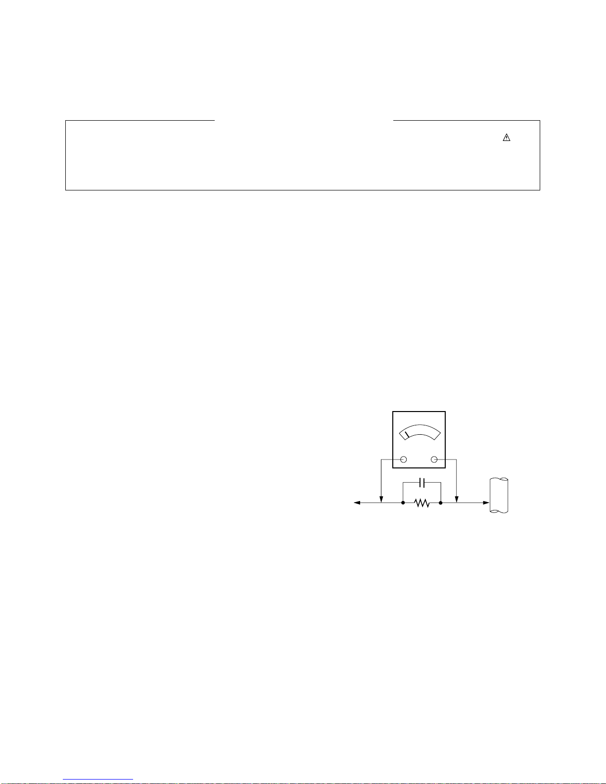
(1) Because this is not a hot chassis, it is not necessary to use
an isolation transformer. However, the use of isolation
transformer will help protect test instrument.
(2) Adjustment must be done in the correct order.
(3) The adjustment must be performed in the circumstance of
25±5°C of temperature and 65±10% of relative humidity if
there is no specific designation.
(4) The input voltage of the receiver must keep 100-240V~,
50/60Hz.
(5) The receiver must be operated for about 15 minutes prior
to the adjustment.
OAfter RGB Full white HEAT-RUN Mode, the receiver must
be operated prior to adjustment.
OEnter into HEAT-RUN MODE
1) Press the POWER ON KEY on R/C for adjustment.
2) OSD display and screen display PATTERN MODE.
- Select “3. Test Pattern” by using D/E(CH+/-) and
press ENTER(V)
- Select “White” by using (F/GVOL+/-) and press
ENTER(V)
* Set is activated HEAT-RUN without signal generator in
this mode.
* Single color pattern(RED/BLUE/GREEN) of HEAT-RUN
mode uses to check PANEL.
3.
S/W auto download using the USB
Memory stick
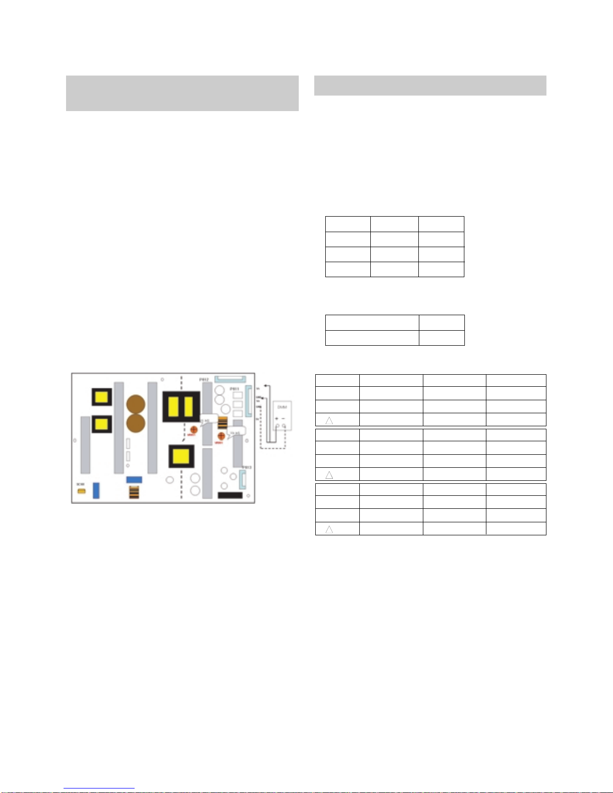
(1) Insert the USB memory sick the PCB ASSEMBLY.
(2) Using ‘power on’ button of the control R/C, power on TV.
(3) S/W download process is executed automatically.
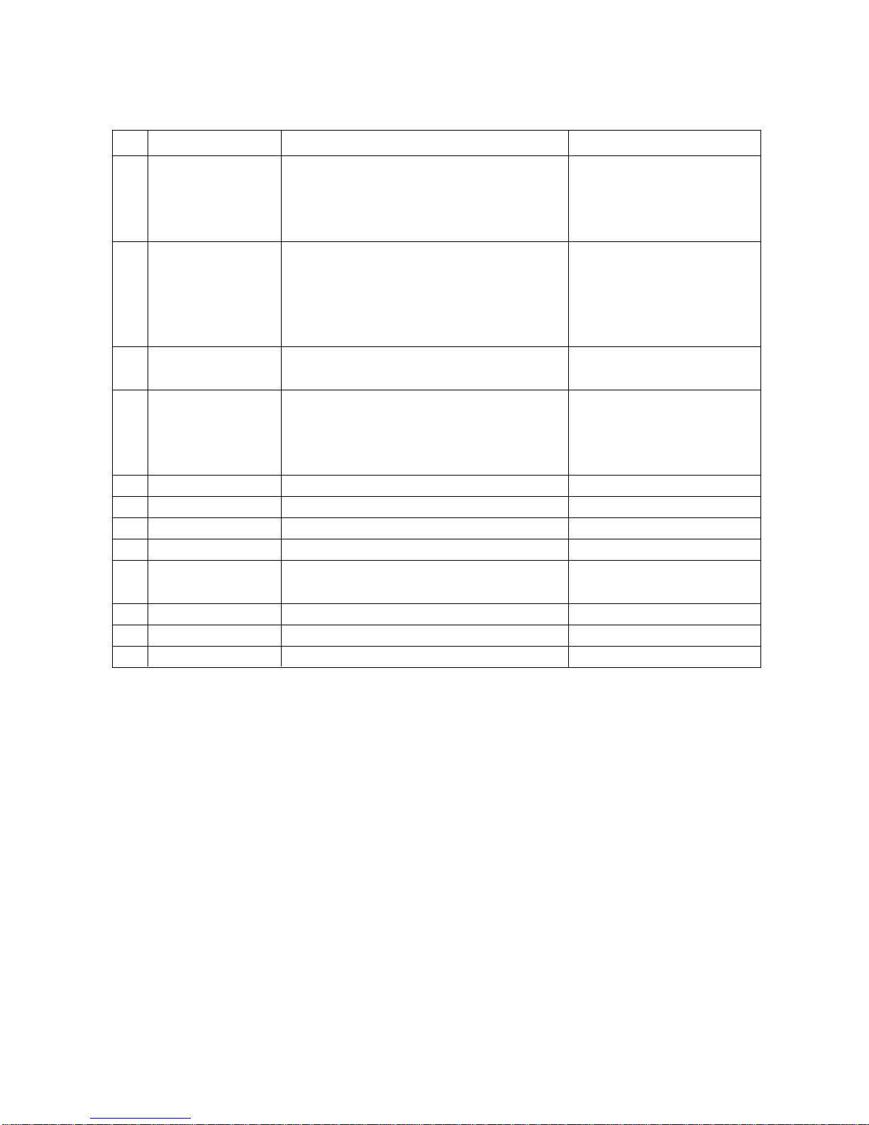
4.
Auto-control adjustment process
V
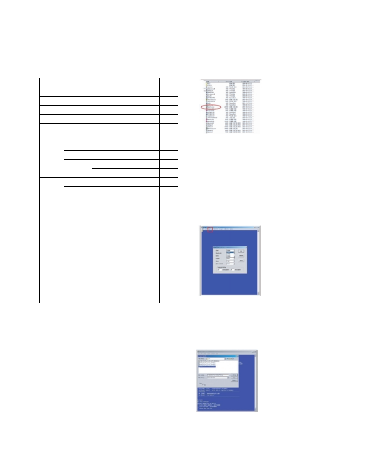
All adjustment process is executed one time through RS-232C.
V Command send -> ADC Calibration -> Model name
download -> EDID download.
VAdjsutment process protocol(RS-232C)
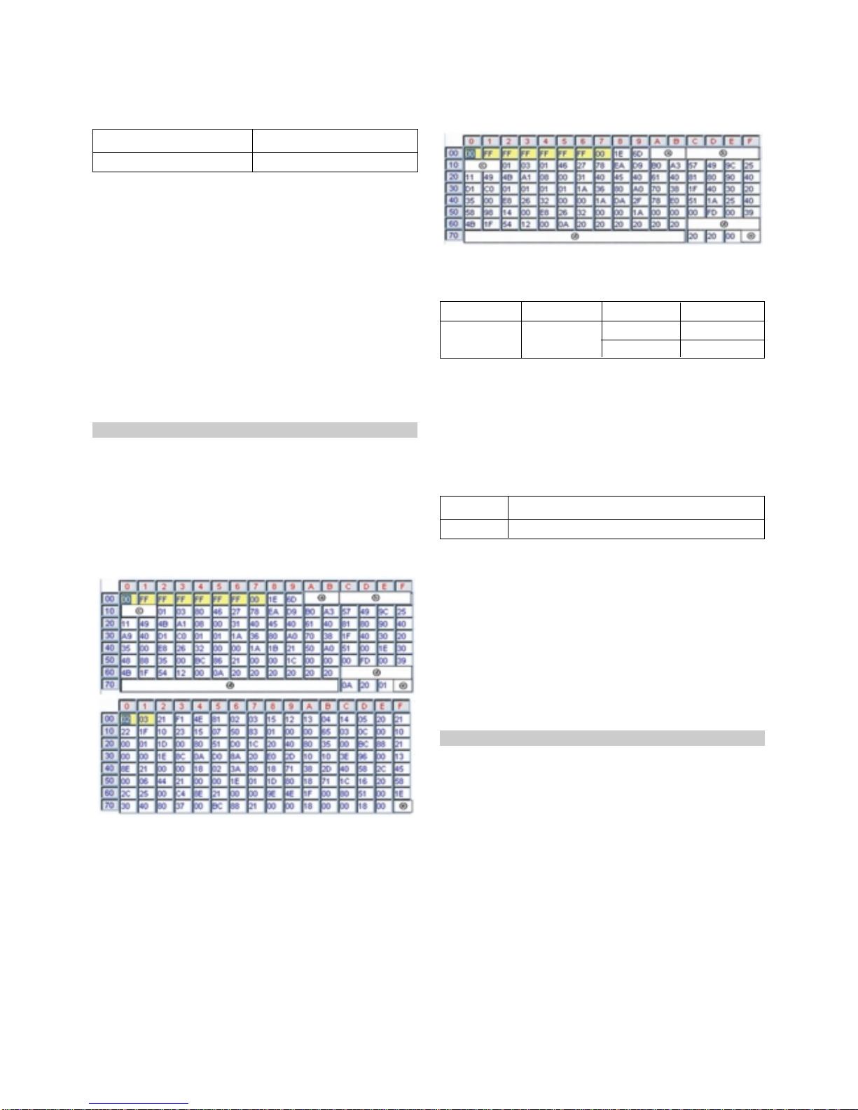
5. Manual model name download
(1) Press ADJ KEY on R/C for model name D/L.
(2) Select “0.Model Option” and press ENTER(V).
(3) Select model name by using D/E(CH+/-)and press
ENTER(V).
* Using ‘power on’ button off the control R/C, power on TV.
All adjustment process is executed one time through RS-232C.
Do not connect extrenal input calbe.
* Using ‘power on’ button of the control R/C, power on TV.
USB file(EPK) version must be bigger than downloaded
version of main B/D.
* Using ‘power on’ button off the control R/C, power on TV.
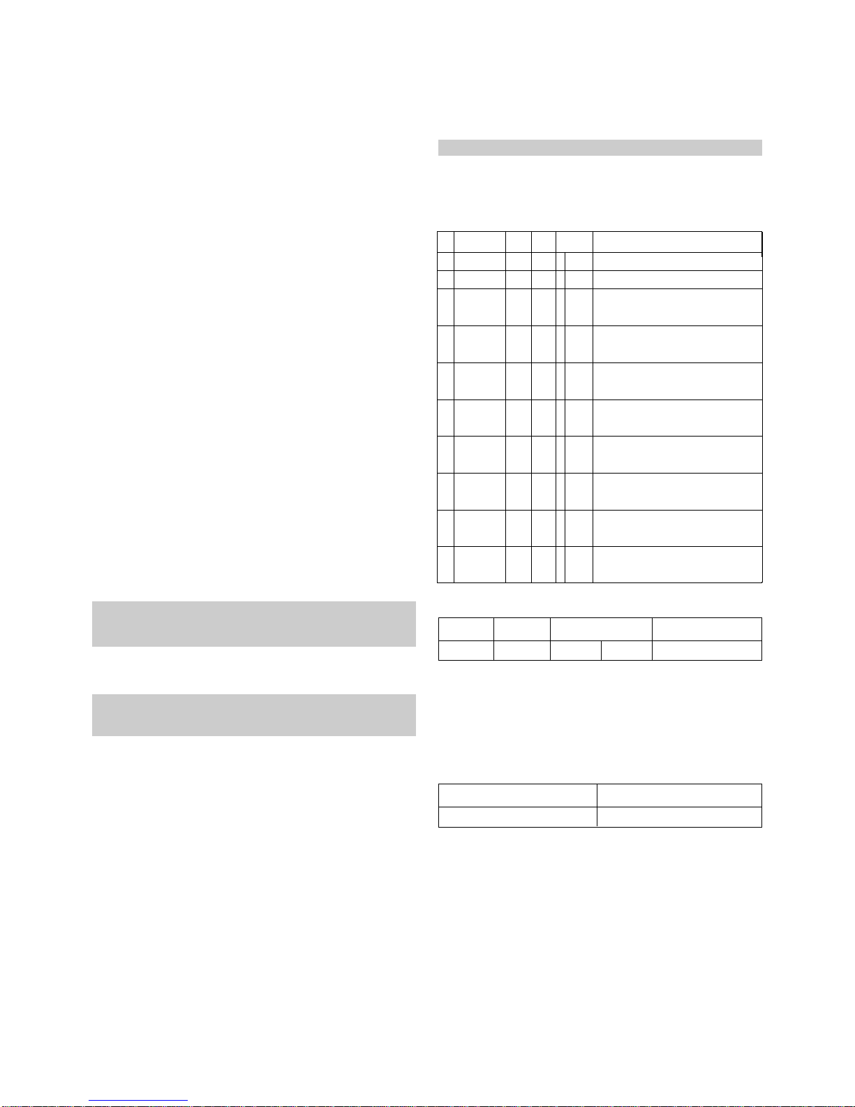
1
2
3
4
5
6
7
8
9
10
Ready
ADC
ADC
Confirmation
ADC
Mode Out
Download
Mode In
EDID
Download
Check EDID
Status
Define model
name
Adjustment
Confirmation
Download
Mode Out
NO
Item Remark
CMD1 CMD2
Data 0
a
a
a
a
a
a
a
a
a
a
d
d
d
d
e
e
e
e
e
e
0
0
9
0
0
0~4,9
0~4,9
1~7
9
0
0
1
9
9
0
1
2
5
9
9
Ready
ADC start
Transmitting adjustment mode In
instruction, operate adjustment command.
All=0 ; HDMI1,2,3,4=1,2,3,4 ; RGB=9
All=0 ; HDMI1,2,3,4=1,2,3,4 ; RGB=9
Model define index(Data0) are listed at
next table.
EDID data existence check in SET
assembly
ae53
42PG6000-ZA
CMD1 CMD2 Data 0 Remark
42PG6000-ZA 56000000
Model Name Model Option Value