4
ENG
ENGLISH
TABLEOFCONTENTS
TABLEOFCONTENTS
2 LICENSES
6 ASSEMBLINGANDPREPARING
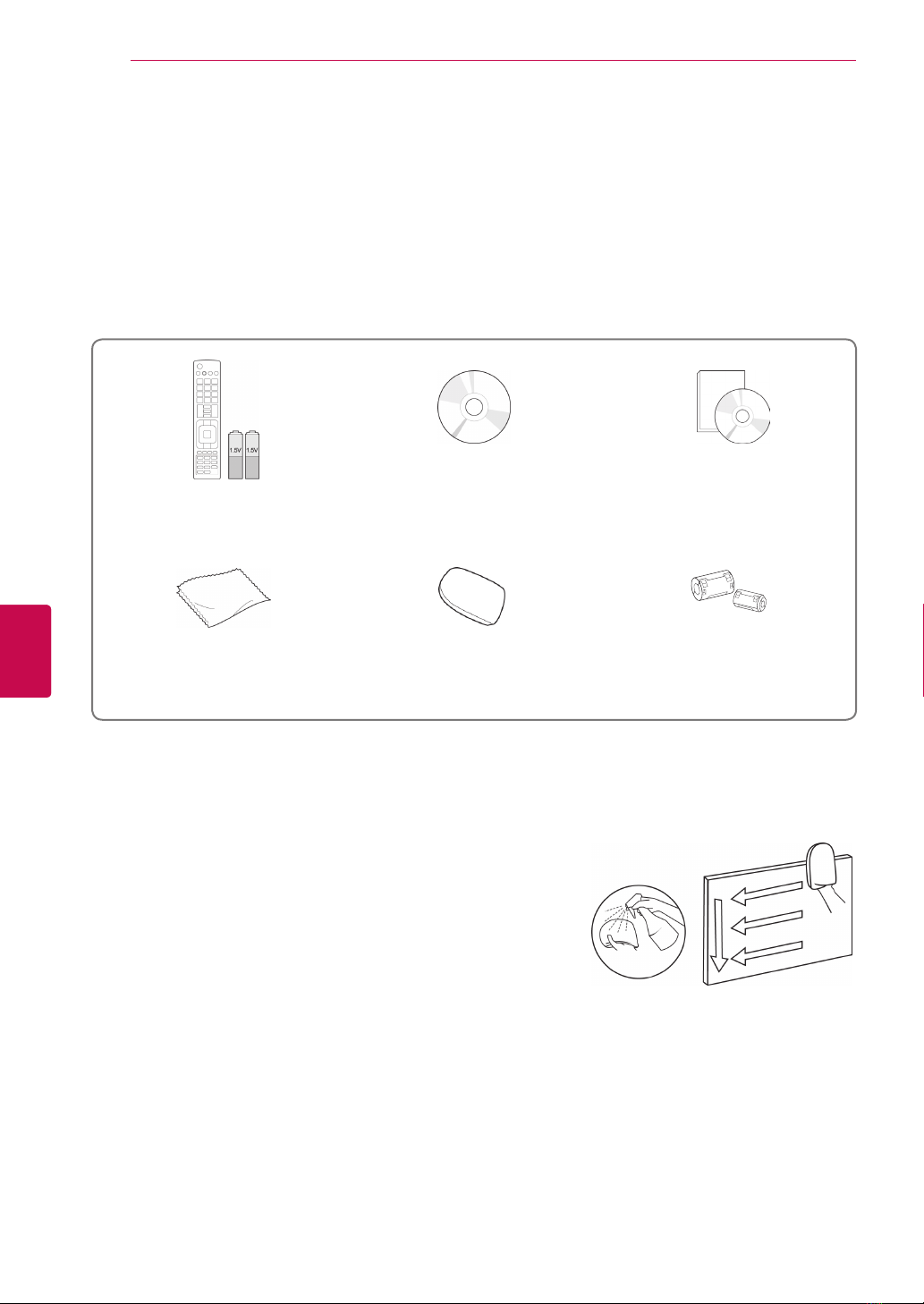
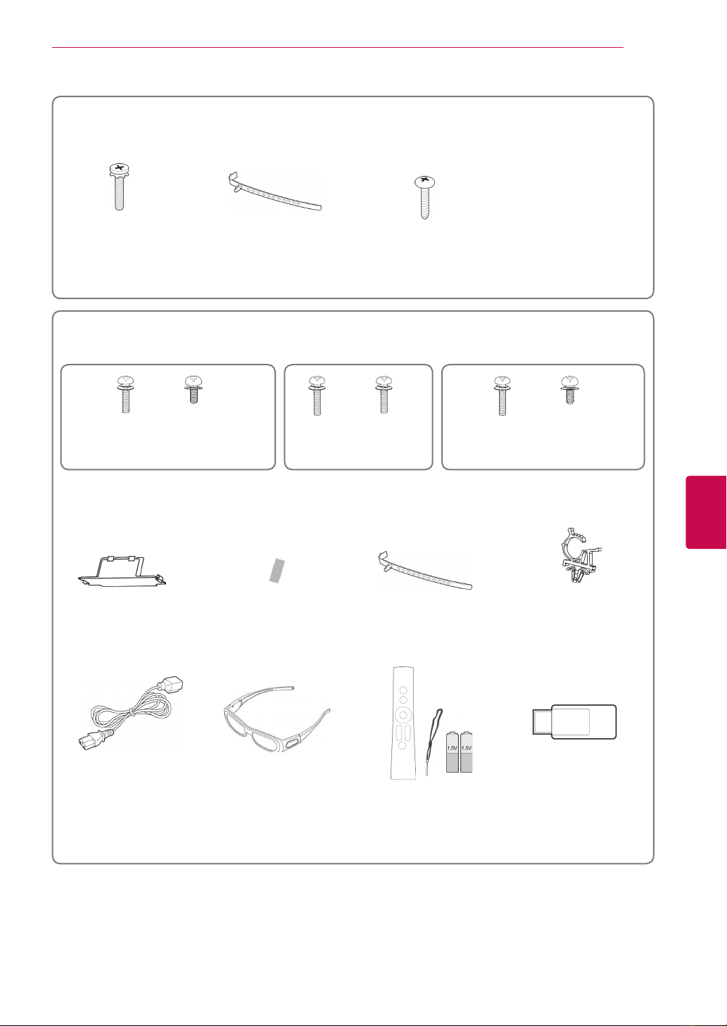
6 Unpacking
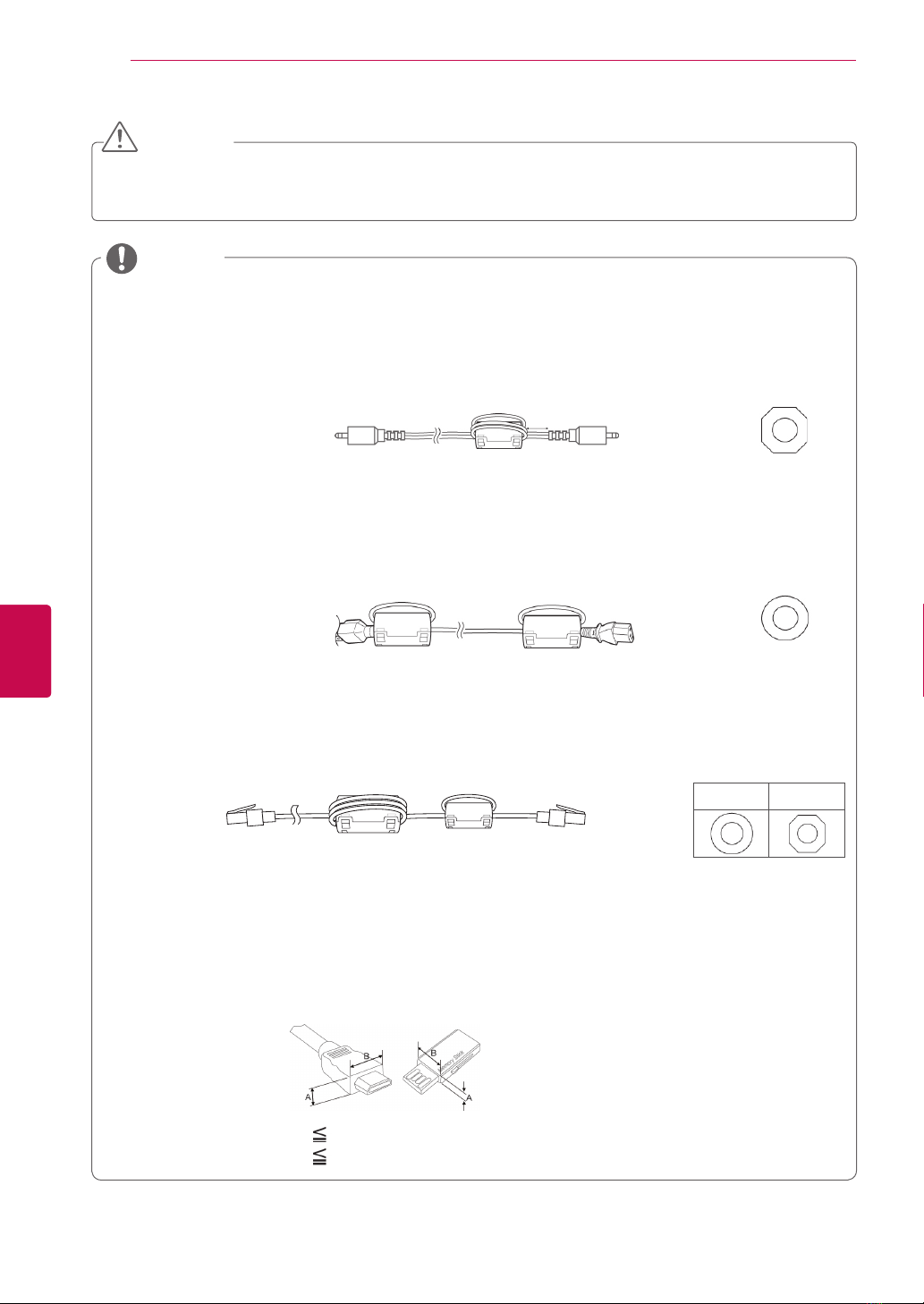
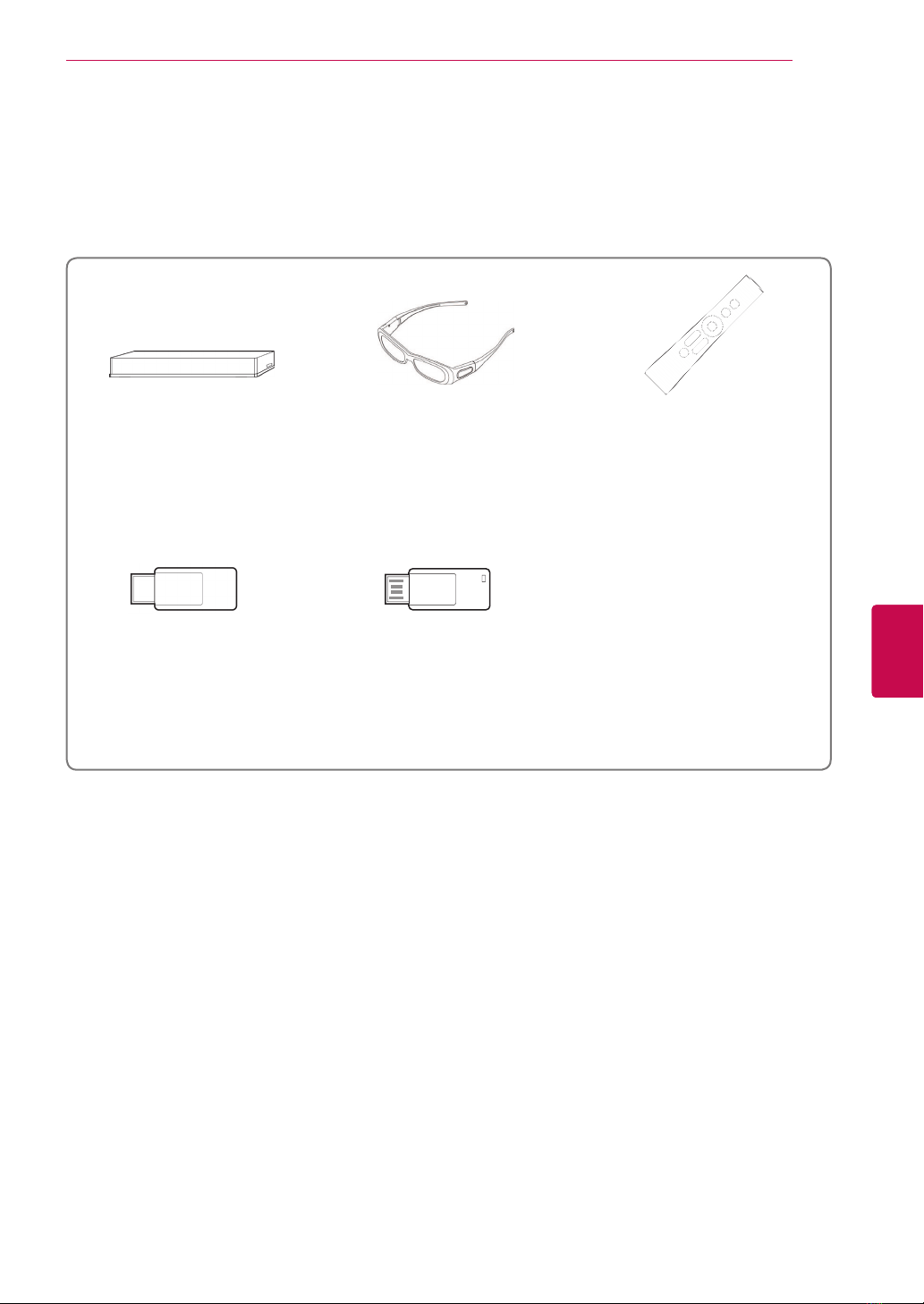
9 Separate purchase
10 Parts and buttons
14 Lifting and moving the TV
14 Setting up the TV
14 - Attaching the stand
17 - Not using the Desk-Type Stand
17 - Mounting on a table
19 - Mounting on a wall
20 - Tidying cables
21 REMOTECONTROL
24 Magic Motion Remote Control Functions
25 - Registering Magic Motion Remote Control
25 - How to use Magic Motion Remote Control
25 - Precautions to Take when Using the
Magic Motion Remote Control
26 WATCHINGTV
26 Connecting to an antenna
26 - Connecting an antenna
26 - Connecting with a satellite dish
27 Turning the TV on for the first time
27 Watching TV
28 Accessing Home menu
29 Managing programmes
29 - Automatically setting up programme
32 - Cable DTV Setting
32 - Satellite DTV Setting
33 - Tivu Programme List Update
34 - Manually setting up programme (In
digital mode)
35 - Manually setting up programme (In
analogue mode)
37 - Editing your programme list
38 - Booster
38 - Using favourite programmes
38 - CI [Common interface] Information
39 Using additional options
39 - Adjusting aspect ratio
40 - Changing AV modes
41 - Using the input list
42 Using the quick menu
43 ENTERTAINMENT
43 Network Connection
43 - Connecting to a wired network
44 - Connecting to a wireless network
46 - When a security code is already set
49 - Network Status
50 Premium Account Function
50 - Notice
52 LG Apps Function
52 - Registration LG Apps
53 - Sign in with your LG Apps account
54 - Using LG Apps
55 - Using My Apps
56 Smart Share Function
56 - Connecting USB storage devices
57 - Connecting DLNA DMP (Digital Living
Network Alliance, Digital Media Player)
60 - Connecting DLNA DMR (Digital Living
Network Alliance, Digital Media Render)
61 - Browsing files
62 - Viewing Videos
65 - DivX registration code
66 - Viewing Photos
68 - Listening to music
70 DVR Function
70 - Precautions when using the USB Device
71 - Timeshift (PAUSE & REPLAY OF LIVE
TV)
74 - RECORDING
75 - SCHEDULE
78 - RECORDED TV
81 EPG (Electronic Programme Guide)
Function (In digital mode)
81 - Switch on/off EPG
81 - Select a programme
82 - NOW/NEXT Guide Mode
82 - 8 Day Guide Mode
82 - Date Change Mode
82 - Extended Description Box
83 3DIMAGING
83 3D Technology
84 When using 3D Glasses
84 3D Imaging Viewing Range
84 Viewing 3D Imaging
85 - Setting 3D Imaging