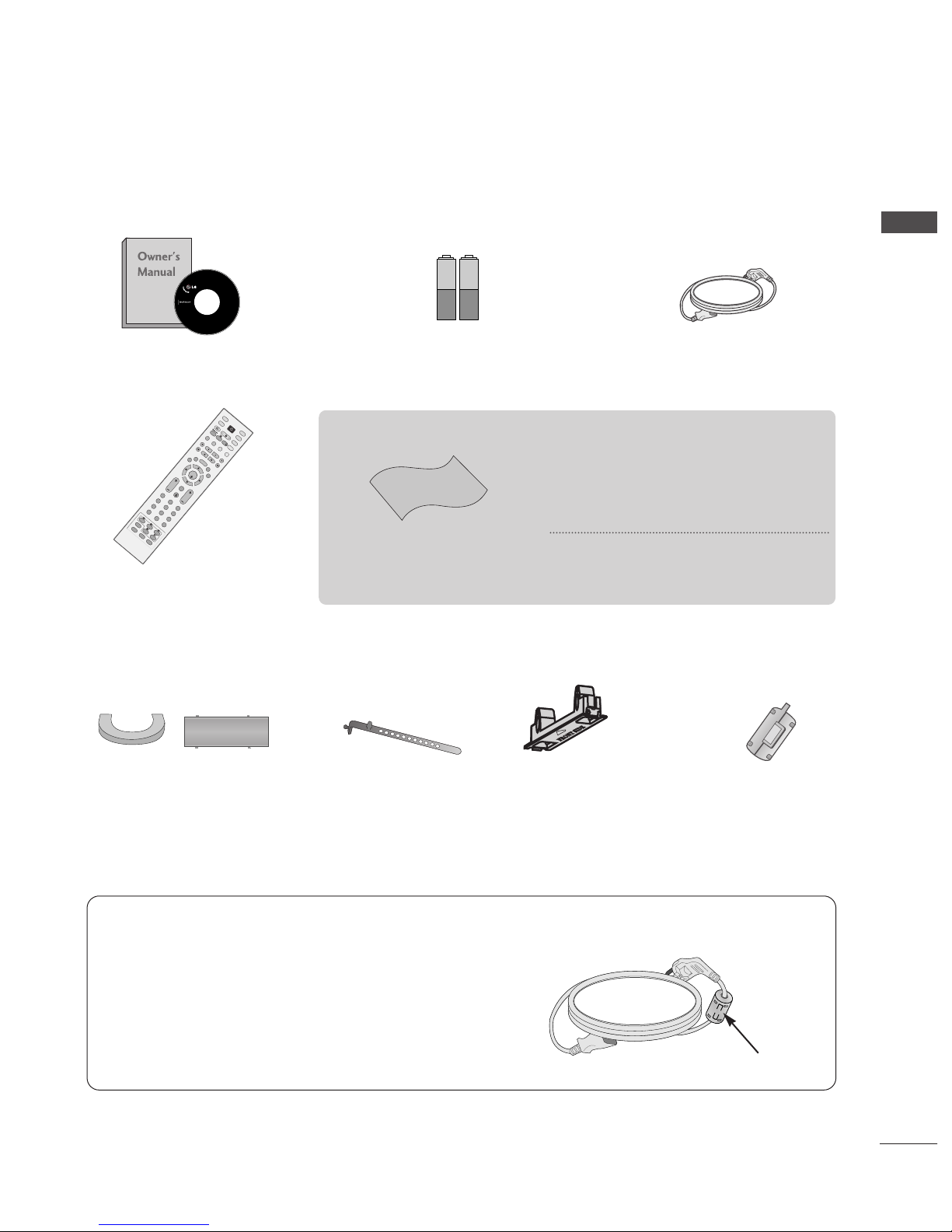
LG 42PG6900 User manual

Please read this manual carefully before operating your
TV.
Retain it for future reference.
Record model number and serial number of the TV.
Refer to the label on the back cover and quote this
information.
To your dealer when requiring service.
PLASMA TV
OWNER’S MANUAL
PLASMA TV MODELS
4422PP6699****
5500PP6699****
ENGLISH
Trademark of the DVB Digital Video
Broadcasting Project (1991 to 1996)
IIDD NNuummbbeerr((ss))::5506: 42P 6900 5508: 50P 6900
5528: 42P 6910 5529: 50P 6910
This product qualifies for ENER Y STAR in the “factory
default (Home mode)” setting and this is the setting in
which power savings will be achieved.
Changing the factory default picture setting or
enabling other features will increase power consump-
tion that could exceed the limits necessary to qualify
for Energy Star rating.


Install the power plug closely.
Use of ferrite core
(This feature is not available for all models.)
Ferrite core can be used to reduce the electromagnetic
wave when connecting the power cord.
The closer the location of the ferrite core to the power
plug, the better it is.
1
ACCESSORIES
ACCESSORIES
Ensure that the following accessories are included with your TV. If an accessory is missing, please contact the
dealer where you purchased the TV.
■
Image shown may differ from your TV.
Owner’s Manual Batteries
OK
INPUT MODE
TV
D/A
DVD
EXIT
TIME
SHIFT
TIME
SHIFT
VOL PR
GUIDE
BACKMENU
DVR
LIVE TV
VCR
POWER
123
456
789
0
Q.VIEW
LIST
INDEX
SLEEP
HOLD
REVEAL
?
SUBTITLE
RATIO
TEXT
INPUT
BRIGHT
MUTE
MARK
TV/RADIO
UPDATE
SIMPLINK
INFO i
FAV
TIME
I/II
Remote Control
Power Cord
Cable management clip
(50PG69** only) (42PG69** only)
Cable Holder Protection cover
(Refer to p.9)
Polishing Cloth
Polishing cloth for use on
the screen.
This feature is not available for all models.
* Lightly wipe any stains or fingerprints on
the surface of the TV with the polishing
cloth.
Do not use excessive force. This may cause
scratching or discolouration.
Ferrite core
(This feature is not available for
all models.)

ACCESSORIES
. . . . . . . . . . . . . . . . . . . . . . . . . . . . . . . . . . . . . . . . . . . . .
1
PREPARATION
Home Menu . . . . . . . . . . . . . . . . . . . . . . . . . . . . . . . 4
Front Panel Controls . . . . . . . . . . . . . . . . . . . . . . . . 5
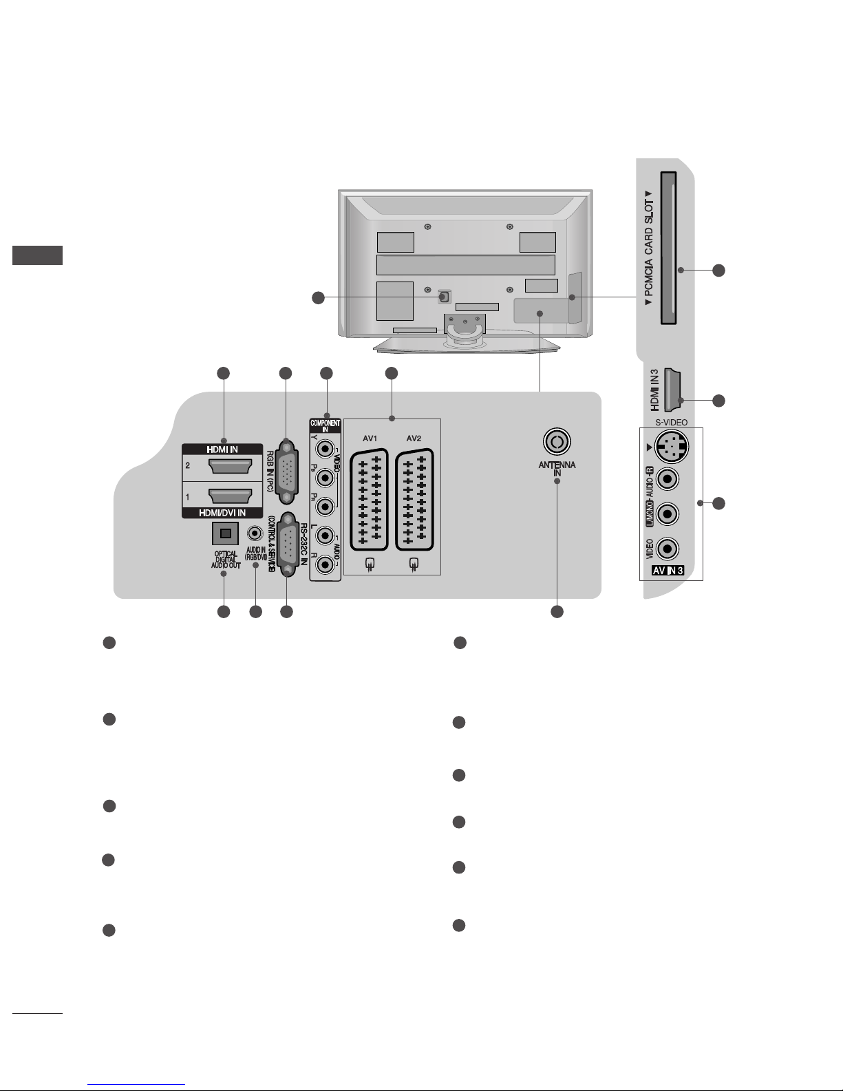
Back Panel Information . . . . . . . . . . . . . . . . . . . . . . 6
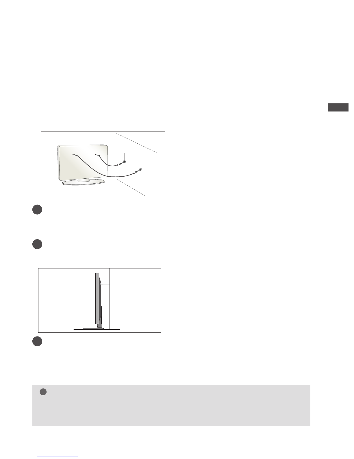
Please set it up carefully so the product does not fall
over. . . . . . . . . . . . . . . . . . . . . . . . . . . . . . . . . . . . . . . 7
Back Cover for Wire Arrangement . . . . . . . . . . . . . . . . . . . . . . . . . . . . .8
Desktop Pedestal Installation . . . . . . . . . . . . . . . . . . 9
Wall Mount: Horizontal installation . . . . . . . . . . . . . 9
Antenna Connection . . . . . . . . . . . . . . . . . . . . . . . . 10
EXTERNAL EQUIPMENT SETUP
HD Receiver Setup . . . . . . . . . . . . . . . . . . . . . . . . 11
DVD Setup . . . . . . . . . . . . . . . . . . . . . . . . . . . . . . . . 13
Insertion of CI module . . . . . . . . . . . . . . . . . . . . . . 15
VCR Setup . . . . . . . . . . . . . . . . . . . . . . . . . . . . . . . . 16
Digital Audio Out Setup . . . . . . . . . . . . . . . . . . . . . 18
Other A/V Source Setup . . . . . . . . . . . . . . . . . . . . 19
PC Setup . . . . . . . . . . . . . . . . . . . . . . . . . . . . . . . . . 20
- Screen Setup for PC Mode . . . . . . . . . . . . . . . 23
WATCHING TV / PROGRAMME CONTROL
Remote Control Key Functions . . . . . . . . . . . . . . . . 27
Turning on the TV . . . . . . . . . . . . . . . . . . . . . . . . . . 29
Programme Selection . . . . . . . . . . . . . . . . . . . . . . . 30
Volume Adjustment . . . . . . . . . . . . . . . . . . . . . . . . 30
On Screen Menus Selection and Adjustment . . . . 31
Auto Programme Tuning (In Digital Mode) . . . . . . 32
Manual Programme Tuning (In Digital Mode) . . . . 33
Programme Edit (In Digital Mode) . . . . . . . . . . . . . 34
5V antenna Power (In Digital Mode only) . . . . . . . 36
Booster (In Digital Mode only) . . . . . . . . . . . . . . . 36
Software Update (In Digital Mode only) . . . . . . . . 37
Diagnostics (In Digital Mode only) . . . . . . . . . . . . 38
CI Information (In Digital Mode only) . . . . . . . . . . 39
Auto Programme Tuning (In Analogue Mode) . . . . . 40
Manual Programme Tuning (In Analogue Mode)
. . . . . . . 41
Fine Tuning (In Analogue Mode) . . . . . . . . . . . . . . 42
Assigning a Station Name (In Analogue Mode)
. . . . . . 42
Programme Edit (In Analogue Mode)
. . . . . . . . . . . . . 43
Selecting the Programme Table . . . . . . . . . . . . . . 45
Input Source Selection . . . . . . . . . . . . . . . . . . . . . 46
SIMPLINK Function . . . . . . . . . . . . . . . . . . . . . . . . 47
DVR (DIGITAL VIDEO RECORDER)
TimeShift Mode ( Pause & Replay of Live TV) . . . 49
Instant Recording . . . . . . . . . . . . . . . . . . . . . . . . . . 52
Manual Recording
. . . . . . . . . . . . . . . . . . . . . . . . . . 55
Recorded TV Programme List . . . . . . . . . . . . . . . . . 56
Schedule List . . . . . . . . . . . . . . . . . . . . . . . . . . . . . . 60
Record Quality . . . . . . . . . . . . . . . . . . . . . . . . . . . . 61
Format Hard Disc . . . . . . . . . . . . . . . . . . . . . . . . . . 62
EPG (Electronic programme guide)(In Digital Mode)
Switch on/off EPG . . . . . . . . . . . . . . . . . . . . . . . . 63
Select a programme . . . . . . . . . . . . . . . . . . . . . . . 63
Button function in NOW/NEXT guide mode . . . 63
Button function in 8 days guide mode . . . . . . . . 64
Button function in date change mode . . . . . . . . 65
Button function in extended description box . . . 65
Record Popup . . . . . . . . . . . . . . . . . . . . . . . . . . . .66
Conflict pop-up . . . . . . . . . . . . . . . . . . . . . . . . . .66
PICTURE CONTROL
Picture Size (Aspect Ratio) Control . . . . . . . . . . . . 67
Preset Picture Settings
- Picture Mode-Preset . . . . . . . . . . . . . . . . . . . . 69
-
Auto Colour Tone Control (Warm/Medium/Cool)
. . . . .70
Manual Picture Adjustment
- Picture Mode-User option . . . . . . . . . . . . . . . . 71
- Colour Tone - User option . . . . . . . . . . . . . . . .72
2
CONTENTS
CONTENTS

XD - Picture Improvement Technology . . . . . . . . . . . . . 73
XD Demo . . . . . . . . . . . . . . . . . . . . . . . . . . . . . . . . . 74
Advanced - Cinema . . . . . . . . . . . . . . . . . . . . . . . . . 75
Advanced - Black(Darkness) Level . . . . . . . . . . . . . 76
Picture Reset . . . . . . . . . . . . . . . . . . . . . . . . . . . . . . 77
Image Sticking Minimization(ISM) Method . . . . . . . . . . 78
Low-Power Picture Mode . . . . . . . . . . . . . . . . . . . . 79
SOUND & LANGUAGE CONTROL
Auto Volume Leveler . . . . . . . . . . . . . . . . . . . . . . . . 80
Preset Sound Settings - Sound Mode . . . . . . . . . . 81
Sound Setting Adjustment - User Mode . . . . . . . . . . 82
Balance . . . . . . . . . . . . . . . . . . . . . . . . . . . . . . . . . . . 83
TV Speakers On/ Off Setup . . . . . . . . . . . . . . . . . . 84
Selecting digital audio out . . . . . . . . . . . . . . . . . . . 85
I/II
-
Stereo/Dual Reception (In Analogue Mode Only)
. . . . 86
-
NICAM Reception (In Analogue Mode Only) . . . . . . .
87
- Speaker Sound Output Selection . . . . . . . . . . 87
On-Screen Menu Language/Country Selection
. . . . . . . . 88
Language selection (In Digital Mode only) . . . . . . .89
TIME SETTING
Clock Setup . . . . . . . . . . . . . . . . . . . . . . . . . . . . . . . 90
Auto On/ Off Timer Setting . . . . . . . . . . . . . . . . . . 91
Auto Shut-off Setting . . . . . . . . . . . . . . . . . . . . . . . 92
Time zone Setup . . . . . . . . . . . . . . . . . . . . . . . . . . . 93
Sleep Timer Setting . . . . . . . . . . . . . . . . . . . . . . . . . 93
PARENTAL CONTROL / RATINGS
Set Password & Lock System . . . . . . . . . . . . . . . . . 94
Parental Control . . . . . . . . . . . . . . . . . . . . . . . . . . . 95
TELETEXT
Switch on/off . . . . . . . . . . . . . . . . . . . . . . . . . . . . . . 96
SIMPLE Text . . . . . . . . . . . . . . . . . . . . . . . . . . . . . . . 96
TOP Text . . . . . . . . . . . . . . . . . . . . . . . . . . . . . . . . . 96
FASTEXT . . . . . . . . . . . . . . . . . . . . . . . . . . . . . . . . . 97
Special Teletext Functions . . . . . . . . . . . . . . . . . . . . 97
DIGITAL TELETEXT
Teletext within Digital Service . . . . . . . . . . . . . . . 98
Teletext in Digital Service . . . . . . . . . . . . . . . . . . 98
APPENDIX
Troubleshooting . . . . . . . . . . . . . . . . . . . . . . . . . . . 99
Maintenance . . . . . . . . . . . . . . . . . . . . . . . . . . . . . 101
Product Specifications . . . . . . . . . . . . . . . . . . . . . 102
Programming the Remote Control . . . . . . . . . . . . 103
IR Codes . . . . . . . . . . . . . . . . . . . . . . . . . . . . . . . . 105
External Control Device Setup . . . . . . . . . . . . . . 107
3
CONTENTS

4
PREPARATION
PREPARATION
HOME MENU
This menu is a contents guide.
In the Home Menu, you can access the Recorded list of the DVR, Manual Recording of the DVR,
Schedule List or the TV Menu.
OK
INPUT MODE
TV
D/A
DVD
EXIT
TIME
SHIFT
TIME
SHIFT
VOL PR
GUIDE
BACK MENU
DVR
LIVE TV
VCR
POWER
TEXT
INPUT
BRIGHT
MUTE
MARK
TV/RADIO
SIMPLINK
INFO i
FAV
Home
Free Space
Programme Guide
Recorded TV
Schedule List
Manual Record
TV Menu
DVR
pp..4499
EPG
pp..6633
TV Menu
pp..3311
This displays the remaining record
time for analogue input. (Analog
TV, AV1,AV2, AV3)
This displays the remaining
record time for DTV input.

5
FRONT PANEL CONTROLS
■
Image shown may differ from your TV.
PREPARATION
PR
VOL
-+
OK
MENU
INPUT
PROGRAMMEVOLUMEMENU OK
INPUT
PR
VOL
-+
OK
MENU
INPUT
Remote Control Sensor
POWER
Power/Standby Indicator
• illuminates red in standby mode.
• illuminates green when the TV is
switched on.
PR
VOL
- +
OK
MENU
INPUT
Swivel Stand
After installing the TV, you can adjust the TV set
manually to the left or right direction by 20 degrees
to suit your viewing position.

Power Cord Socket
This TV operates on an AC power. The voltage is
indicated on the Specifications page. Never
attempt to operate the TV on DC power.
HDMI Input
Connect a HDMI signal to HDMI IN.
Or DVI(VIDEO)signal to HDMI/DVI port with DVI
to HDMI cable.
RGB Input
Connect the output from a PC.
Component Input
Connect a component video/audio device to
these jacks.
Euro Scart Socket (AV1/AV2)
Connect scart socket input or output from an
external device to these jacks.
OPTICAL DIGITAL AUDIO OUT
Connect digital audio from various types of equip-
ment.
Note: In standby mode, these ports do not work.
RGB/DVI Audio Input
Connect the audio from a PC or DTV.
RS-232C IN (CONTROL & SERVICE) PORT
Connect to the RS-232C port on a PC.
Antenna Input
Connect RF antenna to this jack.
PCMCIA (Personal Computer Memory Card
International Association) Card Slot
(This feature is not available in all countries.)
S-Video Input
Connect S-Video out from an S-VIDEO device.
Audio/Video Input
Connect audio/video output from an external
device to these jacks.
6
PREPARATION
BACK PANEL INFORMATION
PREPARATION
■
Image shown may differ from your TV.
1
2
3
4
5
6
7
8
9
10
11
1
10
2
11
2 3 5
4
6 8 97

7
PREPARATION
PLEASE SET IT UP CAREFULLY SO THE PRODUCT
DOESN’T FALL OVER.
■You should purchase necessary components to fix the TV to the wall on the market.
■Position the TV close to the wall to avoid the possibility of it falling when pushed.
■The instructions shown below are a safer way to set up the TV, which is to fix it to the wall, avoiding the possi-
bility of it falling forwards if pulled. This will prevent the TV from falling forward and causing injury. This will
also prevent the TV from damage. Ensure that children do not climb or hang from the TV.
NOTE
!
G When moving the TV undo the cords first.
G Use a platform or cabinet strong and large enough to support the size and weight of the TV.
G To use the TV safely make sure that the height of the bracket on the wall and on the TV is the same.
3
1
2
Use the eye-bolts or TV brackets/bolts to fix the TV to the wall as shown in the picture.
(If your TV has bolts in the eyebolts, loosen these bolts.)
* Insert the eye-bolts or TV brackets/bolts and tighten them securely in the upper holes.
Secure the wall brackets with the bolts on the wall. Match the height of the bracket that is mounted
on the wall.
3Use a sturdy rope to tie the TV. It is safer to tie the rope so it becomes horizontal between the wall
and the TV.
2
1

BACK COVER FOR WIRE ARRANGEMENT
■
Image shown may differ from your TV.
8
PREPARATION
PREPARATION
Connect the cables as necessary.
To connect additional equipment, see the EExxtteerrnnaalleeqquuiippmmeennttSSeettuuppsection.
1
Install the CCAABBLLEEMMAANNAAGGEEMMEENNTTCCLLIIPPas shown.
2
NOTE
!
GGDo not use the CABLE MANAGEMENT CLIP to lift the TV.
- If the TV is dropped, you may be injured or the TV may be damaged.
CABLE MANAGEMENT CLIP
50PG69**
Fix the CCaabblleeHHoollddeerras
shown and bundle the cables.
Hold the CCAABBLLEEMMAANNAAGGEEMMEENNTTCCLLIIPPwith both hands and pull it upward.
For the 42PG69** model, press the center of the CCAABBLLEEMMAANNAAGGEEMMEENNTTCCLLIIPPand then lift it .
How to remove the cable management clip
50PG69**
42PG69**
Separate CABLE MANAGEMENT
from TV by pressing two latches.
42PG69**
CABLE MANAGEMENT CLIP

9
PREPARATION
DESKTOP PEDESTAL INSTALLATION
For adequate ventilation allow a clearance of 4” (10cm) all around the TV.
EARTHING
Ensure that you connect the earth wire to prevent possible
electric shock. Do not try to earth the TV by connecting it
to telephone wires, lightening rods or gas pipes.
Power Supply
Circuit
breaker
■The TV can be installed in various ways such as on a wall or on a desktop etc.
■The TV is designed to be mounted horizontally.
WALL MOUNT: HORIZONTAL INSTALLATION
For adequate ventilation allow a clearance of 4” (10cm) all around the TV. We recommend that you use a
wall mounting bracket of LG brand when mounting the TV to a wall.
4 inches
4 inches
4 inches 4 inches
4 inches
■
Image shown may differ from your TV.
When installing the wall-mounted unit, use the protection
cover for desk-type stand installation.
PPRROOTTEECCTTIIOONNCCOOVVEERRinto the TV until clicking sound.
NOT USING THE DESK-TYPE STAND
4 inches
4 inches 4 inches
4 inches
PR
VOL
-+
OK
MENU
INPUT

AV 1 AV 2
ANTENNA
IN
AV 1 AV 2
ANTENNA
IN
10
PREPARATION
PREPARATION
■For optimum picture quality, adjust antenna direction.
■An antenna cable and converter are not supplied.
■To prevent damage do not connect to the mains outlet until all connections are made between the devices.
Multi-family Dwellings/Apartments
(Connect to wall antenna socket)
Single-family Dwellings /Houses
(Connect to wall jack for outdoor antenna)
Outdoor
Antenna
(VHF, UHF)
Wall
Antenna
Socket
RF Coaxial Wire (75 ohm)
ANTENNA CONNECTION
Antenna
UHF
Signal
Amplifier
VHF
■In poor signal areas, to achieve better picture quality it may be necessary to install a signal amplifier to the
antenna as shown above.
■If signal needs to be split for two TVs,use an antenna signal splitter for connection.
- 5V antenna power works In Digital
mode only. (Refer to p. 36)

11
EXTERNAL EQUIPMENT SETUP
HD RECEIVER SETUP
■This TV can receive Digital RF/Cable signals without an external digital set-top box. However, if you do receive
Digital signals from a digital set-top box or other digital external device, refer to the diagram as shown below.
Connecting with a component cable
Connect the video outputs (Y, PB, PR)of the digital set
top box to the CCOOMMPPOONNEENNTTIINNVVIIDDEEOOjacks on the
TV.
Connect the audio output of the digital set-top box to
the CCOOMMPPOONNEENNTTIINNAAUUDDIIOOjacks on the TV.
Turn on the digital set-top box.
(Refer to the owner’s manual for the digital set-top box.)
Select CCoommppoonneennttinput source using the IINNPPUUTT
button on the remote control.
2
3
4
1
Signal
480i/576i
480p/576p
720p/1080i
1080 p
Component
Yes
Yes
Yes
No
HDMI1/2/3
No
Yes
Yes
Yes
12
■To avoid damaging any equipment, never plug in any power cords until you have finished connecting all equipment.
■
Image shown may differ from your TV.
EXTERNAL EQUIPMENT SETUP

12
EXTERNAL EQUIPMENT SETUP
12
Connect the digital set-top box to HHDDMMII//DDVVIIIINN11
jack on the TV.
Connect the audio output of the digital set-top box to
the AAUUDDIIOOIINN((RRGGBB//DDVVII))jack on the TV.
Turn on the digital set-top box. (Refer to the owner’s
manual for the digital set-top box.)
Select HHDDMMII11input source using the IINNPPUUTTbutton
on the remote control.
2
3
4
1
Connecting a set-top box with an HDMI cable
Connect the digital set-top box to HHDDMMII//DDVVIIIINN11,
HHDDMMIIIINN22or HHDDMMIIIINN33jack on the TV.
Turn on the digital set-top box.
(Refer to the owner’s manual for the digital set-top box.)
Select HHDDMMII11,HHDDMMII22or HHDDMMII33input source using
the IINNPPUUTTbutton on the remote control.
2
3
1
1
Connecting with a HDMI to DVI cable

13
DVD SETUP
Connecting with a component cable
Component Input ports
To achieve better picture quality, connect a DVD player to the component input ports as shown below.
Component ports on the TV
YPBPR
Video output ports
on DVD player
Y
Y
Y
Y
PB
B-Y
Cb
Pb
PR
R-Y
Cr
Pr
Connect the video outputs (Y, PB, PR)of the DVD to the
CCOOMMPPOONNEENNTTIINNVVIIDDEEOOjacks on the TV.
Connect the audio outputs of the DVD to the
CCOOMMPPOONNEENNTTIINNAAUUDDIIOOjacks on the TV.
Turn on the DVD player, insert a DVD.
Select CCoommppoonneennttinput source using the IINNPPUUTTbut-
ton on the remote control.
Refer to the DVD player's manual for operating
instructions.
2
3
4
5
1
1
2
EXTERNAL EQUIPMENT SETUP

14
EXTERNAL EQUIPMENT SETUP
Connecting with a Euro Scart cable
Connect the Euro scart socket of the DVD to the AAVV11
Euro scart socket on the TV.
Turn on the DVD player, insert a DVD.
Select AAVV11input source using the IINNPPUUTTbutton on
the remote control.
If connected to AAVV22Euro scart socket, select AAVV22
input source.
Refer to the DVD player's manual for operating
instructions.
2
3
4
1
(R) AUDIO (L)
AUDIO/
VIDEO
1
NOTE
!
GGAny Euro scart cable used must be signal protected.
Connecting with a S-Video cable
L R
S-VIDEOVIDEO
OUTPUT
SWITCH
ANT IN
ANT OUT
Connect the S-VIDEO output of the DVD to the SS--
VVIIDDEEOOinput on the TV.
Connect the audio outputs of the DVD to the AAUUDDIIOO
input jacks on the TV.
Turn on the DVD player, insert a DVD.
Select AAVV33input source using the IINNPPUUTTbutton on
the remote control.
Refer to the DVD player's manual for operating instruc-
tions.
2
3
4
5
1
12

15
Connecting the HDMI cable
Connect the HDMI output of the DVD to the
HHDDMMII//DDVVIIIINN11, HHDDMMIIIINN22or HHDDMMIIIINN33jack on
the TV.
Select HHDDMMII11,HHDDMMII22or HHDDMMII33input source using
the IINNPPUUTTbutton on the remote control.
Refer to the DVD player's manual for operating
instructions.
1
2
3
Insert the CI Module to PPCCMMCCIIAA(Personal Computer
Memory Card International Association) CCAARRDDSSLLOOTT
of TV as shown.
For further information, see p.39.
1
GGThe TV can receive video and audio signals simultaneously
when using a HDMI cable.
GGIf the DVD player does not support Auto HDMI, you must
TV the output resolution appropriately.
NOTE
!
1
INSERTION OF CI MODULE
TVTV
--TToovviieewwtthheessccrraammbblleedd((ppaayy))sseerrvviicceessiinnddiiggiittaallTTVV
mmooddee..
--TThhiissffeeaattuurreeiissnnoottaavvaaiillaabblleeiinnaallllccoouunnttrriieess..
1
EXTERNAL EQUIPMENT SETUP

16
EXTERNAL EQUIPMENT SETUP
Connecting with a RF cable
■To avoid picture noise (interference), allow adequate distance between the VCR and TV.
■If 4:3 picture format is used for an extended period the fixed images on the sides of the screen may remain
visible.
AUDIO
OUTPUT
SWITCH
ANT IN
R
S-VIDEO VIDEO
ANT OUT L
Wall Jack
Antenna
Connect the AANNTTOOUUTTsocket of the VCR to the AANNTTEENNNNAAIINNsocket on the TV.
Connect the antenna cable to the AANNTTIINNsocket of the VCR.
Press the PPLLAAYYbutton on the VCR and match the appropriate programme between the TV and VCR for
viewing.
VCR SETUP
1
2
2
3
1

17
Connecting with a Euro Scart
Connect the Euro scart socket of the VCR to the AAVV11
Euro scart socket on the TV.
Insert a video tape into the VCR and press PLAY on
the VCR. (Refer to the VCR owner’s manual.)
Select AAVV11input source using the IINNPPUUTTbutton on
the remote control.
If connected to AAVV22Euro scart socket, select AAVV22
input source.
2
3
4
1
AUDIO
(R) AUDIO (L)
AUDIO/
VIDEO
1
NOTE
!
GGAny Euro Scart cable used must be signal shielded.
Connecting with an RCA cable
AUDIO
LR
S-VIDEO VIDEO
OUTPUT
SWITCH
ANT IN
ANT OUT
Connect the AAUUDDIIOO/VVIIDDEEOOjacks between TV and
VCR. Match the jack colours (Video = yellow, Audio Left
= white, and Audio Right = red)
Insert a video tape into the VCR and press PLAY on
the VCR. (Refer to the VCR owner’s manual.)
Select AAVV33input source using the IINNPPUUTTbutton on
the remote control.
1
2
3
GGIf you have a mono VCR, connect the audio cable from the
VCR to the AAUUDDIIOOLL//MMOONNOOjack of the TV.
NOTE
!
1
EXTERNAL EQUIPMENT SETUP

18
EXTERNAL EQUIPMENT SETUP
GGIf both S-VIDEO and VIDEO sockets have been connected to
the S-VHS VCR simultaneously, only the S-VIDEO can be
received.
NOTE
!
AUDIO
L R
S-VIDEOVIDEO
OUTPUT
SWITCH
ANT IN
ANT OUT
Connecting with a S-Video cable
Connect the S-VIDEO output of the VCR to the SS--
VVIIDDEEOOinput on the TV. The picture quality is
improved; compared to normal composite (RCA cable)
input.
Connect the audio outputs of the VCR to the AAUUDDIIOO
input jacks on the TV.
Insert a video tape into the VCR and press PLAY on the
VCR. (Refer to the VCR owner’s manual.)
Select AAVV33input source using the IINNPPUUTTbutton on the
remote control.
2
3
4
1
1 2
DIGITAL AUDIO OUT SETUP
Sending the TV’s audio signal to external audio equipment via the Digital Audio Output (Optical)port.
GDo not look into the optical output port. Looking at the
laser beam may damage your vision.
CAUTION
Connect one end of an optical cable to the TV Digital
Audio (Optical)Output port.
Connect the other end of the optical cable to the digi-
tal audio (optical)input on the audio equipment.
Set the “TV Speaker option - Off” in the AUDIO menu.
(Gpp..8844). Refer to the external audio equipment
instruction manual for operation.
2
3
1
1
2
Other manuals for 42PG6900
1
This manual suits for next models
9
Table of contents
Other LG Plasma TV manuals