LG 50PX4DR - 50 Plasma HDTV User manual

MODELS: 50PY2DR/60PY2E)R/50PX4DR
50PY2DRoUAi60PY2DRoUA/
50PX4DRoUA
of the TV in the
and relate this

Warning/Caution
\
WARNING/CAUTION
WARNING/CAUTION:
TO REDUCE THE RISK OF ELECTRIC SHOCK DO NOT REMOVE COVER (OR BACK), NO USER
SERVICEABLE PARTS INStDE, REFER TO QUALIFIED SERVICE PERSONNEL,
,_ The lightning flash with arrowhead symbo!, within an equilateral triangle, is intended to alert the user to
the presence of uninsulated "dangerous voltage" within the product's enclosure that may be of suffi-
cient magnitude to constitute a risk of electric shock to persons,
The exclamation point within an equilateral triangle is intended to alert the user to the presence ofimportant operating and maintenance (servicing) instructions in the literature accompanying the appli-
ance=
WARNiNG/CAUTiON:
TO PREVENT HRE OR SHOCK HAZARDS, DO NOT EXPOSE THIS PRODUCT TO RAtN OR MOISTURE,
FCC NOTICE
A Class B digita{ device
This equipment has been tested and found to comply with the limits for a Class B digital device, pursuant to Part
15 of the FCC Rules, These limits are designed to provide reasonable protection against harmful interference in
a residential installation, This equipment generates, uses and can radiate radio frequency energy and, if not
installed and used in accordance with the instructions, may cause harmful interference to radio communications,
However, there is no guarantee that interference will not occur in a particular installation, If this equipment does
cause harmful interference to radio or television reception, which can be determined by turning the equipment off
and on, the user is encouraged to try to correct the interference by one or more of the following measures:
- Reorient or relocate the receiving antenna,
- Increase the separation between the equipment and receiver,
- Connect the equipment into an outlet on a circuit different from that to which the receiver is connected,
- Consult the dealer or an experienced radio/TV technician for help,
o Any changes or modifications not expressly approved by the party responsibme for compmi-
ance could void the user's authority to operate the equipment,
CAUTION:
Do not attempt to modify this product in any way without written authorization from LG Electronics, Unauthorized mod-
ification could void the user's authority to operate this product
WARNING/CAUTmON
TO REDUCE THE RISK OF FIRE AND ELECTRIC SHOCK, DO NOT EXPOSE THIS PRODUCT TO
RAIN OR MOISTURE,
2 Plasma TV

Trademark Notice
Aux Etats Unis TV GUIDE et d'autres marques relatives sont des marques depos_es de Gemstar-TV Guide international, Inc.
et/ou d'une de ses soci#t#s affili_es. Au Canada TV GUIDE est une marque d#posee de Transcontinental Inc, utilis#e sous
licence de Gemstar-TV Guide International, Inc.
License Notice
Le syst_me TV Guide On Screen est fabriqu_s sous licence de Gemstar-TV Guide International, Inc. et/ou d'une de ses soci_t6s
affili6es.
Patent Notice
Le systeme TV Guide On Screen est prot#g#s par un ou plusieurs brevets #mis aux Etats Unis, comme le 6,498,895,
6,418,556, 6,331,877; 6,239,794; 6,154,203; 5,940,073; 4,908,713; 4,751,578; 4,706,12!.
Use of the CableCARD TM TradeMark.
"CableCARD TM is a trademark of Cable Television Laboratories Inc."
iity
This digital television is capable of receiving basic analog, digital basic and digital premium cable television programming by
direct connection to a cable system providing such programming. A security card provided by your cable operator is required
to view encrypted digital programming. Cable operator enhanced program (For example, electronic program guide provided
by the cable operator), and data enhanced television service may require the use of a set top box. For more information con-
tact your local cable operator.
Owner's Manual 3

Warning/Caution
iMPORTANT SAFETY iNSTRUCTiONS
Important safety instructions shall be provided with each apparatus. This information shall be given in a separate booklet
or sheet, or be located before any operating instructions in an instruction for installation for use and supplied with the appa-
ratus.
This information shall be given in a language acceptable to the country where the apparatus is intended to be used.
The important safety instructions shall be entitled "Important Safety Instructions". The following safety instructions shall be
included where applicable, and, when used, shah be verbatim as follows. Additional safety information may be included by
adding statements after the end of the following safety instruction list. At the manufacturer's option, a picture or drawing that
illustrates the intent of a specific safety instruction may be placed immediately adjacent to that safety instruction :
1. Read these instructions.
2. Keep these instructions.
3. Heed aH warnings.
4. Follow aH instructions.
5. Do not use this apparatus near water.
6. C_ean only with dry c_oth.
7. Do not b_ock any ventilation openings. Install in accordance with the manufacturer's instructions.
8. Do not install near any heat sources such as radiators, heat registers, stoves, or other apparatus (including amp_i-
tiers)that produce heat.
9. Do not defeat the safety purpose of the polarized or grounding-type p_ug. Apomarized p_ug has two b_ades with
one wider than the other. A grounding type p_ug has two b_ades and a third grounding prong, The wide b_ade or the
third prong are provided for your safety. If the provided p_ug does not fit into your out_et, consult an e_ectrician for
replacement of the obsolete out_et.
10. Protect the power cord from being walked on or pinched particularly at p_ugs, convenience receptacles, and the
point where they exit from the apparatus.
11. Only use attachments/accessories specified by the manufacturer.
12. Use only with the cart, stand, tripod, bracket, or table specified by the manufacturer, or sold with the apparatus.
When a cart is used, use caution when moving the cart/apparatus combination to avoid injury from tip=over.
PORTABLE CART WARNING
J
4 Plasma TV

SafetyInstructions
S
13. Unplug this apparatus during _ightning storms or when unused for _ong periods of time.
14. Refer aH servicing to qualified service personnel Servicing is required when the apparatus has been damaged
in any way, such as power=supply cord or p_ug is damaged, _iquid has been spH_ed or objects have fallen into
the apparatus, the apparatus has exposed to rain or moisture, does not operate normally, or has been dropped.
15. CAUTION concerning the Power Cord :
Most appliances recommend they be p_aced upon a dedicated circuit; that
is, a singme out_et circuit which powers only that appliance and has no
additiona_ out_ets or branch circuits. Check the specification page of
this owner's manua_ to be certain.
Do not overload wall out_ets. Overloaded wall outlets, loose or damaged
wall out_ets, extension cords, frayed power cords, or damaged or
cracked wire insulation are dangerous. Any of these conditions could
result in e_ectric shock or fire. Periodically examine the cord of your
appliance, and if its appearance indicates damage or deterioration,
unplug it, discontinue use of the appliance, and have the cord replaced
with an exact replacement part by an authorized servicer.
Protect the power cord from physica_ or mechanica_ abuse, such as being
twisted, kinked, pinched, c_osed in a door, or walked upon. Pay
particular attention to p_ugs, wall out_ets, and the point where the
cord exits the appliance.
16. Outdoor Use Marking :
WARRmRG -To Reduce The Risk Of Fire Or E_ectrie Shock, Do Not Expose "[his Appliance To Rain Or Moisture.
17. Wet Location Marking :
Apparatus shah not be exposed to dripping or splashing and no objects filled with _iquids, such as vases, shah
be p_aced on the apparatus.
Owner's Manual 5

Contents
C o
Warning/Caution ................................ 2
Digital Cable Compatibility ......................... 3
Safety Instructions ............................. 4-5
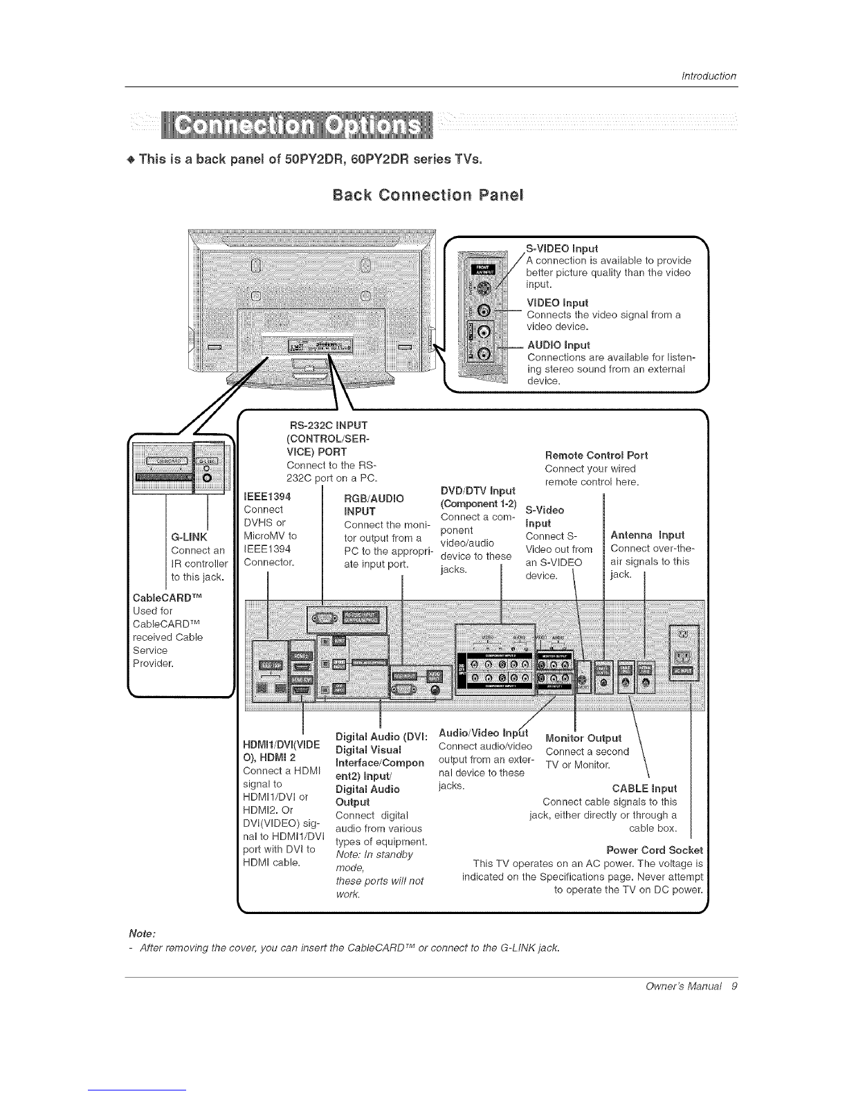
Introduction
Controls/Connection Options ............. 8--11
Remote Control Key Functions .......... 12--13
Installation
Accessories ........................... 14
Installation Instructions
Joining theTV assembly to the wallto protect the set tum-
bling ................................. 14
Install the RING SPACER with the bolts on the set
as shown ............................. 15
Remove or Attache the Plate Cover ........... 17
Swivel function ......................... 18
Arrangement wires ...................... 18
External Equipment Connections .......... 19~28
Antenna or Cable Connection ........... 19-20
VCR Setup ........................... 20
External A/V Source Setup ................ 21
DVD Setup ........................... 21
CabbCARD TM Setup ..................... 22
HDSTB Setup ......................... 22
PC Setup .......................... 23-24
Monitor Out Setup ...................... 28
Digital Audio Output .................... 25
HDMI ............................... 26-28
TV Guide On Screen Setup .............. 29-38
Operation
Turning the TV On ........................ 36
HOME Menu ............................ 37
TV Setup ............................ 38-56
On-screen Menus Language Selection ....... 38
Setup Menu Options
EZ Scan (Channel Search) ................ 39
Manual Scan .......................... 39
Channe! Edit ........................... 40
DTV Signal Strength ..................... 40
Channel Label Setup .................... 41
Main Picture Source Selection ............. 41
Input Label ........................... 41
Video Menu Options
EZ Picture ............................ 42
Manual Picture Control (Custom Option) ...... 42
Color Temperature Control ................ 42
Video Reset ........................... 42
Audio Menu Options
Audio Language ........................ 43
EZ SoundRite /EZ Sound ................. 43
Manual Sound Contro! (custom Option) ....... 44
Front Surround ........................ 44
TV Speakers On/Off Setup ................ 48
Stereo/SAP Broadcasts Setup ............. 48
BBE ................................. 45
Time Menu Options
Auto Clock Setup ....................... 46
Manual Clock Setup ..................... 46
On/Off Timer Setup ..................... 46
Sleep Timer /Auto Off .................... 47
Option Menu Features
Advanced ............................. 48
Cinema 3:2 Mode Setup ................ 48
Low Power .......................... 48
LG Logo ............................ 49
Aspect Ratio Control ..................... 50
Caption ............................... 81
Caption /Text .......................... 51
Caption Option ........................ 52
ISM Method ........................... 53
Front Display .......................... 83
Auto Demo ............................ 54
Lock Menu Options
Parental Lock Setup ..................... 56
CabbCARD TM Function
Cable menu options ..................... 57
Scrambled channel ...................... 87
Cable Channel List ...................... 88
Emergency Alert Message ................ 58
XSTUrJ_
Recorded TV ....................... 58-83
Notes on Memory Card ................ 84-87
Photo List .......................... 88~89
Music List .......................... 70~72
Timeshitt ........................... 73~74
Recording .......................... 78-77
TV Guide On Screen TM System ........... 78~98
[EEE 1394 .......................... 99~110
Remote Control
PIP (Picture-in-Picture)/POP/Twin Picture
Watching PIP/POP/Twin Pbture ............ 111
Selectingan Input Signal Source for PIP/TwinPicture .111
Swapping P!P/Twin Picture ............... 1! 1
TV Program Selection for PIP ............. 111
Moving the PIP sub picture ............... 1!2
AdjustingMain andSub PictureSizes for TwinPicture .f 12
POP (Picture-out-of-Picture: Channel Scan) . .1!2
APM ................................ 113
Bried Info ............................. 114
EZ Mute ............................. 115
Screen Setup for PC mode ............... 116
External Control Device Setup .............. 117~122
IR Codes .............................. 123_4 24
Programming the Remote ..................... 125
Programming Codes ..................... 126_4 27
TrouMeshooting Checklist ..................... 128
Mair_ter_ance ................................ 129
Product Specifications ........................ 130
Warranty ............................... 131_q32
After reading this manual, keep it handy for future reference.
6 P_sma TV

fntroduction
What is a Pmaema Display Panem (PDP)?
A plasma display panel is the latest display technology and the best way to achieve flat panel displays with excellent image quality
and large screen sizes that are easily viewable. The PDP can be thought of as a descendant of the neon lamp and it can be also
be viewed as a series of fluorescent lamps.
Now does it work?
PDP is an array of cells, known as pixels, which are comprised of 3 sub pixels, corresponding to the colors red, green, and blue.
Gas in a plasma state is used to react with phosphors in each sub-pixel to produce colored light (red, green, or blue). These phos-
phors are the same types used in Cathode Ray Tube (CRT) devices such as televisions and common computer monitors.
You get the rich, dynamic colors that you expect. Each sub-pixel is individually controlled by advanced electronics to produce over
16 million different colors. All of these mean that you get perfect images that are easily viewable in a display that is less than 5
inches thick.
160 ° -Wide angBe range of vision
Your flat panel plasma screen offers an exceptionally broad viewing angle -- over 160 degrees. This means that the display is
clear and visible to viewers anywhere in the room who can see the screen.
Wide Screen
The screen of the Plasma Display is so wide that your viewing experience is as if you are in a theater.
Multimedia
Connect your plasma display to a PC and you can use it for conferencing, games, and Internet browsing. The Picture-in-Picture
feature allows you to view "our PC and video images simultaneously.
Vereatime
The light weight and thin size makes it easy to install your plasma display in a variety of locations where conventional TVs will not
fit.
The PDP Manufacturing Process: a few minute coBored dots may be present on the PDP screen
The PDP (Plasma Display Panel), which is the display device of this product, is composed of 0.9 to 2.2 million cells. A few ce!l
defects will normally occur in the PDP manufacturing process. Several tiny, minute colored dots visible on the screen should be
acceptable. This also occurs in other PDP manufacturers' products. The tiny dots appearing does not mean that this PDP is defec-
tive. Thus a few cell defects are not sufficient cause for the PDP to be exchanged or returned. Our production technology mini-
mizes these cell defects during the manufacture and operation of this product.
Cooling Fan Noise
In the same way that a fan is used in a PC computer to keep the CPU (Central Processing Unit) cool, the PDP is equipped with
cooling fans to coo! the Monitor and improve its reliability. Therefore, a certain level of noise could occur while the fans are operat-
ing and cooling the PDR
The fan noise doesn't have any negative effect on the PDP's efficiency or reliability. The noise from these fans is normal during the
operation of this product. We hope you understand that a certain level of noise from the cooling fans is acceptable and is not suffi-
cient cause for the PDP to be exchanged or returned.
Owner's Manual 7

Introduction
÷This is a front panel of 50PY2DR, 60PY2DR series TVs.
- This is a simplified representation of a front panel,
Here shown may be somewhat different from your TV,
- This manual explains the features available on the 50PY2DR, 60PY2DR series TVs,
Front Panel Controls
A
m
Remote Contro_ INDEX Power Standby Indicator
Switches Program Illuminates orange in standby mode,
Sensor LED Display Display When the TV is turned on,
on or off= the indicator will blink green for 3-4
seconds before the picture is seen,
CHANNEL
Buttons
RGB-PC or RGB-DTV'_ mode
IEEE1394 moae
HDMI1/DVI or HDMI2 mgde
Component1 or 2 mode
Antenna or Cable moae
On recording
On playing
State of setting me reserve recora
[_ On operating the XSTU_'_ rnoee
[_ Video or Front Video mode
8 Plasma TV

Introduction
÷ This is a back panel of 50PY2DR, 60PY2DR series TVs.
Back Connection Panel
S-VIDEO mnput
is available to provide
better picture quality than the video
input.
VmDEOmnput
Connects the video signal from a
video device.
put
Connections are available for listen-
ing stereo sound from an external
device.
G=MNK
Connect an
IR controller
to this jack.
CaMeCARD TM
Used for
CableCARD TM
received Cable
Service
Provider=
RS-2320 mNPUT
(CONTROL/SER-
VmCE)PORT
Connect to the RS-
232C port on a PC.
IEEE1394 RGB/AUDIO
Connect iNPUT
DVHS or Connect the moni-
MicroMV to tot output from a
IEEE1394
Connector.
Remote Contro_ Port
Connect your wired
remote control here.
DVD/DTV mnput
(Component 1-2) S=Video
Connect a corn- Input
ponent Connect S-
video/audio
PC to the appropri- device to these Video out from
ate input port. jacks, an S-VIDEO
device.
Antenna Input
Connect over-the-
air signals to this
Digital Audio (DVh Audio/Video InpUt
RDMml/DVI(VIDE Digital Visual Connect audio/video
O), HDMI 2 Interface/Comport output from an exter-
Connect a HDMI ent2) mnput/ nal device to these
signal to Digital Audio jacks.
HDMI1/DVI or Output
HDMI2= Or Connect digital
DVI(VIDEO) sig- audio from various
nal to HDMtl/DVI types of equipment.
)oft with DVI to Note." In standby
HDMI cable, mode,
these ports will not
work.
Monitor Output
Connect a second
TV or Monitor=
CABLE Input
Connect cable signals to this
jack, either directly or through a
cable box=
Power Cord Socket
This TV operates on an AC power= The voltage is
indicated on the Specifications page= Never
to operate the TV on DC power=
Note:
TM
-After removing the cover, you can insert the CableCARD or connect to the G-LINK jack.
Owner's Manual 9

Introduction
÷ This is a front panel of 50PX4DR series TVs.
- This is a simplified representation of front panel.
Here shown may be somewhat different from your TV.
Front Panel: Controls
qeT¢
iiii
_I611AL
[TM
iNDEX
-- Switches
LED
Disolav on
otoff.
CHANNEL (_f, A) Buttons
VOLUME (4,m)Buttons
MENU Button
TV/VIDEO Button
TV GUIDE Button
Remote Contro_
Sensor POWER Button
Power Standby mndicstor
Illuminates orange in standby
mode.
When the TV is turned on,
the indicator will blink green for
3-4 seconds before the picture is
seen.
10 Plasma TV

Introduction
÷ This is a back panel of 50PX4DR series "[Vs.
Back Connection Panel:
S-VmDEO Input
connection is available to provide
better picture quality than the video
input,
VIDEO Input
Connects the video signal from a
video device,
AUDIO mnput
Memory Card Slots
IEEE1394
Connect DVHS or
MicroMV to IEEE1394
Connector,
RGB/AUDIO iNPUT
Connect the monitor output
connector from a PC to the
appropriate input port.
G_LINK TM
Connect an IR
controller to this
jack.
RS-2320 INPUT (CON-
TROL/SERVICE} PORT
Connect to the RS-232C
port on a PC,
DVD/DTV Input
(Component %2)
Connect a component
video/audio device to
these jacks,
Remote Control Port
Connect your wired
remote control here,
S-Video Input
Connect S-
Video out from
an S-VIDEO
device to the S-
VIDEO input,
Antenna mnput
Connect over-the-
air signals to this
_ck.
CaMeCARD TM
Used for
CableCARD TM
received from Cable
Service Provider,
HDM_I/DVL HDMI 2
Digita_ Audio (DVI: Digita_
Visua_
Interface/Component2) Audio/Video In _t
_nput/ Connect audio/video
Digita_ Audio Output output from an
Connect digital audio from external device to
various types of equipment, these jacks,
Connect a HDMI sig- Note: In standby mode,
nal to HDMI1/DVI or these ports will not work.
HDMI2, Or connect a
DVl(Video) signal to
HDMI!/DVI,
Monitor Output
Connect a second
TV or Monitor,
CABLE _nput
Connect cable signals to this
jack, either directly or through
a cable box,
Power Cord Socket
This TV operates on an AC power. The voltage
is indicated on the Specifications page. Never
attempt to operate the TV on DC power.
Owner's Manual 11

fntrodustion
- When using the remote control, aim it at the remote control sensor on the TV.
POWER ......
Turns your TV or any other programmed
equipment on or off, depending on mode.
_Ro
XBTUDIO ....
Bring up the HOME menu to the screen. .........
THUMBSTICK (Up/Down/Left/Right/ENTER)
Allows you to navigate the on-screen menus
and adjust the system settings to your pref-
erence.
RED LIST ..........
Appear the thumbnail recorded list.
VOLUME UP/DOWN ........
Increases/decreases the sound level.
RATIO
Changes the aspect ratio. "\
SAP
Selects MTS sound: Mono, Stereo, and SAP
in Analog mode. Change the audio language
in DTV mode.
CO .... J
Select a closed caption:
Off, CC1 ~4, Text1 ~4.
Remove the Memory Card.
XSTU_C_/VCR/DVD control buttons
/
/• Use for DVR record or trick play.
(Refer to p.61, 74)
Use for Photo mode or Music mode
of X_Tu_'8 . (Refer to p.69, 72)
Controls the DVHS or Camcorder in
IEEE 1394 mode.
Controls some video cassette
recorders or DVD players when you
have already selected DVD or VCR
mode button.
'\ DAY÷/DAY-
Moves the Listings Grid forward or
backward in 24 hour increments.
CHANNEL UP/DOWN
Selects available channels found dur-
ing Manual scan.
PAGE UP/PAGE DOWN
Moves from one full set of screen
information to the next one.
NUMBER buttons
Tunes to the last channel viewed.
Selects the sound appropriate for the
program's character.
APM (Adaptive Picture Mode}
Concurrently, compare with the
Daylight, Normal, Night Time and
Custom on the screen.
(Refer to p.113)
UGHT
illuminates the remote control
buttons of selected
mode.
12 P/asma TV

introduction
TV INPUT
Rotates the input mode between Antenna
and Cable.
Video, Front Video, Component 1-2, RGB-
DTV (or RGB-PC), HDMI1/DV!, HDMI2
and IEEE1394 input sources, screen
returns to the last TV.
MODE
Selects the remote operating mode: TV,
DVD, VCR, AUDIO, CABLE or STB. Select
other operating modes, for the remote to
operate external devices.
MENU
Brings up the main menu to the screen.
Enters or exits a Panel Menu in the TV Guide
On Screen system.
EXmT
Clears all on-screen displays and returns to
TV viewing from any menu.
MUTE
Switches the sound on or off.(Refer to p.115)
TIMER \
Lets you select the amount of time before
your TV turns itself off automatically.
ADJUST
Adiusts screen position, size, and phase in
PC mode.
EZ
Adiusts the factory preset picture
depending on the viewing environment.
AUTO
Starts the demonstration to explain the main
features of this TV.
.......TV/VBDEO
.J" External input modes rotate in regular
sequence: Antenna, Cable, Video, Front
Video, Component 1-2, RGB-DTV (or
RGB-PC), HDMI1/DVl and HDMI2 input
sources.
(Video, Front Video, Component 1-2 input
sources are linked automatically, only if
these are connected )
GUmDE
Brings up the TV Guide On Screen sys-
tem to the screen.
mNFO
...............When you watch the TV, information dis-
plays on top of the screen. Not available
in Component 1-2, RGB, HDMI1/DVl and
HDMI2 mode.(Refer to p.114)
Mark
Selects the wanted functions.
\ FAV
Scrolls the Favorite channels.
PIP
Switches to PIP, POP (Picture-out-of-
Picture) and Twin picture modes in regu-
lar sequence.
Switches the video window locking or
unlocking in the Listings Grid.
PIPCH-/PmPCH+
Changes to the next higher/lower PIP
channel.
PropmNPUT
Selects the input source for the sub pic-
ture in PIP/Twin picture mode.
SWAP
Exchanges the main/sub images in
PIP/Twin picture mode.
Open the battery compartment cover on the back side and install the batteries
matching correct polarity (+ with +, - with -).
install two 1.5V AA batteries. Don't mix old or used batteries with new ones.
Close cover.
Owner's Manua/ 13

/nstaflation
l
Ensure that the following accessories are included with your plasma display. If an accessory is missing, please contact the dealer
where you purchased the product.
Owner's Manual Batteries Remote Control Power Cord
D-sub 15 pin Cable 75£_ Round Cable 2-Wall brackets(50") 2-eye-bolts(50")
G-LINK Cable 6-RING SPACER
(Only 60PY2DR series ) 6- bolts
(Only 60PY2DR series ) 2-Wail brackets(60")
2-TV brackets(60")
- Secure the TV assembly by joining it to a wall by using the TV/Wall brackets.
- Here shown may be somewhat different from your TV.
f _-t ...... --.
(50PY2DR ")
If the set will be mounted on a desk top, insert
the 2 eye-botts and tighten them securely in the upper
holes as shown.
Install the wall brackets on the wall with 2 bolts*, (not
supplied with the product), as shown.
Match the height of the eye-bolts and the wall brack-
ets.
Check to be sure the eye-bolts and the brackets are
tightened securely.
14 Plasma TV

Installation
(" 60PY2_R i!i)
( 50_X4DR :::.'
--... .++-
if the set will be mounted on a desk top, install the 2 ring spac-
er on the TV.
And then install the TV brackets on the ring spacer as shown.
insert the 2 bolts and tighten securely, in the upper holes on
the brackets.
install the wall brackets on the wall with 2 bolts*, (not sup-
plied with the product).
Match the height of the TV brackets and the wall brackets.
Check to be sure the brackets are tightened securely.
Nefe; Bolts and RfNG SPACER commonly use for fixing the
TV bracket or connecting the wall mounting bracket.
I ;
If the set will be mounted on a desk top, insert
the 2 eye-bolts and tighten them securely in the upper
holes as shown.
Install the wall brackets on the wall with 2 bolts*, (not
supplied with the product), as shown.
Match the height of the eye-bolts and the wall brack-
ets.
Check to be sure the eye-bolts and the brackets are
tightened securely.
JJJJ/
./
./
S
J
>/
+ Secure the TV assembly to the wall with strong
strings or wire cables, (not supplied with the prod-
uct), as shown.
1. Put the RING SPACER
in the holes of the bolts
before connecting to
the wal! mounting
bracket.
2. When you connect the
wall mounting bracket
to the set, connect to it
by using the 6-bolts,
(supplied with the
product), as shown.
Nefe; Bolts and RING SPACER commonly use for fixing the TV bracket or connecting the wall mounting bracket.
Owner's Manual 15

fnstaflat/on
The TV can be installed in various ways such as on a wall, or on a desktop etc,
The TV is designed to be mounted horizontally,
- This manual explains the features available on the 50PY2DR, 60PY2DR series TVs,
- Here shown may be somewhat different from your TV,
GROUNDING
Ensure that you connect the earth ground wire to prevent possible
electric shock, if grounding methods are not possible, have a qualified
electrician install a separate circuit breaker, Do not try to ground the
unit by connecting it to telephone wires, lightening rods, or gas pipes,
Power
For proper ventilation, allow a clearance of 4" on each
side and 2" from the wall, Detailed installation instruc-
tions are available from your dealer, see the optional
Wall Mounting Bracket Installation,
For proper ventilation, allow a clearance of 4" on each
side and the top, 2,36" on the bottom, and 2" from the
wall, Detailed installation instructions are included in
the optional Desktop Stand Installation,
i .....
16 Plasma TV

instaflation
- This function explains the features available on the 50PY2DR, 60PY2DR series TVs.
When moving or connecting the power cord, be used the these methods.
And after removing the plate cover, you must install the wall brackets on the wall.
1. With hands, push the lower left/right of plate cover and
then pull out to the front.
2. Connect the power cord on the TV's back.
3. in attaching the plate cover, align the guide to the bush-
ings and press the cover in place with your hand.
Owner's Manual 17

installation
- This function explains the features available on the 50PY2DR, 60PY2DR series TVs.
After installing the TV, you can adiust the the TV set manually turning it to the left or right direction by 20 degrees to suit your
viewing position.
Note: Before adjusting the angle, you must loosen (to the left) the shaft bolt on the middle of stand's back.
And when you acheve the desired position, you must dose the shaft bolt to set the hole.(As shown below)
(. 50/60PY2DR :'!)
--. ........ --
{ 50PX4DR i-
- This function explains the features available on the 50PY2DR, 60PY2DR series TVs.
Run the accessory device wires inside the JACK MANAGEMENT pole as shown.
18 Plasma TV

Installation
1. Analog and Digital TV signals provided on antenna
- Wail Antenna Socket or Outdoor Antenna without a Cable Box Connections
- For optimum picture quality, adjust antenna direction if needed.
SMulti-family DweNings/Apartments
I
I
I
VHF Antenna _i
UHFAntenna
,,ff _*_i_ Outdoor
{+ '_ZZT+r_r.l Antenna
<_ _i Single-family Dwellings/Houses
(Connect to wall jack for outdoor antenna)
Bronze Wire
RF Coaxial Wire (75 ohm) j _
[J
........ f
Turn clockwise to tighten,
Bronze Wire
Be careful not to bend the bronze wire when
connecting the antenna,
2. Analog and Digital TV signals provided on cable
Cable TV Wall Turn clockwise to tighten.
Bronze Wire
Owner's Manual 19

Installation
3. Analog and DigitamTV signals provided on cable and antenna
JAntenna
RF Coaxial Wire (75 ohm)
Bronze Wire
Turn clockwise to tighten.
Cable TV Wall
Jack RF Coaxial Wire (75 ohm)
BronzeWire
To improve the picture quality in a poor signal area,
please purchase a signal amplifier and install properly.
If the antenna needs to be split for two TV's, install a "2-
Way Signal Splitter" in the connections.
If the antenna is not installed properly, contact your deal-
er for assistance.
Note: The TV will let you know when the analog, cable, and digital channel scans are complete.
- To avoid picture noise (interference), leave an adequate distance between the VCR and TV
- Use the ISM Method (on the Option menu) feature to avoid having a fixed image remain on the screen for a long period of
time. If the 4:3 picture format is used; the fixed images on the sides of the screen may remain visible on the screen.
Connection Option 1
Set VCR output switch to 3 or 4 and then tune
TV to the same channel number.
Connection Option 2
1. Connect the audio and video cables from the
VCR's output jacks to the TV input jacks, as
shown in the figure.
When connecting the TV to VCR, match the
iack colors (Video = yellow, Audio Left = white,
and Audio Right = red).
If you connect an S-VIDEO output from VCR
to the S-VIDEO input, the picture quality is
improved; compared to connecting a regular
VCR to the Video input.
2. Insert a video tape into the VCR and press
PLAY on the VCR. (Refer to the VCR owner's
manual.)
3. Select the input source with using the
TV/WDEO button on the remote control. (If
connected to A/V iNPUT, select Video input
SOUrCe)
,_ Do not connect to both Video and
S-Video at the same time.
VCR Rear
20 Plasma TV
This manual suits for next models
6
Table of contents
Other LG Plasma TV manuals
Popular Plasma TV manuals by other brands

Pioneer
Pioneer G-5 Product update guide

Panasonic
Panasonic TH-65XVS30UP operating instructions

Insignia
Insignia NS-42P650A11 user guide

Magnavox
Magnavox 42MF237S - 42" Digital Plasma Hdtv user manual

Panasonic
Panasonic Viera TC-42PX24 operating instructions

Panasonic
Panasonic Viera TH-P50V10D operating instructions