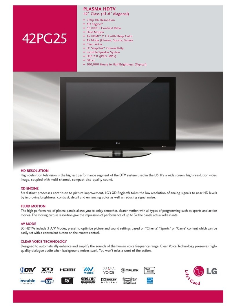
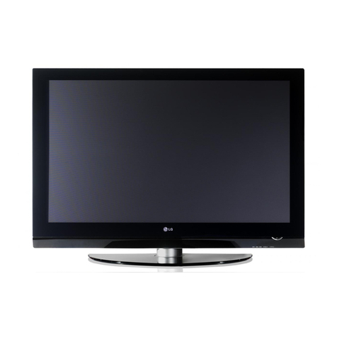
LG 50PA4500 User manual

North/Latin North/Latin
America America
http://aic.lgservice.comhttp://aic.lgservice.com
Europe/Africa http://eic.lgservice.comEurope/Africa http://eic.lgservice.com
Asia/Oceania Asia/Oceania
http://biz.lgservice.comhttp://biz.lgservice.com
Internal Use OnlyInternal Use Only
CHASSIS : PB23ACHASSIS : PB23A
MODEL : MODEL :
50P50P
A4500A4500
50PA4500-DM50PA4500-DM
MODEL :MODEL :
50PA451050PA4510
50PA4510-DJ50PA4510-DJ
CAUTIONCAUTION
BEFORE SERVICING THE CHASSIS,BEFORE SERVICING THE CHASSIS,
READ THE SAFETY PRECAUTIONS IN THIS MANUAL.READ THE SAFETY PRECAUTIONS IN THIS MANUAL.
PLASMA TVPLASMA TV
SERVICE MANUALSERVICE MANUAL


CONTENTSCONTENTS
CONTENTS CONTENTS
........................................
......................................
......................................
......................................
................. .................
22
SAFETY PRECSAFETY PREC
AUTIONS AUTIONS
......................................
......................................
......................................
............... ...............
33
SPECIFICASPECIFICA
TION TION
......................................
......................................
......................................
......................................
........... ...........
44
ADJUSTMENADJUSTMEN
T T
INSTRUCINSTRUC
TION ..............................TION ..............................
......................................
............... ...............
55
BLOCK DIAGRAMBLOCK DIAGRAM
......................................
......................................
......................................
......................................
...... ......
1212
EXPLODED VIEW EXPLODED VIEW
......................................
......................................
......................................
......................................
...... ......
1313
SCHEMASCHEMA
TIC TIC
CIRCUIT CIRCUIT
DIAGRAM DIAGRAM
....................................
......................................
......................................
............

Many elMany el
ectrical ectrical
and mechanicand mechanic
al parts al parts
in this in this
chassis chassis
have spechave spec
ial safetyial safety
-related -related
characteristics. characteristics.
These These
parts arparts ar
e identified e identified
by by
in thein the
Schematic Diagram and Schematic Diagram and
Exploded View.Exploded View.
It is essential that these special safety parts should be replaced with the same components as recommended in this manual to preventIt is essential that these special safety parts should be replaced with the same components as recommended in this manual to prevent
Shock, Fire, or other Hazards.Shock, Fire, or other Hazards.
Do not modify the original design Do not modify the original design
without permission of manufacturer.without permission of manufacturer.
General GuidanceGeneral Guidance
AnAn
isolation Transformer should always be usedisolation Transformer should always be used
during theduring the
servicing of a receiver whose chassis is not isolated from the ACservicing of a receiver whose chassis is not isolated from the AC
power line. Use a transformer of adequate power rating as thispower line. Use a transformer of adequate power rating as this
protects the technician from accidents resulting in personal injuryprotects the technician from accidents resulting in personal injury
from electrical shocks.from electrical shocks.
It will also protect the receiver and it's components from beingIt will also protect the receiver and it's components from being
damaged by accidental shorts of the circuitry that may bedamaged by accidental shorts of the circuitry that may be
inadvertently introduced during the inadvertently introduced during the
service operation.service operation.
If any fuse (or Fusible Resistor) in this TV receiver is blown,If any fuse (or Fusible Resistor) in this TV receiver is blown,
replace it with the specified.replace it with the specified.
When replacing a high When replacing a high
wattage resistor (Oxide Metal Film Resistor,wattage resistor (Oxide Metal Film Resistor,
over 1 W), keep the over 1 W), keep the
resistor 10 mm away from PCB.resistor 10 mm away from PCB.
Keep wires away from high voltage or Keep wires away from high voltage or
high temperature parts.high temperature parts.
Before returning the receiver to the Before returning the receiver to the
customer,customer,
Leakage Current Hot CheckLeakage Current Hot Check
(See below Figure)(See below Figure)
Plug the AC cord directly into the AC outlet.Plug the AC cord directly into the AC outlet.
Do not use a Do not use a
line Isolation Transformline Isolation Transform
er during this check.er during this check.
Connect 1.5 K / 10 watt resistor in parallel with a 0.15 uF capacitorConnect 1.5 K / 10 watt resistor in parallel with a 0.15 uF capacitor
between a known good earth ground (Water Pipe, Conduit, etc.)between a known good earth ground (Water Pipe, Conduit, etc.)
and the exposed metallic parts.and the exposed metallic parts.
Measure the AC voltage across the resistor using AC voltmeterMeasure the AC voltage across the resistor using AC voltmeter
with 1000 ohms/volt with 1000 ohms/volt
or more sensitivity.or more sensitivity.
Reverse plug the AC cord into Reverse plug the AC cord into
the AC outlet and repeat AC voltagethe AC outlet and repeat AC voltage
measurements for each exposed metallic part. Any voltagemeasurements for each exposed metallic part. Any voltage
measured must not exceed 0.75 volt RMS which is corresponds tomeasured must not exceed 0.75 volt RMS which is corresponds to
0.5 mA.0.5 mA.
In case any measurement is out of the limits specified, there isIn case any measurement is out of the limits specified, there is
possibility of shock hazard and the set must be checked andpossibility of shock hazard and the set must be checked and
repaired before it is returned to repaired before it is returned to
the customer.the customer.
Leakage Current Hot Check circuitLeakage Current Hot Check circuit
IMPORTANT SAFETY NOTICEIMPORTANT SAFETY NOTICE
AC Volt-meterAC Volt-meter
SAFETY PRECAUTIONSSAFETY PRECAUTIONS

SPECIFICATIONSPECIFICATION
NOTE : Specifications and others are subject to NOTE : Specifications and others are subject to
change without notice for improvementchange without notice for improvement
..
1. Application range1. Application range
This spec sheet is applied all of the PDP TV with PB23A chassis.This spec sheet is applied all of the PDP TV with PB23A chassis.
2. Requirement for Test2. Requirement for Test
Each part is tested as below without special appointment.Each part is tested as below without special appointment.
(1) Temperature: 25 °C ± 5 °C(77 °F ± 9 °F), CST: 40 °C ± 5 °C(1) Temperature: 25 °C ± 5 °C(77 °F ± 9 °F), CST: 40 °C ± 5 °C
(2) Relative Humidity: 65 % ± 10 %(2) Relative Humidity: 65 % ± 10 %
(3) Power Voltage(3) Power Voltage
: Standard input voltage (AC 100-240 V~, 50/60 Hz): Standard input voltage (AC 100-240 V~, 50/60 Hz)
* Standard Voltage of each products is marked by models.* Standard Voltage of each products is marked by models.
(4) Specification and performance of each parts are followed each drawing and specification by part number in accordance with(4) Specification and performance of each parts are followed each drawing and specification by part number in accordance with
BOM.BOM.
(5) The receiver must be operated for about 5 minutes prior to the adjustment.(5) The receiver must be operated for about 5 minutes prior to the adjustment.
3. Test method3. Test method
(1) Performance: LGE TV test method followed(1) Performance: LGE TV test method followed
(2) Demanded other specification(2) Demanded other specification
- Safety : CE, IEC specification- Safety : CE, IEC specification
- EMC : CE, IEC- EMC : CE, IEC
4. Model 4. Model
General SpecificationGeneral Specification
NN
oo
II
tt
ee
mm
SpecicationSpecication
RemarkRemark
11
RR
ee
cc
ee
ii
vv
ii
nn
g g
SS
yy
ss
tt
ee
mm
11
) )
DD
VV
BB
--
T T
/ /
NN
TT
SS
CC
44
22
//
55
00
PP
AA
44
55
00
00
--
DD
F F
44
22
//
55
00
PP
AA
44
55
11
00
--
DD
CC
42/50PA4900-DD42/50PA4900-DD
50/60PA6500-DA50/60PA6500-DA

ADJUSTMENT INSTRUCTION
1. Application Range
This spec. sheet applies to PB23A chassis applied PDP TV all
models manufactured in TV factory.
2. Specification
(1) Because this is not a hot chassis, it is not necessary to
use an isolation transformer. However, the use of isolation
transformer will help protect test instrument.
(2)
Adjustment must be
done in the correc
t order. But it is
flexible when its factory local problem occurs.
(3) T
he adjustment must be performed in the circumstance of
25 °C ± 5 °C of temperature and 65 % ± 10 % of relative
humidity if there is no specific designation.
(4) The input voltage of the receiver must keep AC 100-240
V~, 50/60 Hz.
(5) Before adjustment, execute Heat-Run for 5 minutes.
■
Afte
r
Rec
eiv
e
100%
Ful
l
whi
te
pat
ter
n
(06
CH)
then
process Heat-run
(or “8. Test pattern” condition of Ez-Adjust status)
■
How to make set white pattern
1) Press Power ON button of Service Remocon
2) Press ADJ button of Service remocon. Select “10. Test
pattern” and, after select “White” using navigation
button, and then you can see 100% Full White pattern.
* In this status you can maintain Heat-Run useless any
pattern generator
*
No
tic
e:
if
you mai
ntain
one pic
ture
over 20
minutes
4.
PCB Assembly Adjustmen
t
4.1. Using RS-232C
-
Adjust 3 items at
3.1. PCB assembly adjustments
" 4.1.
■
Adjustment sequence" one after the order.
■
Adjustment sequence
■
Necessary items before Adjustment items
< See ADC Adjustment RS232C Protocol_Ver1.0 >
O
r
d
e
r
c
o
m
m
a
n
d
S
e
t
r
e
s
p
o
n
s
e
1. Inter the
Adjustment
mode
a
a
0
0
0
0
a
0
0
O
K
0
0
x
2. Change the
Source
XB 00 40
XB 00 60
b 00 OK40x (Adjust 480i Comp1 )
(Adjust 1080p Comp1)
b 00 OK60x (Adjust 1080p RGB)
3. Start
Adjustment
ad 00 10
4. Return the
Response
OKx ( Success condition )
NGx ( Failed condition )
5. Read
Adjustment
data
( main )
ad 00 20
( main )
ad 00 30
(main : component1 480i, RGB 1080p)
000000000000000000000000007c007b006dx
(main : component1 1080p)
000000070000000000000000007c00830077x
6. Conrm
Adjustment
ad
00
99
NG
03
00
x (F
ai
le
d c
on
di
ti
on
)
NG 03 01x (Failed condition)
NG 03 02x (Failed condition)
OK 03 03x (Success condition)
7. End of
Adjustment
a
d
0
0
9
0
d
0
0
O
K
9
0
x

5.
Factory Adjustment
-> PB23A : USE INTERNAL ADC(LM1) : using internal pattern.
5.1. Auto Adjust Component 480i/1080p RGB
1080p
■
Summary : Adjustment component 480i/1080i and RGB
1080p is Gain and Black level setting at Analog
to Digital converter, and compensate the RGB
deviation
■
Using instrument
●
Adjustment remocon, 801GF(802B, 802F, 802R) or
MSPG925FA pattern generator
(
It can output 480i/1080i horizontal 100% color bar
pattern signal, and its output level must setting
0.7V±0.1V p-p correctly)
●
You must make it sure its resolution and pattern cause
every instrument can have different setting
●
Adjustment method 480i Comp1, Adjust 1080p Comp1/
RGB (Factory adjustment)
●
ADC 480i Component1 adjustment
* caution : Set Volume 0 after adjustment
5.2. Use Internal ADC(S7R)
-
ADJ(EZ ADJUST)
->
6.ADC
Calibration ->
ADC
Calibration(START)
*
EDID (The Extended Di
splay Identificati
on Data)/DDC
(Display Data Channel) Download.
■
Summary
●
It is established in VESA, for communication between
PC and Monitor without order from user for building
< Adjustment pattern : 480i / 1080p 60Hz Pattern >

■ It only needs to PCM EDID D/L for North America Product.
* Edid data and Model option download(RS232)
■
EDID data (Model name = LG TV)
- RGB HD
- South Centural America _2D_HD HDMI
N
O
E
n
t
e
r
download MODE
EDID data Model
option download
I
t
e
m
d
o
w
n
l
o
a
d
‘
M
o
d
e
I
n
’
d
o
w
n
l
o
a
d
C
M
D
1
A
A
C
M
D
2
A
E
D
a
t
a
0
0
0
0
0
10
When transfer the
Automat
ically down
load
00 FF FF FF FF FF FF 00 1E 6D 01 00 01 01 01 01
01
16 01
03 68 A0 5A 78 0A
EE 91 A3 54
4C 99 26
0F 50 54 A1 08 00 31 40 45 40 61 40 01 01 01 01
01
01 01 01 01 01 64 19 00 40 41 00 26 30 18 88
36
00 B0 84 43 00 00 18 A0 0F 20 00 31
58 1C 20
28
80 14 00 B0 84 43 00
00 1E 00 00 00 FD
00 3A
3E 1E 53 10 00 0A 20 20 20 20 20 20 00 00 00 FC
00 4C 47 20 54 56 0A 20 20 20 20 20 20 20 00 58
00
FF FF FF
FF FF FF 00 1E
6D 01 00
01 01
01 01
01
16 01
03 80 A0 5A 78 0A EE
91 A3 54 4C 99 26
0F 50 54 A1 08 00 31 40 45 40 61 40 01 01 01 01
01
01 01 01 01 01 64 19 00 40 41 00 26 30 18 88
36
00 B0 84 43 00 00 18 A0 0F 20 00 31
58 1C
20
28
80 14 00 B0 84 43 00
00 1E 00 00 00 FD
00 3A
3E 1E 53 10 00 0A 20 20 20 20 20 20 00 00 00 FC
00 4C 47 20 54 56 0A 20 20 20 20 20 20 20 01 3F
02
03 25 F1
4D 10 1F 04 93 05 14 03 02 12 20 22
15
01 26 15 07 50 09 57
07 67 03 0C
00 10 00 80


- South Centural America _2D_HD HDMI 2
- South Centural America _2D_HD HDMI 3
- Adjustment Color Temperature(White balance)
■ Using Instruments
● Color Analyzer: CA-210 (CH 10)
- Using LCD color temperature, Color Analyzer (CA-
210) must use CH 10, which Matrix compensated
(White, Red, Green, Blue compensation) with CS-
2100. See the Coordination bellowed one.
● Auto-adjustment Equipment (It needs when Auto-adjust
-
ment – It is availed communicate with RS-232C : Baud
rate: 115200)
● Video Signal Generator MSPG-925F 720p, 216Gray
(Model: 217, Pattern 78)
■ Connection Diagram (Auto Adjustment)
● Using Inner Pattern
●
Using HDMI input
00
FF FF FF
FF FF FF 00 1E
6D 01 00
01 01
01 01
01
16 01
03 80 A0 5A 78 0A EE
91 A3 54 4C 99 26
0F 50 54 A1 08 00 31 40 45 40 61 40 01 01 01 01
01
01 01 01 01 01 64 19 00 40 41 00 26 30 18 88
36
00 B0 84 43 00 00 18 A0 0F 20 00 31 58 1C 20
28
80 14 00 B0 84 43 00
00 1E 00 00 00 FD
00 3A
3E 1E 53 10 00 0A 20 20 20 20 20 20 00 00 00 FC
00 4C 47 20 54 56 0A 20 20 20 20 20 20 20 01 3F
02
03 25 F1
4D 10 1F 04 93 05 14 03 02 12 20 22
15
01 26 15 07 50 09
57 07 67 03 0C
00 10 00 80
2D E3 05 03 01 01 1D 00 72 51 D0 1E 20 6E 28 55
00
40 84 63 00
00 1E 02 3A
80 18 71 38 2D 40 58
2C 45 00 40 84 63 00 00 1E 01 1D 80 18 71 1C 16
20
58 2C
25 00 40 84 63 00 00 9E 00 00 00 00 00
00
00 00 00 00 00 00 00 00 00 00 00 00 00 00 00
00
00 00 00 00 00 00 00 00 00 00 00 00 00 00 24
00
FF FF FF
FF FF FF 00 1E
6D 01 00
01 01
01 01
01
16 01
03 80 A0 5A 78 0A EE
91 A3 54 4C 99 26
0F 50 54 A1 08 00 31 40 45 40 61 40 01 01 01 01


■ RS-232C Command (Commonly apply)
●
When Color temperature (White balance) Adjustment
(Automatically)
- Press “Power only key” of service remocon and operate
automatically adjustment.
- Set BaudRate to 115200.
●
You must start “wb 00 00” and finish it “wb 00 ff”.
●
If it needs, then adjustment “Offset”.
■
White Balance Adjustment (Manual adjustment)
●
Test Equipment: CA-210
- Using PDP color temperature, Color Analyzer (CA-210)
must use CH 10, which Matrix compensated (White, Red,
Green, Blue compensation) with CS-2100. See the
Coordination bellowed one.
●
Manual adjustment sequence is like bellowed one.
- Turn to “Ez-Adjust” mode with press ADJ button of service
remocon.
- Select “10.Test Pattern” with CH+/- button and press
enter. Then set will go on Heat-run mode. Over 30
minutes set let on Heat-run mode.
- Let CA-210 to zero calibration and must has gap more
10cm from center of PDP module when adjustment.
- Press “ADJ” button of service remocon and select
“7.White-Balance” in “Ez-Adjust” then press “
►
” button of
navigation key. (When press “
►
” button then set will go to
full white mode)
- Adjust at three mode (Cool, Medium, Warm)
- If “cool” mode
Let B-Gain to 192 and R, G, B-Cut to 64 and then control
R, G gain adjustment High Light adjustment.
- If “Medium” and “Warm” mode Let R-Gain to 192 and R,
G, B-Cut to 64 and then control G, B gain adjustment
RS-232C COMMAND
[CMD
ID
DAT
A]
Meaning
w
b
0
0
0
0
W
h
i
t
e
B
a
l
a
n
c
e
a
d
j
u
s
t
m
e
n
t
s
t
a
r
t
.
w
b
0
0
1
0
S
t
a
r
t
o
f
a
d
j
u
s
t
g
a
i
n
(Inner white pattern)
w
b
0
0
1
f
E
n
d
o
f
g
a
i
n
a
d
j
u
s
t
w
b
0
0
2
0
S
t
a
r
t
o
f
o
f
f
s
e
t
a
d
j
u
s
t
(Inner white pattern)
b
0
0
2
f
E
n
d
o
f
o
f
f
s
e
t
a
d
j
s
t

●
When tester will measure on Cool condition, adjust W30 on
TV display menu.
●
When tester will measure on medium condition, adjust 0 on
TV display menu.
●
When tester will measure on warm condition, adjust W30 on
TV display menu.
● Using CA-210 Equipment. (10 CH)
- Contrast value: 216 Gray
- Brightness spec.
6. GND and ESD Testing
6.1. Prepare GND and ESD Testing.
■ Check the connection between set and power cord
6.2. Operate GND and ESD auto-test.
■ Fully connected (Between set and power cord) set enter the
Auto-tes
t seque
nce.
■ Connect D-Jack AV jack test equipment.
■ Turn on Auto-controller(GWS103-4)
■ Start Auto GND test.
■ If its result is NG, then notice with buzzer.
■ If its result is OK, then automatically it turns to ESD Test.
■ Operate ESD test
■ If its result is NG, then notice with buzzer.
■ If its result is OK, then process next steps. Notice it with
Good lamp and STOPER Down.
6.3. Check Items.
■ Test Voltage
● GND: 1.5KV/min at 100mA
● Signal: 3KV/min at 100mA
■ Test time: just 1 second.
■ Test point
● GND test: Test between Power cord GND and Signal
cable metal GND.
● ESD test: Test between Power cord GND and Live and
neutral.
■ Leakage current: Set to 0.5mA(rms)
6.4. POWER PCB Ass’y Voltage adjustment
Color
temperature
Test
Equipment
Color Coordination
x
y
C
O
O
L
C
A
-
2
1
0
0
.
2
7
6
±
0
.
0
0
2
0
.
2
8
3
±
0
.
0
0
2
M
E
D
I
U
M
C
A
-
2
1
0
0
.
2
8
5
±
0
.
0
0
2
0
.
2
9
3
±
0
.
0
0
2
W
A
R
M
C
A
-
2
1
0
0
.
3
1
3
±
0
.
0
0
2
0
.
3
2
9
±
0
.
0
0
2
I
t
e
m
W
h
i
t
e
a
v
e
r
a
g
e
brightness
Brightness uniformity
M
i
n
4
9
-
2
0
T
y
p
6
0

7. Default Service option.
7.1. ADC-Set.
■ R-Gain adjustment
Value
(default
128)
■ G-Gain adjustment
Value
(default
128)
■ B-Gain adjustment
Value
(default
128)
■ R-Offset adjustment
Value
(default
128)
■ G-Offset
adjustment Value
(default
128)
■ B-Offset
adjustment Value
(default
128)
7.2. White balance. Value.
7.3. Temperature Threshold
■
Threshold
Down
Low
20
■
Threshold
Up
Low
23
■
Threshold
Down
High
70
■
Threshold
Up
High
75
■ Select download le (epk le)
Center(Default)
C
O
O
L
M
i
d
W
a
r
m
R
G
a
i
n
1
9
2
1
9
2
1
9
2
G
G
a
i
n
1
9
2
1
9
2
1
9
2
B
G
a
i
n
1
9
2
1
9
2
1
9
2
R
C
u
t
6
4
6
4
6
4
G
C
u
t
6
4
6
4
6
4
B
C
u
t
6
4
6
4
6
4

BLOCK DIAGRAM

3
0
0
5
2
0
5
8
0
6
0
1
2
0
1
2
0
6
3
0
4
2
0
9
3
0
3
5
4
0
3
1
0
3
0
5
3
0
1
2
0
8
A
9
A
1
2
EXPLODED VIEW
Many electrical and mechanical parts in this chassis have special safety-related characteristics. These
part
s are
identi
fied
by
in
the
Schematic
Diagram
and
EXP
LODE
D VIEW.
It is essential that these special safety parts should be replaced with the same components as
recom
men
ded in this manual to preven
t X-R
ADIATIO
N, S
hock, Fire,
or other Hazards.
Do not modify the original design without permission of manufacturer.
IMPORT
ANT
SAFETY NOTICE


THE
SYMBOL
MARK
OF
THIS
SCHEMETIC
DIAGRAM
INCORPORATES
SP ECI AL FE ATU RES I MPO R TA N T FO R P RO T EC T IO N F ROM X -RA DI A TI O N.
FE_TS_DATA[0]
FE_TS_DATA[1]
FE_TS_DATA[2]
FE_TS_DATA[3]
FE_TS_DATA[4]
FE_TS_DATA[5]
FE_TS_DATA[6]
FE_TS_DATA[7]
BUF1_FE_TS_DATA[7]
BUF1_FE_TS_DATA[6]
BUF1_FE_TS_DATA[5]
BUF1_FE_TS_DATA[4]
FE_TS_DATA[7]
FE_TS_DATA[6]
FE_TS_DATA[5]
FE_TS_DATA[4]
FE_TS_DATA[0]
FE_TS_DATA[1]
FE_TS_DATA[2]
FE_TS_DATA[3]
BUF1_FE_TS_DATA[3]
BUF1_FE_TS_DATA[2]
BUF1_FE_TS_DATA[1]
BUF1_FE_TS_DATA[0]
BUF1_FE_TS_CLK
IF_AGC_MAIN
IF_P_MSTAR
TU_ SDA
R30 1
100
FE_TS_DATA[0-7]
+5V
R31 7
82
A_DEMODE
BUF1_FE_TS_VAL_ERR
Q30 1
MMBT3906(NXP)
A_DEMODE
E
B
C
+1.8V_TU
R30 6
22
FE_TS_VAL_ERR
TU302
TDSS-G101D
DVB_T/C
5
+3.3V
11
DIF [N]
2
RESET
10
DIF [P]
4
SDA
1
NC
9
IF_ AGC
8
CVB S
3
SCL
7
+1.8V
6
SIF
12
SHI ELD
R33 4
0
A_DEMODE
R31 6
470
A_DEMODE
C31 1
0.1uF
16V
TU300
TDSH-T101F
DVB _T_SCA
5
+B1[3.3V]
11
DIF [N]
2
RESET
10
DIF [P]
4
SDA
1
RF_S/W_CTL
9
IF_ AGC
8
CVB S
3
SCL
7
+B2[1.8V]
6
SIF
12
SHI ELD
R32 0
2K
NON_A_DEMODE
TUNER_RESET
FE_TS_DATA[0-7]
R30 2
0
DVB _T2
FE_TS_VAL_ERR
IF_N_MSTAR
C30 1
0.1uF
16V
FNI M
C30 8
0.1uF
16V
A_DEMODE
FE_TS_SYN
C30 5
68p F
50V
R32 7
0
FNI M
C30 6
0.1uF
16V
DVB _T2
+3.3V_TU
TU303
TDSN_B001F
SBTVD
1
RF_S/W_CTL
2
RESET
3
SCL
4
SDA
5
+B1[3.3V]
6
SIF
7
+B2[1.8V]
8
CVB S
9
NC_ 1
10
NC_ 2
11
NC_ 3
12
+B3[3.3V]
13
+B4[1.23V]
14
NC_ 4
15
GND
16
ERROR
17
SYN C
18
VALID
19
MCL K
20
D0
21
D1
22
D2
23
D3
24
D4
25
D5
26
D6
27
D7
28
SHI ELD
C30 3
10u F
16V
TU_ SCL
RF_SWITCH_CTL
C31 3
10p F
50V
READY
TU_CVBS
R30 7
22
BUF1_FE_TS_DATA[0-7]
+3.3V_TU
FE_TS_SYN
R31 0
1K
RF_SWITCH
TU304
TDSN-G301D
DVB _T2
1
NC_ 1
2
RESET
3
SCL
4
SDA
5
+B1[3.3V]
6
SIF
7
+B2[1.8V]
8
CVB S
9
NC_ 2
10
NC_ 3
11
NC_ 4
12
+B3[3.3V]
13
+B4[1.23V]
14
NC_ 5
15
GND
16
ERROR
17
SYN C
18
VALID
19
MCL K
20
D0
21
D1
22
D2
23
D3
24
D4
25
D5
26
D6
27
D7
28
SHI ELD
C30 2
0.1uF
16V
+2.5V_TU
BUF1_FE_TS_SYN
TU_ SIF
C31 2
10p F
50V
READY
C31 0
0.1uF
16V
C30 7
0.1uF
16V
RF_SWITCH
C30 4
68p F
50V
+1.25V_TU
R30 3
0
H_NIM
R30 8
2.2 K
R31 1
10K
R30 9
2.2 K
FE_TS_CLK
R31 2
4.7 K
A_DEMODE
FE_TS_CLK
C30 0
10u F
6.3 V
FNI M
TU302-*1
TDSS-G201D
G201D_NON_DEMODE
5
+B1[3.3V]
11
DIF[N]
2
RESET
10
DIF[P]
4
SDA
1
NC_ 1
9
IF_AGC
8
NC_ 3
3
SCL
7
+B2[1.8V]
6
NC_ 2
12
SHIELD
R32 5
0
FNI M
R32 6
0
FNI M
R32 3
0
FNI M
R32 4
0
FNI M
R33 2
0
FNI M
R33 3
0
FNI M
R33 1
0
FNI M
R32 9
0
FNI M
R33 0
0
FNI M
R32 8
0
FNI M
R32 2
430
NON_A_DEMODE
R31 9
430
NON_A_DEMODE
TU301
TDSS-H201F
ATS C
5
+B1[3.3V]
11
DIF [N]
2
RESET
10
DIF [P]
4
SDA
1
NC_ 1
9
IF_ AGC
8
NC_ 3
3
SCL
7
+B2[1.8V]
6
NC_ 2
12
SHI ELD
Close to Tuner Pin
Close to Tuner Pin
TUNER
TDSS-G201D
TDSS-H201F
TDSH-T101F
TDSN_B001F
TDSN_G301D
T
U
N
E
R
O
P
T
1
OPT2
OPT3
DVB-T/C
ATSC
DVB-T_SCA
SBTVD
DVB_T2
HNIM
HNIM
HNIM
FNIM
FNIM
RF_SW
RF_SW
X
X
X
Close to Tuner Pin
Close to Tuner Pin

Other manuals for 50PA4500
7
This manual suits for next models
3
Table of contents
Other LG Plasma TV manuals