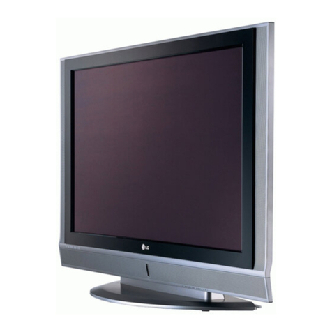
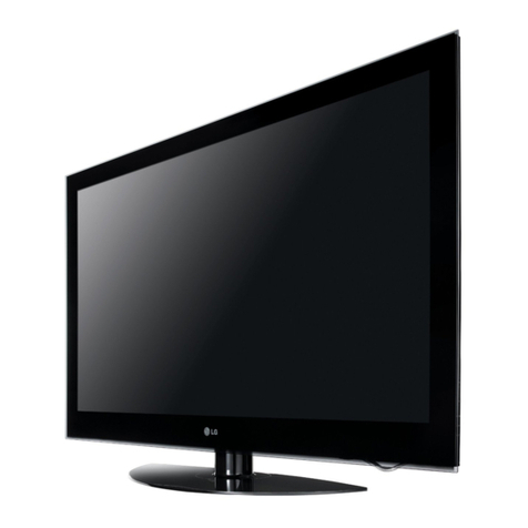
LG 50PC1DR - - 50" Plasma TV User manual

1
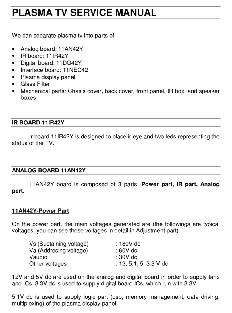
Plasma Display Panel Troubleshooting - 2007
Troubleshooting
50PC1DR

2
Plasma Display Panel Troubleshooting - 2007
Troubleshooting
•Switch Mode Power Supply
•Y SUS Board
•Z SUS Board
•X Drive Boards
Overview of Topics to be
Discussed

3
Plasma Display Panel Troubleshooting - 2007
Safety & Handling Regulations
1. Check the appearance of Panel and boards.
2. Check the model label. Verify model names and board model matches.
3. Check details of defective condition and history.
Ex) COF long 2-1 fail, address 1 line open, Y b/d trouble, Mal-discharge on screen.
1. Approximately 10 minute pre-run time is required before adjustment.
2. Do not exceed Higher voltage than is required for the product.
3. Be cautious of electric shock from the PDP module since the PDP module uses high voltage, and it is
recommended that you should not touch the drive circuits for at least one minute because of residual
current stored.
4. Circuit drive has c-mos circuits which should be protected from static electricity.
5. The PDP Module must be carried by two people.
6. Be careful of short circuit when measuring voltage.
7. Be cautious of screws and other metal objects to prevent short in circuitry.
Checking Point before Requesting MODULE Repair
Safety Rules PLASMA Overview Troubleshooting

4
Plasma Display Panel Troubleshooting - 2007
Switch Mode Power Supply Troubleshooting
This Section of the Presentation will cover troubleshooting the Switch Mode Power Supply for the Single
Scan Plasma. Upon completion of the section the technician will have a better understanding of the operation
of the Power Supply circuit and will be able to locate voltage and test points needed for troubleshooting and
alignments.
•DC Voltages developed on the SMPS
•Adjustments VA, VS, and 5V DC
• Always refer to the sticker located in the upper right side of the PDP for the correct voltage levels
for the DC 5v, VA, VS, V SET UP, -VY, VSC, and Z Bias as they will vary from Panel to Panel.
V SET_UP VSC Z_BIAS
-VY

5
Plasma Display Panel Troubleshooting - 2007
•Define Look at the symptom carefully and determine what circuits could be
causing the failure. Use your senses Sight, Smell, Touch and Hearing. Look for
burned parts and check for possible overheated components. Capacitors will
sometimes leak dielectric material and give off a distinct odor. Frequency of power
supplies will change with the load, or listen for relay closing etc.
• Localize After carefully checking the symptom and determining the circuits to
be checked and after giving a thorough examination using your senses the first check
should always be the DC Supply voltages to those circuits under test. Always confirm
the Supplies are not only the proper level but be sure they are noise free. If the
supplies are missing check the resistance for possible short circuits.
•Isolate To further isolate the failure check for the proper waveforms with the
Oscilloscope to make a final determination of the failure. Look for correct Amplitude
and Timing of the signals also check for the proper Duty Cycle of the signals.
Sometimes “glitches” or “road bumps” will be an indication of an eminent failure.
• Correct The final step is to correct the problem. Be careful of ESD and make
sure to check the DC Supplies for proper levels. Make all necessary adjustments
and lastly always perform a Safety AC Leakage Test before returning the product
back to the Customer.
Troubleshooting Steps

6
Plasma Display Panel Troubleshooting - 2007
SMPS Operating Modes
•Deep Sleep Mode - Guide Plus not programmed or Cable Card not installed
and set is plugged in and turned off. The SMPS outputs S 5v (Standby). Guide Plus has been
programmed the set will remain in Standby Mode when turned off for approximately 2 hours and
go into Deep Sleep Mode. The unit can be taken out of DS Mode as needed for TVGOS Data.
•Standby Operation - Guide Plus has been programmed or a Cable Card is
installed and unit is powered off the SMPS will output 19v,12v, 6v, 5vS, and 3.3v Supplies.
•Full Power On - SMPS outputting all of the Standby Voltages and the
VA, VS, and 5v DC, set in full operation.
Troubleshooting
Power Sequence
• AC Cord Plugged in – Standby 5v
• AC Detect sent from the Power Board Pin1 of P800 to the Digital Board. Needed to enable the
Micro Processor to output the RL-ON Signal to turn on the SMPS.
• Digital Board sends RL-ON to P800 Pin 2 to cause Controller IC U701 on the Power Board to
turn on the Relay Drive Transistors Q701 and Q702 closing the Relays RL101 and RL102 turning
on the 3.3V, 5V, 6V, 12V, and 19V supplies.
• VS-ON applied from the Digital Board to the Power Board on connector P800 Pin 5 used to turn
on the VA, and VS Supplies
• 5V-M Sent from the Digital Board to the Power Board to turn on 5V-DC.
• 5V-D is sent from the Digital Board through P800 Pin 6 and used to bring the Power Supply out of
Deep Sleep Mode.

7
Plasma Display Panel Troubleshooting - 2007
Switch Mode Power Supply (SMPS) Voltages
•VS196v used to drive the Horizontal Grid Voltage, Y SUS, and Z SUS. Measured from pins 8, 9,
and 10 of connector P805 to chassis ground. Adjusted at VR951
•VA
60v used to drive the Vertical Grid Voltage, X Boards and in the IPM Circuits to develop Y and Z
Drive waveforms. Measured from pins 1 and 2 of connector P805 to chassis ground. Adjusted at
VR901
•5v.DC
Used to develop bias voltages for the circuits on the Y SUS, Z SUS, X, and Control Boards.
Measured from pins 1 and 2 of connector P804 to chassis ground.
•3.3v
. Standby voltage applied to the Analog, and Digital Boards to Bias the Signal and Control
circuits. Measured at connector P803 at pins 1 and 2. to chassis ground. Adjusted at VR221.
•19v
Applied to the Analog Board and used for the Audio Output Supply, present in standby.
Measured at P802 pins 1 and 2 to chassis ground.
•12v
Used for supplying low voltage regulators on the Digital and Analog Boards, present in standby.
Measured at P803 pins 9 and 10 to chassis ground.
•6v
Applied to the Digital Board used for the signal processing circuits present in standby. Measured
at P803 pins 5 and 6 to chassis ground.
•S5v
Standby 5 volts at P800 pin 3 applied to the Digital Board.
•VS-ON
Switched 5 volts at P800 pin 5 present after power up to switch on the VA, VS, and 5V on
the Power Board from the Digital Board.
•5v-DSwitched 5v used to bring the Power Supply out of Deep Sleep Mode.
•5V-M
Needed to turn on the 5V-DC Supply.
Troubleshooting

8
Plasma Display Panel Troubleshooting - 2007
Power Supply
Standby Circuit
VA
VS
5v
VS Adjust VA
Adjust
3.3v
Adjust
P802 P803 P800
Troubleshooting
19v Audio Supply
12V,6V, 5V and
3.3V Source
VA Source
VS Source
Control IC
AC Input Circuit
380 Volt Supply

9
Plasma Display Panel Troubleshooting - 2007
Power Supply
Low Voltage Connectors
P800
1) AC-D
2) RL-ON
3) S-5V
4) GND
5) VS-ON
6) 5V-D
7) M5V-ON
8) S-5V
9) GND
10) NC
11) 6V
12) N.C
13) 3.3ON
P800
PIN1
P803
PIN 1
P803
1) 3.3V
2) 3.3V
3) GND
4) GND
5) 6V
6) 6V
7) GND
8) GND
9) 12V
10) 12V
11) GND
12) GND
P802
PIN 1
P802
1) 19V
2) 19V
3) GND
4) GND
5) 6V
6) GND
7) 3.3V
8) GND
9) 12V
10) GND
Troubleshooting

10
Plasma Display Panel Troubleshooting - 2007
TH01
120VAC
Power Supply Voltage Distribution Troubleshooting
AC
INPUT
Circuit
AC
Relay
RL101
AC
Relay
RL102
D101
D102 D501D506
U701
19
24
Low Voltage
Standby Power
Supply
P800
P803
P802
D703 D704
F101
R606
R607
HS1
HS2
L601
Q607
Q606
Q601
Q602
D602
D601
380V
C602 C603
D502
R747
R745
HS3
PCs
T902
U851
U601 Control
IC S-5V
28
Standby
Regulator
T112
R162
U151
R870
U501
AC Input
T901
19V
T801
U801
Q854
Q855
Q151
L851
C855
HS4
PC901
Q801
R963
12V
12V
HS6
T501
3.3V
3.3V
D951
D952
D953
D271
D261
Q252
D251
VS
VA
5V
Q281
6V
6V
6V
Q701
Q702 D202
U261
Q223
D221
S-5V
AC DETECT
RL- ON
VS-ON
3.3v
5V-D
5V-M
5V-M
S-5V
TH02
20

11
Plasma Display Panel Troubleshooting - 2007
• Adjustments
• DC Voltage and Waveform Checks
• Resistance Measurements
Operating Voltages SMPS Supplied VA 60v.
VS 196v.
5v.
YSUS Developed VSC 115v.
-VY -196v.
IPM 18v.
ER IPM
SUS IPM
Ramp UP
V SET DN
V SET UP
Troubleshooting
Y SUSTAIN BOARD Troubleshooting
This Section of the Presentation will cover troubleshooting the Y SUS Board for the Single
Scan Plasma. Upon completion of the Section the technician will have a better
understanding of the operation of the circuit and will be able to locate voltage and
resistance test points needed for troubleshooting and alignments.

12
Plasma Display Panel Troubleshooting - 2007
Important Note
• The following voltages and waveforms should be adjusted in the order they are presented.
• Always adjust the DC levels before the waveform adjustments to most accurately set the Plasma
Display Panel.
Troubleshooting
Voltmeter Adjustments to YSUS
• VSC 115v Used to shape the Y Drive waveform by setting the V Scan level. Measured at the
VSC test points.
•-VY
-196v Used to shape the Y Drive waveform by setting the negative excursion of the V Set
Check Y Sustain Board Output Voltage with the Voltmeter make sure the -VY and VSC are the same
as the Voltage Label on the upper right side of the PDP.
Check VSC Check -VY

13
Plasma Display Panel Troubleshooting - 2007
Waveform Adjustments YSUSTAIN
•RampUp Used to shape the Y Drive Waveform
by changing the pitch of the Top Ramp
•V
SET DN Used to shape the Y Drive
Waveform by changing the pitch of the Bottom
Ramp
•V
SET UP Used to shape the Y Drive
waveform by leveling the Top Ramp
Troubleshooting
14
Plasma Display Panel Troubleshooting - 2007
VSET UP
-VY
RAMP UP
Scope TP
VSET DN +VSCGround
This test point is the
reference for all the following
signals referred to here.
Readings are taken with the
probe set to 10x1.
000
Normal Waveform
Panel Waveform Adjustment
Troubleshooting Single Scan Panel
180 micro seconds
35 micro seconds
*Waveforms may vary with different
Y_SUSTAIN PCB part #’s.

15
Plasma Display Panel Troubleshooting - 2007
Ramp up too low
Ramp up too high Noticeable low level color distortion with the Ramp_up too high.
Noticeable low level color distortion with the Ramp_up too low.
Panel Waveform Adjustment
Troubleshooting Single Scan Panel

16
Plasma Display Panel Troubleshooting - 2007
All of the center washes out due to increased Vset_DN time.
The center begins to wash out and arc due to decreased
Vset DN time.
Vset DN too low
Vset DN too high
Panel Waveform Adjustment
Troubleshooting Single Scan Panel
17
Plasma Display Panel Troubleshooting - 2007
Very little alteration to the picture, the wave form indicates a
distorted Vset UP. The peek widens due to the Vset UP
peeking too quickly.
The center begins to wash out and arc due to Vset UP
Peeking too late and alters the start of the Vset DN phase.
Vset UP too high
Vset UP too low
Panel Waveform Adjustment
Troubleshooting Single Scan Panel
18
Plasma Display Panel Troubleshooting - 2007
The center begins to wash out and arc due to –
VY running to long and clipping.
Colors and the image will bloom slightly and the unit
will have difficulty with clean frame changes in a quickly
altering image.
-VY too low (-154vdc)
-VY too high (-227vdc)
Panel Waveform Adjustment
Troubleshooting Single Scan Panel
19
Plasma Display Panel Troubleshooting - 2007
VSC too low (77 Volts)
VSC too high (140 Volts)
Panel Waveform Adjustment
The image will show very little change but there will
Be some distortion in a quickly changing image.
The image will show very little change but there will
Be some distortion in a quickly changing image.
Troubleshooting Single Scan Panel
20
Plasma Display Panel Troubleshooting - 2007
ZBIAS adjustment: On the Z-Sustain PCB
With the DVM across R92 adjust the potentiometer till the DVM
reads 93 vdc.
DVM
SINGLE SCAN PDP 50PX3
Other manuals for 50PC1DR - - 50" Plasma TV
4
Table of contents
Other LG Plasma TV manuals