LG 32PC5RVC-TB User manual

PLASMA TV
OWNER’S MANUAL
PLASMA TV MODELS
32PC5R*
Please read this manual carefully before operating your set.
Retain it for future reference.
Record model number and serial number of the set.
Refer to the label on the back cover and quote this informa-
tion.
To your dealer when requiring service.
ENGLISH


1
ACCESSORIES
ACCESSORIES
Ensure that the following accessories are included with your TV. If an accessory is missing, please contact the
dealer where you purchased the TV.
Batteries Remote Control Power Cord
2- TV Brackets
2- Wall Brackets
(This feature is not avail-
able for all models.)
2-bolts
(This feature is not available
for all models.)
4-bolts for stand assembly
Refer to p. 6
(This feature is not available for all
models.)
Polishing Cloth
Polishing cloth for use on the screen
This feature is not available
for all models.
*Lightly wipe any stains or fingerprints on the surface of the TV
with the polishing cloth.
Do not use excessive force. This may cause scratching or
discolouration.
Owner's
Manual
Owner’s manual
Owner’s Manual
OK
VOL
PR
PR VOL
I/II
LIST
FAV
SLEEP
Q.VIEW
0
INPUT MUTE
MENU
123
456
789
POWER TV
PIP PR
RATIO EXIT
PIP PR PIP INPUT
?
SIZE
i
TIME HOLD POSITION
REVEAL INDEX TEXT PIP
Holder
(Refer to p.8)
Cover
(Refer to p.10)

PREPARATION
Front Panel Controls................................................. 4
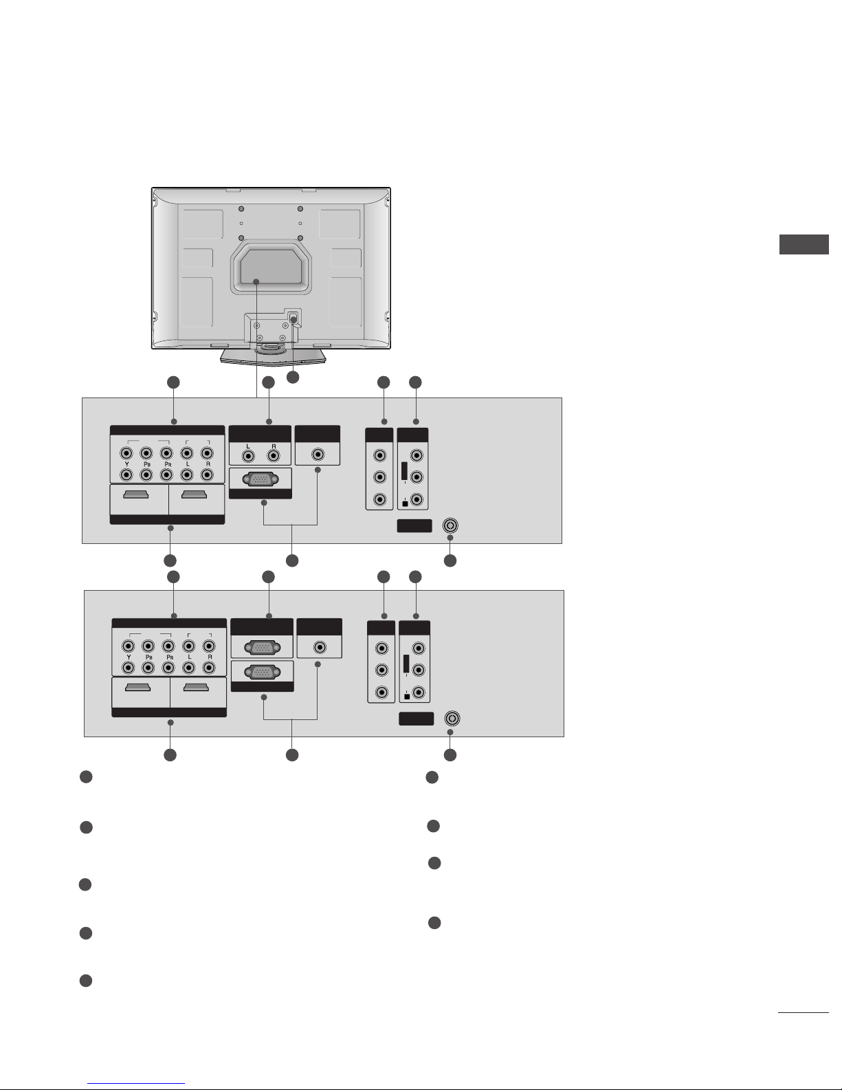
Back Panel Information ............................................ 5
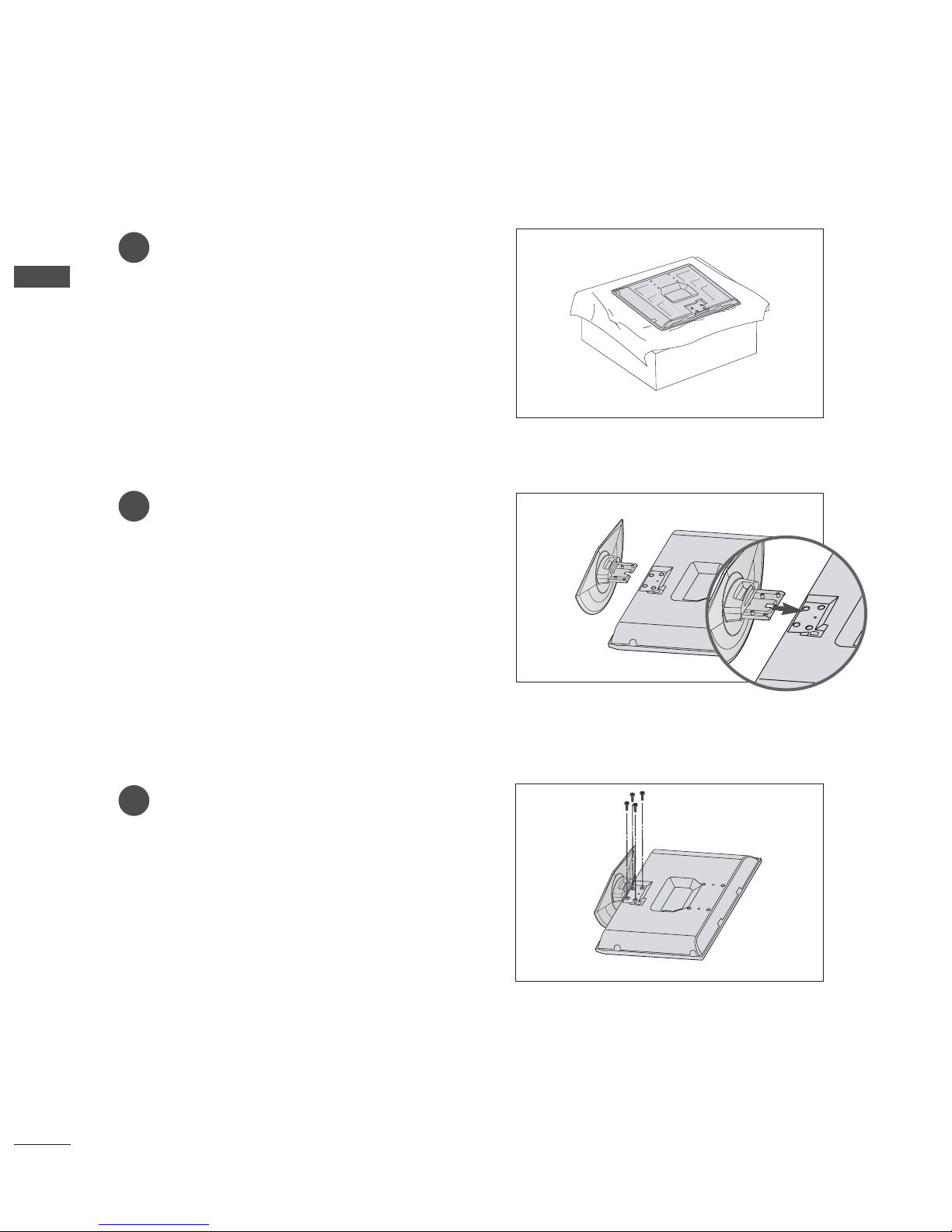
Stand Installation....................................................... 6
Attaching the TV to a Wall........................................7
Back Cover for Wire Arrangement......................... 8
POWER CORD ARRANGEMENT ........................... 8
Desktop Pedestal Installation ................................. 9
Wall Mount: Horizontal installation..................... 10
NOT USING THE DESK-TYPE STAND
....................... 10
Antenna Connection............................................... 11
PICTURE CONTROL
Watching PIP(Picture-in-Picture)..........................43
Picture Size (Aspect Ratio)Control......................45
Preset Picture Settings
- Picture Mode-Preset........................................47
-
Auto Colour Tone Control(Warm/Medium/Cool)
48
Manual Picture Adjustment
- Picture Mode-User Option............................49
- Colour Tone - User Option ...........................50
-
Picture Improvement Technology
................51
Demo .............................................................52
Advanced - Cinema..................................................53
Advanced - Black(Darkness) Level .......................54
Picture Reset..............................................................55
Image Sticking Minimization(ISM) Method........56
Low-Power Picture Mode........................................57
Factory reset
.....................................................................
58
SOUND & LANGUAGE CONTROL
Auto Volume Leveler ....................................................59
Preset Sound Settings - Sound Mode....................60
Sound Setting Adjustment - User Mode ...............61
Balance ............................................................................62
TV Speakers On/Off Setup.......................................63
I/II
- Stereo/Dual Reception.......................................64
- NICAM Reception ................................................65
- Speaker Sound Output Selection....................65
On-Screen Menu Language Selection
...................... 66
EXTERNAL EQUIPMENT SETUP
HD Receiver Setup .......................................................12
DVD Setup..................................................................... 15
VCR Setup ..................................................................... 18
Other A/V Source Setup .......................................... 20
External Stereo............................................................. 21
PC Setup.........................................................................22
- Screen Setup for PC Mode................................24
WATCHING TV /PROGRAMME CONTROL
Remote Control Key Functions..................................28
Turning on the TV....................................................... 30
Programme Selection.................................................. 31
Volume Adjustment ......................................................31
On Screen Menus Selection and Adjustment.......32
Auto Programme Tuning............................................ 33
Manual Programme Tuning ....................................... 34
Fine Tuning .....................................................................35
Assigning a Station Name..........................................36
Programme Edit ........................................................... 37
Favourite Programme .................................................. 38
Selecting the Programme Table............................... 39
Key lock.......................................................................... 40
.................................................................. 41
PREPARATION PICTURE CONTROL
WATCHING TV / PROGRAMME CONTROL
AACCCCEESSSSOORRIIEESS.....................................................1
2
CONTENTS
CONTENTS

3
CONTENTS
APPENDIX
Troubleshooting ............................................................74
Maintenance .................................................................76
Product Specifications ................................................77
TIME SETTING
Clock Setup....................................................................67
Auto On/Off Timer Setting .......................................68
Sleep Timer Setting......................................................69
Auto Shut-off Setting...................................................70
TELETEXT
Switch On/Off ..............................................................71
SIMPLE Text....................................................................71
TOP Text .........................................................................72
FASTEXT .........................................................................72
Special Teletext Functions..........................................73

4
FRONT PANEL CONTROLS
PREPARATION
PREPARATION
■
This is a simplified representation of the front panel. Image shown may differ from your TV.
■
If your TV has a protection film attached, remove the film and then wipe the TV with a polishing cloth.
PR
VOL
OK
MENU
INPUT
Power/Standby Indicator
• illuminates red in standby mode.
• illuminates green when the TV is switched on.
Remote Control
Sensor
PR
VOL
OK
MENU
INPUT
PROGRAMME
VOLUME
MENU
OK
INPUT
POWER
PR
VOL
OK
MENU
INPUT

5
PREPARATION
BACK PANEL INFORMATION
■
This is a simplified representation of the back panel. Image shown may differ from your TV.
VIDEO
AUDIO
COMPONENTCOMPONENT IN
HDMI INHDMI/DVI IN
1 2
RGB IN (PC)RGB IN (PC)
ANTENNA
IN
1
2
VARIABLEARIABLE
OUTOUT
AUDIO INAUDIO IN
(RGB/DVI)(RGB/DVI)
AV OUT
AV IN
L/MONO
R
AUDIO VIDEO
VIDEO
AUDIO
COMPONENT IN
HDMI INHDMI/DVI IN
12
RGB IN (PC)
ANTENNA
IN
1
2
RS-232C IN
(CONTROL & SERVICE)
AUDIO IN
(RGB/DVI)
AV OUT
AV IN
L/MONO
R
AUDIO VIDEO
VIDEO
AUDIO
COMPONENT IN
HDMI INHDMI/DVI IN
12
RGB IN (PC)
ANTENNA
IN
1
2
VARIABLE
OUT
AUDIO IN
(RGB/DVI)
AV OUT
AV IN
L/MONO
R
AUDIO VIDEO
VIDEO
AUDIO
COMPONENT IN
HDMI INHDMI/DVI IN
12
RGB IN (PC)
ANTENNA
IN
1
2
RS-232C IN
(CONTROL & SERVICE)
AUDIO IN
(RGB/DVI)
AV OUT
AV IN
L/MONO
R
AUDIO VIDEO
1 2 3 4
5
8
76
Component Input
Connect a component video/audio device to
these jacks.
Variable Output
Connect an external amplifier or add a subwoofer
to your surround sound system.
(This feature is not available for all models.)
AV Output
Connect second TV or monitor to the AV OUT
socket on the TV.
Audio/Video Input (AV IN)
Connect audio/video output from an external
device to these jacks.
HDMI Input
Connect a HDMI signal to HDMI IN.
Or DVI(VIDEO)signal to HDMI/DVI port with DVI
to HDMI cable.
RGB/Audio Input
Connect the monitor output from a PC to the
appropriate input port.
Antenna Input
Connect RF antenna (UHF) to this jack.
Power Cord Socket
This TV operates on an AC power. The voltage is
indicated on the Specifications page. Never
attempt to operate the TV on DC power.
RS-232C Input (CONTROL&SERVICE) Port
Connect the serial port of the control devices to
the RS-232C jack.
(This feature is not available for all models.)
1
2
3
4
5
6
7
8
9
VIDEO
AUDIO
COMPONENT IN
HDMI INHDMI/DVI IN
12
RGB IN (PC)
ANTENNA
IN
1
2
VARIABLE
OUT
AUDIO IN
(RGB/DVI)
AV OUT
AV IN
L/MONO
R
AUDIO VIDEO
VIDEO
AUDIO
COMPONENTCOMPONENT IN
HDMI INHDMI/DVI IN
1 2
RGB IN (PC)RGB IN (PC)
ANTENNA
IN
1
2
RS-232C INRS-232C IN
(CONTROL(CONTROL & SER& SERVICE)VICE)
AUDIO INAUDIO IN
(RGB/DVI)(RGB/DVI)
AV OUT
AV IN
L/MONO
R
AUDIO VIDEO
1 9 3 4
5 76

6
PREPARATION
PREPARATION
STAND INSTALLATION
1
2
3
Carefully place the TV screen side down on a
cushioned surface to protect the screen from
damage.
Assemble the TV as shown.
Fix the 4 bolts securely using the holes in the
back of the TV.

7
ATTACHING THE TV TO A WALL
(This feature is not available for all models.)
PREPARATION
■Position the TV close to the wall to avoid the possibility of it falling when pushed.
■The instructions shown below are a safer way to set up the TV, which is to fix it to the wall, avoiding the
possibility of it falling forwards if pulled. This will prevent the TV from falling forward and causing injury.
This will also prevent the TV from damage. Ensure that children do not climb or hang from the TV.
NOTE
!
G When moving the TV undo the cords first.
G Use a platform or cabinet string and large enough to support the size and weight of the TV.
G To use the TV safely make sure that the height of the bracket on the wall and on the TV is the same.
2
3
1
1
2
Use the eye-bolts or TV brackets/bolts to fix the TV to the wall as shown in the picture.
(If your TV has bolts in the eyebolts, loosen then bolts.)
* Insert the eye-bolts or TV brackets/bolts and tighten them securely in the upper holes.
Secure the wall brackets with bolts (must purchase seperately) to the wall.
Ensure that both brackets are even.
3Use a strong cord (must purchase separately) to secure the TV.
Secure the cord in such a way that it becomes taught when the TV is in position.

8
PREPARATION
PREPARATION
POWER CORD ARRANGEMENT
After connecting the power cord to the AC input
terminal, remove the bolt at the hole on the back
cover and fix the power cord at the rear side of the
TV by using the bracket for fixing the power cord.
BACK COVER FOR WIRE ARRANGEMENT
Arrange the cables as shown picture.

9
PREPARATION
■The TV can be installed in various ways such as on a wall, or on a desktop etc.
■The TV is designed to be mounted horizontally.
DESKTOP PEDESTAL INSTALLATION
For adequate ventilation allow a clearance of 4” (10cm) all around the TV .
4 inches
4 inches
4 inches 4 inches
Power Supply
Circuit breaker
EARTHING
Ensure that you connect the earth wire to prevent possible electric shock. If grounding methods are not
possible, have a qualified electrician install a separate circuit breaker.
Do not try to earth the TV by connecting it to telephone wires, lightening rods or gas pipes.

10
PREPARATION
PREPARATION
WALL MOUNT: HORIZONTAL INSTALLATION
NOT USING THE DESK-TYPE STAND
For adequate ventilation allow a clearance of 4” (10cm) all around the TV. We recommend that you use a
wall mountin bracket of LG brand when mountin the TV to a wall.
4 inches4 inches
4 inches
4 inches
4 inches
When installin the wall-mounted unit, use the protection
cover for desk-type stand installation.

11
PREPARATION
VIDEO
AUDIO
COMPONENT IN
HDMI INHDMI/DVI IN
12
RGB IN (PC)
ANTENNA
IN
1
2
VARIABLE
OUT
AUDIO IN
(RGB/DVI)
AV OUT
AV IN
L/MONO
R
AUDIO VIDEO
VIDEO
AUDIO
COMPONENT IN
HDMI INHDMI/DVI IN
12
RGB IN (PC)
ANTENNA
IN
1
2
RS-232C IN
(CONTROL & SERVICE)
AUDIO IN
(RGB/DVI)
AV OUT
AV IN
L/MONO
R
AUDIO VIDEO
VIDEO
AUDIO
COMPONENT IN
HDMI INHDMI/DVI IN
12
RGB IN (PC)
ANTENNAANTENNA
IN
1
2
VARIABLE
OUT
AUDIO IN
(RGB/DVI)
AV OUT
AV IN
L/MONO
R
AUDIO VIDEO
VIDEO
AUDIO
COMPONENT IN
HDMI INHDMI/DVI IN
12
RGB IN (PC)
ANTENNA
IN
1
2
RS-232C IN
(CONTROL & SERVICE)
AUDIO IN
(RGB/DVI)
AV OUT
AV IN
L/MONO
R
AUDIO VIDEO
ANTENNA CONNECTION
■For optimum picture quality, adjust antenna direction.
■An antenna cable and converter are not supplied.
Multi-family Dwellings/Apartments
(Connect to wall antenna socket)
Single-family Dwellings /Houses
(Connect to wall jack for outdoor antenna)
Outdoor
Antenna
Wall
Antenna
Socket
RF Coaxial Wire (75 ohm)
Antenna
UHF
Signal
Amplifier
VHF
■In poor signal areas, to achieve better picture quality it may be necessary to install a signal amplifier to the
antenna as shown above.
■If signal needs to be split for two TVs, use an antenna signal splitter for connection.
■
It is recommended that 32PC5RVH model only be used at an altitude of less than 6561 feet (2000m) to get
the best quality picture and sound.
■To prevent damage do not connect to the mains outlet until all connections are made between the devices.

12
EXTERNAL EQUIPMENT SETUP
VIDEOVIDEO
AUDIO
COMPONENTCOMPONENT IN
1 2
RRGB IN (PC)
ANTENNA
IN
1
2
VARIABLE
OUT
AUDIO IN
(RGB/DVI)
AV OUT
AV IN
VIDEO
AUDIO
COMPONENT IN
RGB IN (PC)
ANTENNA
IN
1
2
VARIABLE
OUT
AUDIO IN
(RGB/DVI)
AV OUT
AV IN
12
VIDEO
AUDIO
COMPONENT IN
RGB IN (PC)
ANTENNA
IN
1
2
VARIABLE
OUT
AV OUT
AV IN
12
AUDIO IN
(RGB/DVI)
HDMI INHDMI/DVI IN
HDMI INHDMI/DVI IN
HDMI INHDMI/DVI IN
12
HD RECEIVER SETUP
Connecting with a component cable
Connect the video outputs (Y, PB, PR)of the digital set
top box to the CCOOMMPPOONNEENNTTIINNVVIIDDEEOOjacks on the
TV.
Connect the audio output of the digital set-top box to
the CCOOMMPPOONNEENNTTIINNAAUUDDIIOOjacks on the TV.
Turn on the digital set-top box.
(Refer to the owner’s manual for the digital set-top box.)
Select Component1 input source using the IINNPPUUTT
button on the remote control.
If connected to CCOOMMPPOONNEENNTTIINN22, select
Component2 input source.
2
3
4
1
■To avoid damaging any equipment, never plug in any power cords until you have finished connecting all equipment.
Signal
480i/576i
480p/576p
720p/1080i
Component
Yes
Yes
Yes
HDMI1/2
No
Yes
Yes

13
EXTERNAL EQUIPMENT SETUP
VIDEO
AUDIO
COMPONENT IN
12
RGB IN (PC)
ANTENNA
IN
1
2
VARIABLE
OUT
AUDIO IN
(RGB/DVI)
AV OUT
AV IN
VIDEO
AUDIO
COMPONENT IN
RGB IN (PC)
ANTENNA
IN
1
2
VARIABLE
OUT
AUDIO IN
(RGB/DVI)
AV OUT
AV IN
1 2
VIDEO
AUDIO
COMPONENT IN
RGB IN (PC)
ANTENNA
IN
1
2
VARIABLE
OUT
AV OUT
AV IN
12
AUDIO IN
(RGB/DVI)
HDMI INHDMI/DVI IN
HDMI INHDMI/DVI IN
HDMI INHDMI/DVI IN
1
Connecting a set-top box with an HDMI cable
Connect the HDMI output of the digital set-top box to
the HHDDMMII//DDVVIIIINN11or HHDDMMIIIINN22jack on the TV.
Select HDMI1 or HDMI2 input source using the
IINNPPUUTTbutton on the remote control.
Turn on the digital set-top box.
(Refer to the owner’s manual for the digital set-top box.)
2
3
1
GGTV can receive the video and audio signal simultaneously with using a HDMI cable.
GGIf the digital set-top box supports Auto HDMI function, the output resolution of the source device will
be automatically set to 1280x720p.
GGIf the digital set-top box player does not support Auto HDMI, you need to set the output resolution
appropriately.
To get the best picture quality, adjust the output resolution of the source device to 1280x720p.
NOTE
!

14
EXTERNAL EQUIPMENT SETUP
VIDEO
AUDIO
COMPONENT IN
12
RGB IN (PC)
ANTENNA
IN
1
2
VARIABLE
OUT
AUDIO IN
(RGB/DVI)
AV OUT
AV IN
VIDEO
AUDIO
COMPONENT IN
RGB IN (PC)
ANTENNA
IN
1
2
VARIABLE
OUT
AUDIO IN
(RGB/DVI)
AV OUT
AV IN
12
VIDEOVIDEO
AUDIOAUDIO
COMPONENT IN
RGB IN (PC)
ANTENNAANTENNA
IN
1
2
VARIABLE
OUT
AV OUTV OUT
AV IN
L/MONO
1 2
AUDIO INAUDIO IN
(RGB/DVI)(RGB/DVI)
HDMI INHDMI/DVI IN
HDMI INHDMI/DVI IN
HDMI INHDMI/DVI IN
1
2
Connect the DVI output of the digital set-top box to the HHDDMMII//DDVVIIIINN11jack on the TV.
Connect the audio output of the digital set-top box to the AAUUDDIIOOIINN((RRGGBB//DDVVII))jack on the TV.
Turn on the digital set-top box. (Refer to the owner’s manual for the digital set-top box.)
Select HDMI1 input source using the IINNPPUUTTbutton on the remote control.
2
3
4
1
Connecting with a HDMI to DVI cable

15
EXTERNAL EQUIPMENT SETUP
VIDEO
AUDIO
COMPONENT IN
RGB IN (PC)
ANTENNA
IN
1
2
VARIABLE
OUT
AUDIO IN
(RGB/DVI)
AV OUT
AV IN
12
VIDEO
AUDIO
COMPONENT IN
RGB IN (PC)
ANTENNA
IN
1
2
VARIABLE
OUT
AUDIO IN
(RGB/DVI)
AV OUT
12
AV IN
L/MONO
R
AUDIO VIDEO
VIDEOVIDEO
AUDIO
COMPONENT IN
1 2
RGRGB IN (PC)
ANTENNA
IN
1
2
VVARIABLE
OUT
AUDIO IN
(RGB/DVI)
AV OUT
AV IN
HDMI IN
HDMI/DVI IN
HDMI INHDMI/DVI IN
HDMI INHDMI/DVI IN
1 2
DVD SETUP
Connecting with a component cable
Component Input ports
To achieve better picture quality, connect a DVD player to the component input ports as shown below.
Component ports on the TV
YPBPR
Video output ports
on DVD player
Y
Y
Y
Y
PB
B-Y
Cb
Pb
PR
R-Y
Cr
Pr
Connect the video outputs (Y, PB, PR)of the DVD to the
CCOOMMPPOONNEENNTTIINNVVIIDDEEOOjacks on the TV.
Connect the audio outputs of the DVD to the CCOOMMPPOO--
NNEENNTTIINNAAUUDDIIOOjacks on the TV.
Turn on the DVD player, insert a DVD.
Select
Component1
input source using the IINNPPUUTTbutton
on the remote control.
If connected to CCOOMMPPOONNEENNTTIINN22, select Component2
input source.
Refer to the DVD player's manual for operating instructions.
2
3
4
5
1

16
EXTERNAL EQUIPMENT SETUP
Connecting with a RCA cable
Connect the AAUUDDIIOO/VVIIDDEEOOjacks between TV and DVD
player. Match the jack colours (Video = yellow, Audio Left =
white, and Audio Right = red)
Insert a DVD into the DVD player and press PLAY on the
DVD player. (Refer to the DVD player owner’s manual.)
Select AV input source using the IINNPPUUTTbutton on the
remote control.
2
3
1
LR
S-VIDEO
VIDEO
OUTPUT
SWITCH
ANT IN
ANT OUT
VIDEO
AUDIO
COMPONENT IN
RGB IN (PC)
ANTENNA
IN
1
2
VARIABLE
OUT
AUDIO IN
(RGB/DVI)
AV OUT
AV IN
12
VIDEO
AUDIO
COMPONENT IN
RGB IN (PC)
ANTENNAANTENNA
IN
1
2
VARIABLE
OUT
AUDIO IN
(RGB/DVI)
ATV OUT
12
AV IN
L/L/MONOMONO
R
AUDIOAUDIO VIDEOVIDEO
VIDEO
AUDIO
COMPONENT IN
12
RGB IN (PC)
ANTENNA
IN
1
2
VARIABLE
OUT
AUDIO IN
(RGB/DVI)
AV OUT
AV IN
HDMI IN
HDMI/DVI IN
HDMI INHDMI/DVI IN
HDMI INHDMI/DVI IN
1

17
EXTERNAL EQUIPMENT SETUP
VIDEO
AUDIO
COMPONENT IN
RGB IN (PC)
ANTENNA
IN
1
2
VARIABLE
OUT
AUDIO IN
(RGB/DVI)
AV OUT
AV IN
1 2
VIDEO
AUDIO
COMPONENT IN
RGB IN (PC)
ANTENNA
IN
1
2
VARIABLE
OUT
AUDIO IN
(RGB/DVI)
AV OUT
12
AV IN
L/MONO
R
AUDIO VIDEO
VIDEO
AUDIO
COMPONENT IN
12
RGB IN (PC)
ANTENNA
IN
1
2
VARIABLE
OUT
AUDIO IN
(RGB/DVI)
AV OUT
AV IN
HDMI IN
HDMI/DVI IN
HDMI INHDMI/DVI IN
HDMI INHDMI/DVI IN
1
Connecting the HDMI cable
Connect the HDMI output of the DVD to the
HHDDMMII//DDVVIIIINN11or HHDDMMIIIINN22jack on the TV.
Select HDMI1 or HDMI2 input source using the
IINNPPUUTTbutton on the remote control.
Refer to the DVD player's manual for operating
instructions.
1
GGThe TV can receive video and audio signals simultaneously when
using a HDMI cable.
GG
If the DVD player supports
Auto HDMI function, the output resolu-
tion of the source device will be automatically set to 1280x720p.
GGIf the DVD player does not support Auto HDMI, you must TV the
output resolution appropriately.
To get the best picture quality, adjust the output resolution of the
source device to 1280x720p.
NOTE
!
2
3
Resolution
720x480p
720x576p
128 0x720p
1920x1080i
Supported Display Resolution (HDMI-DTV mode)
Horizontal Vertical
Frequency(kHz) Frequency(Hz)
31.47 59.94
31.50 60.00
31.25 50.00
44.96 59.94
45.00 60.00
37.50 50.00
33.72 59.94
33.75 60.00
28.125 50.00

18
EXTERNAL EQUIPMENT SETUP
OUTPUT
SWITCH
ANT IN
R
S-VIDEO VIDEO
ANT OUT L
VIDEO
AUDIO
COMPONENT IN
RGB IN (PC)
ANTENNA
IN
1
2
VARIABLE
OUT
AUDIO IN
(RGB/DVI)
AV OUT
12
AV IN
L/MONO
R
AUDIO VIDEO
VIDEO
AUDIO
COMPONENT IN
RGB IN (PC)
1
2
VARIABLE
OUT
AUDIO IN
(RGB/DVI)
12
ANTENNA
IN
AV OUT
AV IN
HDMI INHDMI/DVI IN
HDMI INHDMI/DVI IN
Wall Jack
Antenna
1
2
VCR SETUP
Connecting with a RF cable
■To avoid picture noise (interference), allow adequate distance between the VCR and TV.
■Typically a frozen still picture from a VCR. If 4:3 picture format is used for an extended period the fixed
images on the sides of the screen may remain visible.
Connect the AANNTTOOUUTTsocket of the VCR to the AANNTTEENNNNAAIINNsocket on the TV.
Connect the antenna cable to the AANNTTIINNsocket of the VCR.
Press the PPLLAAYYbutton on the VCR and match the appropriate programme between the TV and VCR for
viewing.
1
2
2
3
1
This manual suits for next models
7
Table of contents
Other LG Plasma TV manuals

LG
LG DU-42PY10X User manual

LG
LG 42PY1R-UA User manual

LG
LG 42LG70ER User manual

LG
LG 42PN4500 User manual

LG
LG DT-60PY10 User manual

LG
LG 60PB6500 User manual

LG
LG 60PB660V User manual

LG
LG 50PG20C - - 50" Plasma TV User manual

LG
LG PB56 Series User manual

LG
LG 42PX5D - 42 Plasma Integrated HDTV User manual