LG 60PY3D - - 60" Plasma TV User manual

PLASMA TV
SERVICE MANUAL
CAUTION
BEFORE SERVICING THE CHASSIS,
READ THE SAFETY PRECAUTIONS IN THIS MANUAL.
CHASSIS :PA73A
MODEL : 60PY3D 60PY3DF-UA
CANADA : http//biz.lgservice.com
USA : http//www.lgservice.com
: http//biz.lgservice.com

- 2 -
SAFETY PRECAUTIONS
Many electrical and mechanical parts in this chassis have special safety-related characteristics. These parts are identified by in
the Schematic Diagram and Replacement Parts List.
It is essential that these special safety parts should be replaced ith the same components as recommended in this manual to
prevent X-RADIATION, Shock, Fire, or other Hazards.
Do not modify the original design ithout permission of manufacturer.
General Guidance
An lsolation Transformer should always be used during
the servicing of a receiver hose chassis is not isolated from
the AC po er line. Use a transformer of adequate po er rating
as this protects the technician from accidents resulting in
personal injury from electrical shocks.
It ill also protect the receiver and it's components from being
damaged by accidental shorts of the circuitary that may be
inadvertently introduced during the service operation.
If any fuse (or Fusible Resistor) in this monitor is blo n, replace
it ith the same specified type.
When replacing a high attage resistor (Oxide Metal Film
Resistor, over 1W), keep the resistor 10mm a ay from PCB.
Keep ires a ay from high voltage or high temperature parts.
Leakage Current Cold Check(Antenna Cold Check)
With the instrument AC plug removed from AC source,
connect an electrical jumper across the t o AC plug prongs.
Place the AC s itch in the on positioin, connect one lead of
ohm-meter to the AC plug prongs tied together and touch other
ohm-meter lead in turn to each exposed metallic parts such as
antenna terminals, phone jacks, etc.
If the exposed metallic part has a return path to the chassis, the
measured resistance should be bet een 1MΩ and 5.2MΩ.
When the exposed metal has no return path to the chassis the
reading must be infinite.
An other abnormality exists that must be corrected before the
receiver is returned to the customer.
Leakage Current Hot Check (See belo Figure)
Plug the AC cord directly into the AC outlet.
Do not use a line Isolation Transformer during this check
Connect 1.5K/10 att resistor in parallel ith a 0.15uF capacitor
bet een a kno n good earth ground (Water Pipe, Conduit, etc.)
and the exposed metallic parts.
Measure the AC voltage across the resistor using AC
voltmeter ith 1000 ohms/volt or more sensitivity.
Reverse plug the AC cord into the AC outlet and repeat AC
voltage measurements for each esposed metallic part. Any
voltage measured must not exceed 0.75 volt RMS hich is
corresponds to 0.5mA.
In case any measurement is out of the limits sepcified, there is
possibility of shock hazard and the set must be checked and
repaired before it is returned to the customer.
Leakage Current Hot Check circuit
CANADA: LG Electronics Canada, Inc. 550 Matheson
Boulevard East Mississauga, Ontario L4Z 4G3
USA : LG Customer Interactive Center
P.O.Box 240007, 201 James Record Road Huntsville,
AL 35824
Digital TV Hotline 1-800-243-0000
1.5 Kohm/10W
To Instrument's
exposed
METALLIC PARTS
Good Earth Ground
such as WATER PIPE,
CONDUIT etc.
AC Volt-meter
IMPORTANT SAFETY NOTICE
0.15uF

- 3 -
SPECIFICATIONS.................................................................4
ADJUSTMENT INSTRUCTIONS ..........................................5
BLOCK DIAGRAM...............................................................11
EXPLODED VIEW...............................................................16
EXPLODED VIEW PARTS LIST .........................................17
REPLACEMENT PARTS LIST............................................18
SCHEMATIC DIAGRAM..........................................................
PRINTED CIRCUIT BOARDS.................................................
TABLE OF CONTENTS

- 4 -
SPECIFICATIONS
The specifications shown above may be changed without prior notice for quality improvement.
Width x Height x Depth With Stand
(inches/mm)
Without Stand
Weight (pounds / kg) With Stand
Without Stand
Width x Height x Depth With Stand
(inches/mm)
Without Stand
Weight (pounds / kg) With Stand
Without Stand
Width x Height x Depth With Stand
(inches/mm)
Without Stand
Weight (pounds / kg) With Stand
Without Stand
32LB9D
( 32LB9D-UA)
47LC7DF
( 47LC7DF-UB)
1920 x 1080 (Dot) (Only 32LB9D model:1366 x 768 (Dot))
AC100-240V~ 50/60Hz
NTSC-M, ATSC, 64 & 256 QAM
VHF 2-13, UHF 14-69, CATV 1-135, DTV 2-69, CADTV 1-135
75 Ω
0 ~ 40°C
Less than 80%
-20 ~ 60°C
Less than 85%
60PY3D
( 60PY3DF-UA)
Resolution
Power requirement
Television System
Program Coverage
External Antenna Impedance
Operating Temperature Range
Operating Humidity Range
Storage Temperature Range
Storage Humidity Range
45.1x32.5x12.0 inches
1144.5x825.6x306.0 mm
45.1x29.7x4.1 inches
1144.5x754.5x103.0 mm
82.4 pounds / 37.5 kg
68.9 pounds / 31.3 kg
63.5x40.8x17.8 inches
1613.6x1036.8x452.0 mm
63.5x38.2x3.9 inches
1613.6x970.0x98.5 mm
180.1pounds / 81.7kg
144.8 pounds / 65.7kg
31.7x24.4x11.2 inches
805.8x619.7x283.9 mm
31.7x21.8x3.1 inches
805.8x554.1x79.0 mm
32.4 pounds / 14.7 kg
27.3 pounds / 12.4 kg

1. Application Object
These instructions are applied to all of the PDP TV, PA73A.
2. Notes
(1) Because this is not a hot chassis, it is not necessary to use
an isolation transformer. However, the use of isolation
transformer will help protect test equipment.
(2) Adjustments must be done in the correct order.
(3) The adjustments must be performed in the circumstance of
25±5°C of temperature and 65±10% of relative humidity if
there is no specific designation.
(4) The input voltage of the receiver be must kept 110V, 60Hz
when adjusting.
(5) The receiver must be operational for about 15 minutes
prior to the adjustments.
3. Component 480i/1080p RGB
1080p Adjustment
3-1. Synopsis
Component 480i/1080p RGB 1080p adjustment to set the
black level and the Gain to optimum.
3-2. Test Equipment
(1) Service R/C
(2) 801GF(802B, 802F, 802R) or MSPG925FA Pattern
Generator (480i/1080i The Horizontal 100% Color Bar
Pattern adjust to within 0.7±0.1Vp-p)
[Because the above pattern can differ by the model and
pattern for each device, you must check the pattern first.
3-3. 480i Comp1 Adjustment
(1) Receive the 480i Mode, 100% Horizontal Color Bar
Pattern(HozTV31Bar) to Component 1 port.
(MSPG-925FA: ==> Model : 209, Pattern : 65)
(2) Press the ADJ on the adjustment R/C to enter ‘Ez –
Adjust’. Select ‘1. Adjsut 480i Comp1’ using the
E
and
press the
G
to make the automatic adjustment.
(3) When the adjustment is over, 'ADC Component1 Success’
is displayed. If the adjustment has errors, 'ADC
Component1 408i Fail’ is displayed.
[Fail Message]
- If the component is not connected: Component1 Not
Connected
- If the input format is not 480i: Not Valid Format
- If the input signal is not generated: Check Signal Status
(4) Readjust after confirming the Pattern or adjustment
condition
(5) After adjustment is complete, exit the adjustment mode by
pressing the ADJ.
3-4. 1080p Comp1/RGB Adjustment
(1) Receive the 1080p Mode, 100% Horizontal Color Bar
Pattern(HozTV31Bar) to Component1 and RGB port.
(MSPG-925FA: ==> Model : 225 , Pattern : 65)
(2) After connecting, wait for the image displayed on the
screen
(3) Press the ADJ on the adjustment R/C to enter ‘Ez –
Adjust’. Select ‘2. Adjsut 1080p Comp1/RGB’ using the
E
and press the
G
to make the automatic adjustment.
(4) When the adjustment is over, 'ADC Component1 Success’
is displayed. If the adjustment has errors, 'ADC
Component1 1080p Fail’ is displayed.
(5) When the Component1 adjustment is normally completed,
the RGB adjustment automatically starts.
(6) When the adjustment is over, 'ADC RGB 1080p Success’
is displayed.
(7) When the adjustment has errors, 'ADC RGB 1080p Fail’ is
displayed.
[Fail Message]
- If the component is not connected: Component1 Not
Connected
- If the input format is not 480i: Not Valid Format
- If the input signal is not generated: Check Signal Status
(8) Readjust after confirming the Pattern or adjustment
condition
(9) After adjustment is complete, exit the adjustment mode by
pressing the ADJ.
- 5 -
ADJUSTMENT INSTRUCTIONS
<Fig. 1> ADC Adjustment Pattern:
480i/1080i 60Hz HozTV31Bar Pattern

- 6 -
4. Auto Adjustment of RF and Video
Adjustment of RF and video signal
4-1. Adjustment
(1) Connect the Video Signal Generator (Master) to AV1 port
and input the signal.
Test Equipment: MSPG925FA Pattern Generator
(Model: 201(NTSC-M), Pattern: 33(100% color Bar))
At this time, press the Rev button certainly.
[Because the above pattern can differ by the model, pattern
and rev button for each device, you must check the pattern
first.
(2) Apply the RF signal to the antenna. (Make sure that the
signal is received)
(3) Enter the ‘Ez - Adjust’ by pressing the ADJ on the Service
R/C.
After select the ‘3.Adjust RF and Video’, start the
adjustment by pressing the Right Key(
G
).
When it enters the adjustment mode, the screen is
automatically split as TV 2CH SPLIT as shown at the
below figure.
(4) When the adjustment is over, 'RF Configuration Success’ is
displayed. If the adjustment has errors, 'RF Configuration
Error’ is displayed.
(5) When adjusting the RF signal is completed, it is
automatically switched to the Video mode as shown at the
below figure, and the automatic adjustment for the Video
mode starts.
(6) When the adjustment is over, 'AV Configuration Success’ is
displayed. If the adjustment has errors, 'AV Configuration
Error’ is displayed.
ADJUSTMENT INSTRUCTIONS
<Fig. 2>
<Fig. 3>
<Fig. 4>

- 7 -
ADJUSTMENT INSTRUCTIONS
<HEAT RUN>
OPreliminary action is applied to the test for afterimage
discharge detection, and 100% FULL WHITE PATTERN
must be operated automatically.
(1) Pressing Power On key on the adjustment R/C
(2) Full Test Pattern(2 min 30sec) --> Full Black
Pattern(30sec) --> Full White Pattern
(Full White Pattern when the main power is turned on
again after being turned off)
(3) Pattern Mode is deselected by pressing CH +/-, Exit Key.
[Set is activated HEAT-RUN without signal generator in this
mode.
5. Voltage Adjustment(60” Model)
(1) Va Voltage Adjustment
1) Connect + terminal of D.M.M to Va pin of P805 and
connect – terminal to GND pin of P805.
2) Adjust RV501 voltage to match that of the label on the
Top/Right of the panel. (Deviation : ±0.5V)
(2) Vs Voltage Adjustment
1) Connect + terminal of D.M.M to Vs pin of P805 and
connect – terminal to GND pin of P805.
2) Adjust RV401 voltage to match that of the label on the
Top/Right of the panel. (Deviation : ±0.5V)
6. EDID(The Extended Display
Identification Data)/DDC
(Display Data Channel) Download
It is the feature to implement the “Plug and Play” which
automatically reconfigures the user’sl environment to directly
use by exchanging information without any command directly
to the PC or the monitor by the user, which is established by
the VESA
6-1. Required Test Equipment
(1) PC(S/W: EDID TESTER Ver.2.5)
(2) EDID Download JIG (PC serial to D-sub connection cable)
(3) Connection Cable
Test Pattern 2min 30sec
Test Pattern 30sec
If you turn on a still screen more than 20 minutes (Especially
Digital pattern(13 CH), Cross Hatch Pattern), an afterimage
may occur in the black level part of the screen.
Each PCB Assy must be checked by Check JIG Set before
assembly. (Especially, be careful Power PCB Assy which can
cause Damage to the PDP Module.)

- 8 -
ADJUSTMENT INSTRUCTIONS
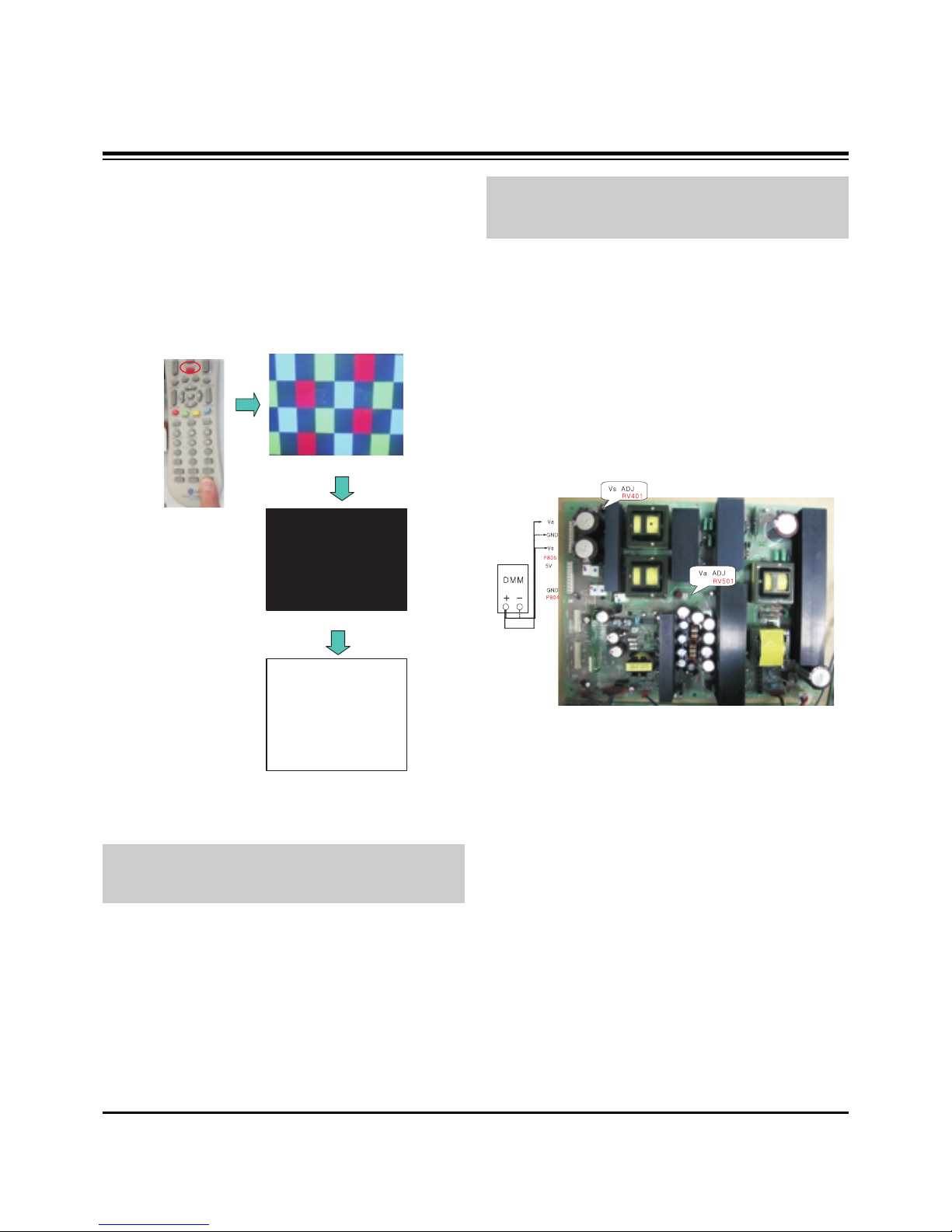
6-2. Setting of Device
6-3. EDID DATA for 60PY3DF
:EDID for HDMI-1 (DDC (Display Data Channel) Data)
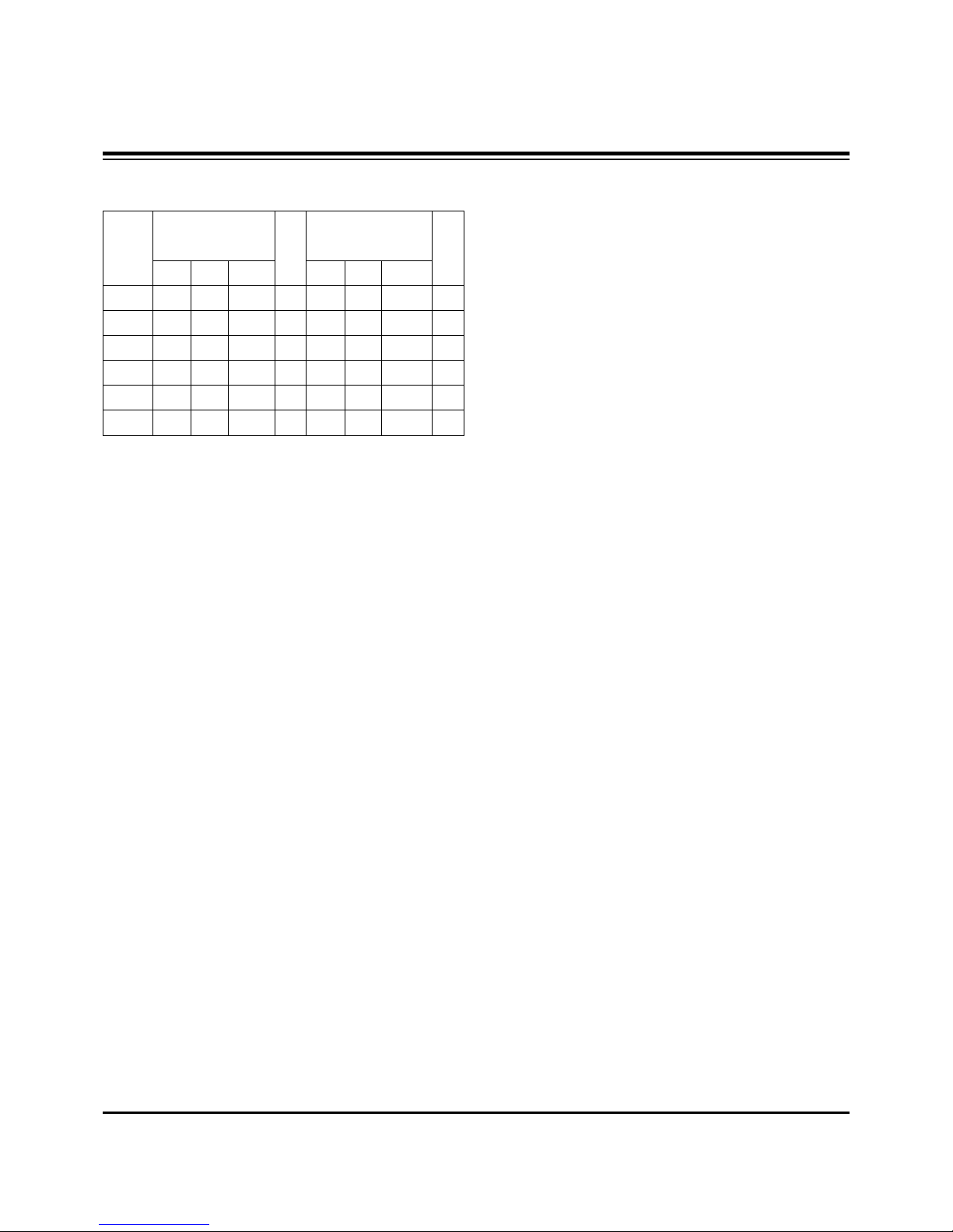
EDID table =
0 1 2 3 4 5 6 7 8 9 A B C D E F
_________________________________________________
0 | 00 FF FF FF FF FF FF 00 1E 6D 01 00 01 01 01 01
10 | 00 11 01 03 80 73 41 96 0A CF 74 A3 57 4C B0 23
20 | 09 48 4C AF CF 00 31 40 45 40 61 40 81 80 A9 40
30 | 01 01 01 01 01 01 66 21 50 B0 51 00 1B 30 40 70
40 | 36 00 C4 8E 21 00 00 1E 02 3A 80 18 71 38 2D 40
50 | 58 2C 45 00 C4 8E 21 00 00 1E 00 00 00 FD 00 30
60 | 58 1F 64 11 00 0A 20 20 20 20 20 20 00 00 00 FC
70 | 00 4C 47 20 54 56 0A 20 20 20 20 20 20 20 01 8A
0 1 2 3 4 5 6 7 8 9 A B C D E F
_________________________________________________
0 | 02 03 16 F1 47 84 05 03 02 20 22 10 23 15 07 50
10 | 65 03 0C 00 10 00 01 1D 00 72 51 D0 1E 20 6E 28
20 | 55 00 C4 8E 21 00 00 1E 01 1D 80 18 71 1C 16 20
30 | 58 2C 25 00 C4 8E 21 00 00 9E 8C 0A D0 8A 20 E0
40 | 2D 10 10 3E 96 00 C4 8E 21 00 00 18 8C 0A D0 8A
50 | 20 E0 2D 10 10 3E 96 00 13 8E 21 00 00 18 26 36
60 | 80 A0 70 38 1F 40 30 20 25 00 C4 8E 21 00 00 1A
70 | 00 00 00 00 00 00 00 00 00 00 00 00 00 00 00 10
:EDID for HDMI-2 (DDC (Display Data Channel) Data)
EDID table =
0 1 2 3 4 5 6 7 8 9 A B C D E F
_________________________________________________
0 | 00 FF FF FF FF FF FF 00 1E 6D 01 00 01 01 01 01
10 | 00 11 01 03 80 73 41 96 0A CF 74 A3 57 4C B0 23
20 | 09 48 4C AF CF 00 31 40 45 40 61 40 81 80 A9 40
30 | 01 01 01 01 01 01 66 21 50 B0 51 00 1B 30 40 70
40 | 36 00 C4 8E 21 00 00 1E 02 3A 80 18 71 38 2D 40
50 | 58 2C 45 00 C4 8E 21 00 00 1E 00 00 00 FD 00 30
60 | 58 1F 64 11 00 0A 20 20 20 20 20 20 00 00 00 FC
70 | 00 4C 47 20 54 56 0A 20 20 20 20 20 20 20 01 8A
0 1 2 3 4 5 6 7 8 9 A B C D E F
________________________________________________
0 | 02 03 16 F1 47 84 05 03 02 20 22 10 23 15 07 50
10 | 65 03 0C 00 20 00 01 1D 00 72 51 D0 1E 20 6E 28
20 | 55 00 C4 8E 21 00 00 1E 01 1D 80 18 71 1C 16 20
30 | 58 2C 25 00 C4 8E 21 00 00 9E 8C 0A D0 8A 20 E0
40 | 2D 10 10 3E 96 00 C4 8E 21 00 00 18 8C 0A D0 8A
50 | 20 E0 2D 10 10 3E 96 00 13 8E 21 00 00 18 26 36
60 | 80 A0 70 38 1F 40 30 20 25 00 C4 8E 21 00 00 1A
70 | 00 00 00 00 00 00 00 00 00 00 00 00 00 00 00 00
:EDID for HDMI-3 (DDC (Display Data Channel) Data)
EDID table =
0 1 2 3 4 5 6 7 8 9 A B C D E F
__________________________________________________
0 | 00 FF FF FF FF FF FF 00 1E 6D 01 00 01 01 01 01
10 | 00 11 01 03 80 73 41 96 0A CF 74 A3 57 4C B0 23
20 | 09 48 4C AF CF 00 31 40 45 40 61 40 81 80 A9 40
30 | 01 01 01 01 01 01 66 21 50 B0 51 00 1B 30 40 70
40 | 36 00 C4 8E 21 00 00 1E 02 3A 80 18 71 38 2D 40
50 | 58 2C 45 00 C4 8E 21 00 00 1E 00 00 00 FD 00 30
60 | 58 1F 64 11 00 0A 20 20 20 20 20 20 00 00 00 FC
70 | 00 4C 47 20 54 56 0A 20 20 20 20 20 20 20 01 8A
0 1 2 3 4 5 6 7 8 9 A B C D E F
_________________________________________________
0 | 02 03 16 F1 47 84 05 03 02 20 22 10 23 15 07 50
10 | 65 03 0C 00 30 00 01 1D 00 72 51 D0 1E 20 6E 28
20 | 55 00 C4 8E 21 00 00 1E 01 1D 80 18 71 1C 16 20
30 | 58 2C 25 00 C4 8E 21 00 00 9E 8C 0A D0 8A 20 E0
40 | 2D 10 10 3E 96 00 C4 8E 21 00 00 18 8C 0A D0 8A
50 | 20 E0 2D 10 10 3E 96 00 13 8E 21 00 00 18 26 36
60 | 80 A0 70 38 1F 40 30 20 25 00 C4 8E 21 00 00 1A
70 | 00 00 00 00 00 00 00 00 00 00 00 00 00 00 00 F0
:EDID DATA for RGB
EDID table =
0 1 2 3 4 5 6 7 8 9 A B C D E F
________________________________________________
0 | 00 FF FF FF FF FF FF 00 1E 6D 01 00 01 01 01 01
10 | 00 11 01 03 18 73 41 96 0A CF 74 A3 57 4C B0 23
20 | 09 48 4C AF CF 00 31 40 45 40 61 40 81 80 A9 40
30 | 01 01 01 01 01 01 66 21 50 B0 51 00 1B 30 40 70
40 | 36 00 C4 8E 21 00 00 1A 02 3A 80 18 71 38 2D 40
50 | 58 2C 45 00 C4 8E 21 00 00 1E 00 00 00 FD 00 30
60 | 58 1F 64 11 00 0A 20 20 20 20 20 20 00 00 00 FC
70 | 00 4C 47 20 54 56 0A 20 20 20 20 20 20 20 01 F6

- 9 -
ADJUSTMENT INSTRUCTIONS
0 1 2 3 4 5 6 7 8 9 A B C D E F
__________________________________________________
0 | 02 03 04 00 0E 1F 00 80 51 00 1E 30 40 80 37 00
10 | C4 8E 21 00 00 1C F1 27 00 A0 51 00 25 30 50 80
20 | 37 00 C4 8E 21 00 00 1C 26 36 80 A0 70 38 1F 40
30 | 30 20 25 00 C4 8E 21 00 00 0A 00 00 00 00 00 00
40 | 00 00 00 00 00 00 00 00 00 00 00 00 00 00 00 00
50 | 00 00 00 00 00 00 00 00 00 00 00 00 00 00 00 00
60 | 00 00 00 00 00 00 00 00 00 00 00 00 00 00 00 00
70 | 00 00 00 00 00 00 00 00 00 00 00 00 00 00 00 BC
7. Adjustment of White Balance
7-1. Required Test Equipment
(1) Color Analyzer : CA-210 (CH 9)
=> To adjust color temperature of LCD, CS-1000 is the
Color Analyzer(CA-210) and should be set to use CH 9
in which white, red, green, and blue color are corrected.
Conduct the adjustment according to the coordinates for
White Balance adjustment in the table below.
(2) Computer for adjusting (necessary for the automatic
adjustment, possible to communicate with the RS-232C,
Baud Rate : 115200)
(3) Video Signal Generator MSPG-925F 720p, 216Gray
(Model :217, Pattern 78)
7-2. Connection Diagram of Equipment
for Measuring (Automatic Adjustment)
Use the internal pattern to adjust White Balance. The pattern
is automatically given when the automatic adjustment device
is connected or when a user presses ADJ on the remote
controller to start Ez Adjust and then selects 6.White-Balance.
7-3. White Balance Adjustment Method
Basically it uses the internal pattern but when internal pattern
is not possible, you can select HDMI input for adjustment.
Through the option at the most bottom part of the Ez Adjust
Menu 7.White Balance menu, you can select NONE, INNER
and HDMI, and the default is set to INNER. When the
adjustment cannot be done with the internal pattern, you can
select HDMI input for adjustment.
For manual adjustment, press the ADJ KEY of the adjustment
R/C to enter Ez Adjust 7.White-Balance, and the pattern is
automatically displayed. (When you set the Option to INNER,
the default is always set to INNER)
(1) Connect the set according to the internal pattern or HDMI
input in accordance with measuring device connection
diagram.
(2) Set the Baud Rate of RS-232C to 115200. It is set to
115200 as default.
(3) Connect the RS-232C Cable to the set.
(4) Connect the HDMI Cable to the set. (Limited to the set with
HDMI option)
(5) Select and adjust the model applicable to PA73A chassis
from the adjuster.
7-4. Automatic Adjustment
(1) Execute POWER ON(Â) of the adjustment R/C to execute
automatic adjustment or set the Baud Rate to 115200.
(2) Always start adjustment with “wb 00 00”and end
adjustment with “wb 00 ff”(Adjust the offset if necessary)
(3) RS-232C command used for the automatic adjustment
Ex) Wb 00 00-----white balance Automatic Adjustment Start
Wb 00 10-----Gain Adjustment start (Internal pattern)
Ja 00 ff------Adjustment Data
Jb 00 c0
...
...
Wb 00 1f-----Gain Adjustment End
*(wb 00 20(Start), wb 00 2f(End))----- When adjust Off-set
Wb 00 ff------White Balance Automatic Adjustment End
(Disappear Inside pattern)
(internal pattern)
Connection Diagram for Internal Pattern
Connection Diagram for HDMI Input
wb
wb
wb
wb
wb
wb
00
00
00
00
00
00
00
10
1f
20
2f
ff
White Balance Adjustment Start
Gain Adjustment Start(Internal white pattern)
Gain Adjustment End
Offset Adjustment Start(Internal white pattern)
Offset Adjustment End
White Balance Adjustment End
(Disappear Internal pattern)
RS-232C COMMAND
[CMD ID DATA]
Meaning

- 10 -
ADJUSTMENT INSTRUCTIONS
(4) Adjustment Map
7-5. Manual Adjustment
(1) Required Test Equipment: CA-100
(2) Enter the ‘Ez - Adjust’by pressing the ADJ on the Service
R/C.
(3) Select 9.TEST PATTERN using the CH + / - KEY and
press the Enter KEY to execute a heat run for more than
30 minutes.
(4) Zero Calibrate of the Color Analyzer, then attach sensor to
PDP module surface when you adjust.
(5) Select ‘6. White-Balance’of ‘Ez - Adjust’by pressing the
ADJ KEY on the Service R/C. Then enter adjustment mode
by pressing the Right KEY (
G
) .
(The internal pattern of full white appears by pressing
G
)
(6) The adjustment is conducted in three levels of color
temperature; COOL, MEDIUM, and WARM.
1) For all color temperatures, fix R-Cut / G-Cut / B-Cut to
64.
2) Color Temperature: Cool, Medium, Warm
Adjust the High Light by using the G Gain / R Gain.
R, G, B Gain does not go over 192.
Full White 216gray
[Cool]
X; 0.276±0.002 Y; 0.283±0.002
Color temperature: 11000°K
dUV: -3dUV
[Medium]
X; 0.285±0.002 Y; 0.293±0.002
Color temperature: 9300°K
dUV: -3dUV
[Warm]
X; 0.313±0.002 Y; 0.329±0.002
Color temperature: 6500°K
dUV: -3dUV
R Gain
G Gain
B Gain
R Cut
G Cut
B Cut
Jg
Jh
Ji
Cool
Ja
Jb
Jc
Mid
RS-232C COMMAND
[CMD ID DATA]
CENTER
(DEFAULT)(Decimal)
Jd
Je
Jf
00
00
00
255
255
255
127
127
127
Warm
Min
Max
(Deci
mal)
184
189
192
64
64
64
Cool
192
184
161
64
64
64
Mid
192
150
84
64
64
64
Warm

- 11 -
BLOCK DIAGRAM

- 12 -
BLOCK DIAGRAM
ddc1
hpd1ddc
ddc2
ddc3
hpd2
hpd3
5v1
5v2
5v3
hdmi1
hdmi2
hdmi3
detect1
detect2
detect3
To cpu
mst3361
sel1
sel2
sel3
From
cpu
MST3361 + TMDS341AFPC , 3 port HDMI (HPD Control)
Hdmi_sig1
Hdmi_sig2
Hdmi_sig3
EDID1
HDCP
rom
EDID2
EDID1
Hdmi_sig
TMDS341
hpd1
hpd2
hpd3
Micom
CEC
CEC
CEC

- 13 -
BLOCK DIAGRAM
ATI
(X260)
I2C Master
AT/NT Tuner
0xC2
HDMI
ADC
(MST3361)
0X9C
Temp.
Sensor
(LM75)
0X94
U-Com
(MTV416)
0x50
I2C_CH1 (+3.3V_L & +5V_L)
I2C_CH2 (+3.3V_L & +5V_L)
I2C_CH3 (+3.3V_L)
Port
Expander
(M62320)
0X74
Audio
Switch
(TEA6420)
0X9A
DASP
(NTP3000)
0X54
PDP Module
0x1C
VSB/QAM
(LGDT3703)
Main
0X1C
Live Dead
CS8416A
0X20(W)
0X21(R)
EEPROM
(24LC512)
0xA6
CH1
CH2
CH3
FRC94XYH
0x94
EEPROM
(24LC16)
5V
5V 5V
2.5V
IIC channel map

- 14 -
BLOCK DIAGRAM
+12.0V
+12.0V
+6.0V
+6.0V
CS4344
CS4344 CS5340
CS5340
PQ05DZ1U
PQ05DZ1U
KIA78R09
KIA78R09 FAN1
FAN1 KIA78R09
KIA78R09 FAN2, 3
FAN2, 3
MC33078
MC33078
X260
X260
HYB18T512(4EA)
HYB18T512(4EA)
AZ1117H-1.8
AZ1117H-1.8 LM75
LM75
ICL3232CBNZ
ICL3232CBNZ
+5.0VST
+5.0VST
+3.3V_L
+3.3V_L
AT/NT Tuner
AT/NT Tuner
+5V_L
+5.0V
SI3865
SI3865
PQ05DZ1U
PQ05DZ1U
Live Power
Dead Power
Live-on
AZ1117H-3.3
AZ1117H-3.3 LGDT3703(MAIN)
LGDT3703(MAIN)
SC1565-1.8
SC1565-1.8 ISL6549CB
ISL6549CB
1.2V
1.8V
ISL6549CB
ISL6549CB 1.8V
MK3727D
MK3727D 74LVT16373(2EA)
74LVT16373(2EA) S29GL256
S29GL256
THC63LVD1023
THC63LVD1023
+3.3V_L
HYB18T512(4EA)
HYB18T512(4EA) MK3727D
MK3727D
+19.0V
+19.0V NTP3000
NTP3000
NTP3000
NTP3000
1.8V
BA033FP-3.3
BA033FP-3.3 MTV416
MTV416
AZ1086-1.8
AZ1086-1.8
AZ1117H-3.3
AZ1117H-3.3
SC1565-2.5
SC1565-2.5
MST3369
MST3369
9.0V
TEA6420
TEA6420
9.0V
CS8416
CS8416
KIA78R09
KIA78R09
MK3727D
MK3727D
MIC2505
MIC2505
3.3VST_MICOM
24C08
24C08
FRC94XYH
FRC94XYH
Live-on
24C512
24C512
STMAV335
STMAV335
ISP1504
ISP1504
MIC2505
MIC2505
KIA7805
KIA7805
AZ1085S-3.3
AZ1085S-3.3
AZ1085S-1.8
AZ1085S-1.8 24C16
24C16
FRC
FRC
SC1565-2.6
SC1565-2.6 MIC3910-2.5
MIC3910-2.5
SC1592-1.0
SC1592-1.0
12.0V
HY5DU281622
HY5DU281622
SC2595-1.0
SC2595-1.0
Power Block

- 15 -
NOTES

- 16 -
EXPLODED VIEW
400
240
102
101
103
602
600
303
304
306
307
121
300
302
301
305
120
603
601
580
581
582
260
250
208 201
202
203
204
204
200
205
206
209
207
205 206 207
560
570
540
542
541
502
520
501
590
A21
A2
901
900

- 17 -
EXPLODED VIEW PARTS LIST
101 EAL30846301 Fan Module,G6015S12b2 1.8KRPM DC 12V 840MA 12W 60HZ 200MM3
102 MJH32511701 Supporter,PRESS EGI 0.6 NON EGI FAN_SUPP
103 AJJ31606802 Supporter Assembly,60PY30, SKD, FAN SUPPORTER ASSY
AJJ31606801 Supporter Assembly,60PY30, FAN SUPPORTER ASSY
120 EAB33735401 Speaker Assembly,50PY3 SLIM SPEAKER ASSY RIGHT
121 EAB33735402 Speaker Assembly,50PY3 SLIM SPEAKER LEFT ASSY
200 EAJ32791801 PDP,Module-FullHD PDP60H10000.ADLGB FULLHD 60INCH 1920X1080 16/9 PDP DIVISION
EAJ32791701 PDP,Module-FullHD PDP60H10000.AKLGG FULLHD 60INCH
201 EBR32922301 PCB Assembly,EBR32922301 CTRL ASS’Y 60 H1 Full-HD CTRL PDP DIVISION
202 EBR32015901 PCB Assembly,EBR32015901 YDRV ASS’Y 60 H1 Full-HD YDRV TOP PDP DIVISION
203 EBR32016101 PCB Assembly,EBR32016101 YDRV ASS’Y 60 H1 Full-HD YDRV BOTTOM PDP DIVISION
204 EBR32003901 PCB Assembly,EBR32003901 XRLB ASSY 60 H1 Full-HD XLB & XRT PDP DIVISION
205 EBR32004501 PCB Assembly,EBR32004501 XRCLBT ASSY’ 60 H1 Full-HD XCLB & XCRT PDP DIVISION
206 EBR32004601 PCB Assembly,EBR32004601 XRCRBT ASSY’ 60 H1 Full-HD XCRB & XCLT PDP DIVISION
207 EBR32004701 PCB Assembly,EBR32004701 XRRB ASSY 60 H1 Full-HD XRB & XLT PDP DIVISION
208 EBR32324201 PCB Assembly,EBR32324201 YSUS ASS’Y 60 H1 Full HD PDP DIVISION
209 EBR32324301 PCB Assembly,EBR32324301 ZSUS ASS’Y 60 H1 Full HD PDP DIVISION
240 AJJ30996203 Supporter Assembly,60PY30, SKD, Vertical Supporter Right Assy.
AJJ30996201 Supporter Assembly,60PY30, Vertical Supporter Right Assy
250 AJJ30996204 Supporter Assembly,60PY30, SKD, Vertical Supporter Left Assy.
AJJ30996202 Supporter Assembly,60PY30, Vertical Supporter Left Assy.
260 AJJ31606903 Supporter Assembly,60PY30, MODULE SUPP_SIDE HOR.+ SUPP_SIDE. PANTON ASSY
AJJ31606902 Supporter Assembly,60PY30, MODULE SUPP_SIDE HOR.+ SUPP_SIDE, Press
300 ABJ30995004 Cabinet Assembly,60PY3DR-UA PA71A 60 LG, C/SKD
ABJ30995002 Cabinet Assembly,60PY3DR-UA PA71A 60 LG
301 ADV31660202 Frame Assembly,60py30 mf-056l 60 frame assy, LG
302 MBH32314201 Cabinet,MOLD ABS 60PY30 ABS E3, Cabinet, XCANVAS
303 AJJ30996402 Supporter Assembly,60PY30, Filter Supporter Top, SKD
AJJ30996401 Supporter Assembly,60PY30, Filter Supporter Top
304 AJJ30996502 Supporter Assembly,60PY30, Filter Supporter Bottom Assy C/SKD
AJJ30996501 Supporter Assembly,60PY30, Filter Supporter Bottom Assy
305 5230V00018B Filter,CUTTING ACRYL TOP 60PY2DR ø‹ 60inch PDP MITSUI 60 GLASS FILTER
306 AJJ30996603 Supporter Assembly,60PY30, SKD, Filter Supporter Right Assy
AJJ30996601 Supporter Assembly,60PY30, Filter Supporter Right Assy
307 AJJ30996703 Supporter Assembly,60PY3, SKD, Filter Supporter Left Assy
AJJ30996701 Supporter Assembly,60PY30, Filter Supporter Left Assy
400 ACQ30995608 Cover Assembly,Rear 60PY3DF-ZA PD75A 60 Back Cover Assy, SKD, Without DVR & Without Woofer
ACQ30995604 Cover Assembly,Rear 60PY3D PA71A 60 Back Cover Assy, Without DVR & Without Woofer
501 AGU31681105 Plate Assembly,PLATE TUNER BOT SMALL, 60PY3DF-UA(E3)
502 AGU31680911 Plate Assembly,PLATE TUNER COVER SMALL, 60PY3 E3 /AMERICA
520 EBR36117301 PCB Assembly,Main PA73A 60PY3DF-UA AUSLLHX 60PY3DF-UA MAIN MANUAL ASSY
540 EAJ33837501 VFD,16SL02HS1 237
541 ABA32560202 Bracket Assembly,BRACKET 60PY3DF-ZA PD75A VFD BRACKET ASSY, CSKD
ABA32560201 Bracket Assembly,BRACKET 60PY3DF-ZA PD75A VFD BRACKET ASSY
542 EBT34918701 Chassis Assembly,SUB PA71A 60PY3DR VFD ASSY.
560 EBR36865501 PCB Assembly,Audio BUZZER ASSEMBLY SOUND S.T PDP 50PB3,60PY3 PDP BUZZER B/D YANG WOO CO
570 EBR33918301 PCB Assembly,SUB M.I PA71A 50PB3DR KOREA 50PB3DR PRE AMP
580 EAY32929201 SMPS,AC/DC 1H391W 100VTO240V 800W 50 TO 60HZ UL/CE/TUV 60INCH PDP FULL HD
581 EAY32929401 SMPS,AC/DC 1H391W-PFC 100VTO240V 800W 50 TO 60HZ UL/CE/TUV 60INCH PDP FULL HD
582 EAY32929901 SMPS,AC/DC 1H391W-ACIN 100VTO240V 800W 50 TO 60HZ UL/CE/TUV 60INCH PDP FULL HD
590 EAM35012702 Filter,AC Line IF2-N10CEWL1 1.1mH 250VAC 10A 0.22uF 1000pF
600 EBT36207701 Chassis Assembly,SUB PA73A SUB PA73A 60PY3DF-UB SIDE AV ASSY
601 EBR35103101 PCB Assembly,SUB M.I PA71A SIDE A/V
602 ABA30998703 Bracket Assembly,AV PY30 AB E3_SIDE AV BRACKET ASSY, USA,With USB
603 MGJ32323501 Plate,Shield PRESS AL 1.0 SHIELD AL E3 PY30 SHIELD,SIDE AV
900 AAN30997003 Base Assembly,STAND 60PY3 PA64F Stand Assy, SKD
AAN30997001 Base Assembly,STAND 60PY30 PA64F Stand Assy,
901 MCK32693801 Cover,MOLD ABS 60PY3 ABS COVER CABLE
A2 6710900011Z Remote Controller,COMPLEX LA73A 42LB5DF-UA USA_Full HD_NON DVR
A21 3550V00684B Cover,BATTERY BACK ABS, HF-380 BK
No. Part No. Description

- 18 -
REPLACEMENT PARTS LIST
LOCA. NO PART NO DESCRIPTION
Q300
Q301
Q302
Q303
Q304
Q305
Q306
Q307
Q308
Q309
Q310
Q311
Q312
Q313
Q314
Q315
Q316
Q317
Q318
Q319
Q400
Q401
Q402
Q403
Q404
Q405
Q406
Q407
Q409
Q410
Q411
Q500
Q501
Q503
Q504
Q505
Q506
Q508
Q510
Q511
Q512
Q513
Q514
Q515
Q516
Q601
EBK32756101
EBK32756101
0TR387500AA
0TR387500AA
0TR387500AA
0TR387500AA
0TR387500AA
0TR387500AA
0TR387500AA
0TR387500AA
0TR387500AA
0TR387500AA
0TR387500AA
0TR387500AA
0TR387500AA
EBK32756101
0TFDI80001B
0TFDI80001B
0TFDI80001B
0TFDI80001B
0TR387500AA
0TR104009AF
0TR104009AF
0TR387500AA
0TR387500AA
0TR104009AF
0TR104009AF
0TFDI80001B
0TR104009AF
0TR104009AF
0TR387500AA
0TR387500AA
0TR387500AA
0TFDI80001B
0TFDI80001B
0TR387500AA
0TR387500AA
0TR150400BA
0TR150400BA
0TR387500AA
0TR387500AA
0TR102009AM
0TFDI80001B
0TFDI80001B
0TFDI80001B
0TR150400BA
FET,Si4800BDY N-CHANNEL M
2SC3875S(ALY) NPN 5V
FET,Si4800BDY N-CHANNEL M
FET,2N7002(F) N-CHANNEL D
2SC3875S(ALY) NPN 5V
KRC104S NPN 40V
KRC104S NPN 40V
2SC3875S(ALY) NPN 5V
KRC104S NPN 40V
KRC104S NPN 40V
FET,2N7002(F) N-CHANNEL D
KRC104S NPN 40V
KRC104S NPN 40V
2SC3875S(ALY) NPN 5V
FET,2N7002(F) N-CHANNEL D
2SC3875S(ALY) NPN 5V
2SA1504S(ASY) PNP -5V
2SC3875S(ALY) NPN 5V
KRA102S PNP -30V 0V -
FET,2N7002(F) N-CHANNEL D
2SA1504S(ASY) PNP -5V
LOCA. NO PART NO DESCRIPTION
IC101
IC200
IC201
IC202
IC203
IC206
IC207
IC208
IC300
IC301
IC302
IC303
IC304
IC305
IC306
IC307
IC308
IC310
IC400
IC401
IC402
IC403
IC404
IC405
IC406
IC407
IC408
IC409
IC501
IC505
IC507
IC508
IC600
IC601
IC602
IC603
IC604
IC605
IC605
IC700
IC704
IC705
IC707
IC708
IC711
IC712
EAN32808701
EAN33624401
EAN33931901
EAN33931901
EAN33624401
EAN33624401
0IMCRAL021A
EAN33624401
0IKE702900G
0IMCRSJ001B
0IPMG00049A
0IPMG00049A
EAN33573001
0ISTLPH026A
0IPRP00009A
0IKE702900G
0IPMGA0010A
0IMCRAL006A
0IMCRSJ001B
0IPMGA0010A
0IPRP00696C
EAN32724701
0IMMRCS012B
0IMMRAL014D
0IMMRAL014D
0IMMRAL014D
0IMMRAL014D
EAN35942401
0IPRPCI017A
EAN32404601
0IPMG00049A
0IMCRMN028C
0IPMGKE030A
EAN32174001
0IPMGSH019A
0IPMGA0010A
0ICTMLG019A
0IPMG00049A
0IPMGSH019A
EAN32662801
0IPMGKE030A
0IMI623200B
0IPMGKE032A
0IPMGKE032A
0IPMGKE030A
EAN32013101
XILLEON260 500MVTO2.1V,35
HYB18TC512160BF-3S 512MBI
TC74LCX16373AFT 2V~3.6V 5
HYB18TC512160BF-3S 512MBI
AT24C512W-10SU-2.7 512KBI
HYB18TC512160BF-3S 512MBI
KIA7029AF - 3TO15V 2.9V
SC1565IST-2.5TR 2.2TO5V 2
AZ1117H-1.8TR/E1[H13A] 3.
SC2621ASTRT 18V 5V~17.4
74LVC14APW 1.2TO3.6V 01
ICL3232CBNZ 3VTO5.5V - SS
KIA7029AF - 3TO15V 2.9V
AZ1117H-3.3 4.75TO10V 3.3
AT24C16AN-10SU-2.7 16KBIT
SC1565IST-2.5TR 2.2TO5V 2
AZ1117H-3.3 4.75TO10V 3.3
MST3361M-LF-170 3.3V_2.5V
STMAV335 4.0TO5.5V 5NSEC
CAT24WC08W-T(MST3000) 8KB
AT24C02BN-10SU-1.8 2KBIT
TMDS341APFCR 3TO3.6V 10NS
CS8416-CZZR 3.13VTO3.46V,
NTP3000 7TO30V 5.5V 01%
AZ1117H-1.8TR/E1[H13A] 3.
MSP4450K-QA-D6 7.6TO8.7V_
KIA78R05F 6TO12V 5V 8W DP
THC63LVD1023 3.0VTO3.6V 1
PQ018EZ02ZPH(PB-FREE) 2.3
AZ1117H-3.3 4.75TO10V 3.3
LGDT3303 3TO5 25m 16M TQF
AZ1117H-1.8TR/E1[H13A] 3.
PQ018EZ02ZPH(PB-FREE) 2.3
KA7809ERTM 35V to 40V 9V
KIA78R05F 6TO12V 5V 8W DP
M62320FP(SOP) 4.5TO5.5V 0
KIA78R09F 10TO25V 9V 8W D
KIA78R05F 6TO12V 5V 8W DP
MIC2505-2YM 2.7V TO 7.5V
IC
RUN DATE : 2007.5.3
TRANSISTOR

- 19 -
LOCA. NO PART NO DESCRIPTION
Q602
Q602
Q603
Q603
Q611
Q702
D300
D301
D302
D303
D304
D402
D404
D408
ZD405
ZD406
ZD407
ZD408
ZD409
ZD415
ZD416
ZD417
ZD418
ZD419
ZD420
ZD421
ZD501
ZD502
ZD700
ZD705
ZD710
ZD711
ZD712
C1
C1
C2
C200
C201
C202
C203
C204
C205
C206
C207
C208
C209
C210
0TFDI80001B
0TFDI80001B
0TFDI80001B
0TFDI80001B
0TR387500AA
0TFVI80067A
0DSGD00038A
0DRSE00038A
0DRSE00038A
0DD184009AA
0DD184009AA
0DD184009AA
0DD184009AA
0DD184009AA
0DZ360009EB
0DZ360009EB
0DZ560009DA
0DZ560009DA
0DZ560009DA
0DZ360009EB
0DZ560009DA
0DZ560009DA
0DZ560009DA
0DZ560009DA
EAH33945901
EAH33945901
0DZ560009DA
0DZRM00248A
0DZ360009EB
0DZ360009EB
0DZ560009DA
0DZ360009EB
0DZ360009EB
0CE477DD618
0CE4763F618
0CH3104K566
0CK104BF56A
EAE33970001
0CK104BF56A
0CK104BF56A
0CK104BF56A
EAE33970001
0CK104BF56A
EAE33970001
0CK104BF56A
0CK104BF56A
0CK104BF56A
FET,2N7002(F) N-CHANNEL D
2SC3875S(ALY) NPN 5V
FET,SI3865BDV(E3) N-CHANN
1N4148W 1.25V 100V 150MA 2A
SDC15 1.3V 14.3VTO16.4V 21.
KDS184 KDS184 TP KEC - 85V
Zener,UDZS3.6B 3.6V 3.6TO3.845V 1
Zener,UDZS5.6B 5.6V 5.49TO5.73V 6
Zener,UDZS3.6B 3.6V 3.6TO3.845V 1
Zener,UDZS5.6B 5.6V 5.49TO5.73V 6
CDS3C30GTH 3V 120V 1.9
Zener,UDZS5.6B 5.6V 5.49TO5.73V 6
Zener,RLZ8.2B 8.2V 7.78TO8.19V 8O
Zener,UDZS3.6B 3.6V 3.6TO3.845V 1
Zener,UDZS5.6B 5.6V 5.49TO5.73V 6
Zener,UDZS3.6B 3.6V 3.6TO3.845V 1
EGR477M010T6G1G11G 470uF 20%
ESF476M016T1A5E05G 47uF 20% 1
0805B104K500CT 100nF 10% 50V
C1005X7R104KET 100nF 10% 16V
CS1005X5R105K6R3NR 1uF 10% 6.
C1005X7R104KET 100nF 10% 16V
CS1005X5R105K6R3NR 1uF 10% 6.
C1005X7R104KET 100nF 10% 16V
CS1005X5R105K6R3NR 1uF 10% 6.
C1005X7R104KET 100nF 10% 16V
LOCA. NO PART NO DESCRIPTION
C211
C2114
C2115
C2116
C2117
C2119
C212
C2120
C2122
C2124
C2126
C2127
C2127
C2128
C213
C2130
C2131
C2132
C2133
C2134
C2136
C2137
C2138
C2139
C214
C2140
C2141
C2142
C2143
C2144
C2145
C2146
C2147
C2148
C2149
C215
C2150
C2151
C2152
C2153
C2154
C2155
C2156
C2157
C2158
C2159
C216
C2160
C2161
C2162
C2163
EAE33970001
0CK104BF56A
0CK104BF56A
0CK104BF56A
0CK104BF56A
0CK104BF56A
0CK104BF56A
0CK104BF56A
0CK104BF56A
0CK106EF56A
0CC150BK4AA
0CC150BK4AA
0CZZB00035A
0CK102BK56A
0CK104BF56A
0CK104BF56A
0CK106EF56A
0CK104BF56A
0CK106EF56A
0CK104BF56A
0CK106EF56A
0CK104BF56A
0CK104BF56A
0CK104BF56A
EAE33970001
0CK104BF56A
0CK104BF56A
0CK104BF56A
0CK104BF56A
0CE107WF6DC
0CK105CD56A
0CK104BF56A
0CK104BF56A
0CK104BF56A
0CK104BF56A
0CK104BF56A
0CK104BF56A
0CK104BF56A
0CE226WF6DC
EAE30840301
EAE33970001
EAE33970001
EAE33970001
EAE33970001
EAE33970001
EAE33970001
0CK104BF56A
EAE33970001
0CK104BF56A
0CK104BF56A
0CK104BF56A
CS1005X5R105K6R3NR 1uF 10% 6.
C1005X7R104KET 100nF 10% 16V
C3216X7R1C106KT 10uF 10% 16V
C1005C0G1H150JT 15pF 5% 50V C
GRM1555C1H330J 33pF 5% 50V C0
0402B102K500CT 1nF 10% 50V X7
C1005X7R104KET 100nF 10% 16V
C3216X7R1C106KT 10uF 10% 16V
C1005X7R104KET 100nF 10% 16V
C3216X7R1C106KT 10uF 10% 16V
C1005X7R104KET 100nF 10% 16V
C3216X7R1C106KT 10uF 10% 16V
C1005X7R104KET 100nF 10% 16V
CS1005X5R105K6R3NR 1uF 10% 6.
C1005X7R104KET 100nF 10% 16V
MVK6.3TP16VC100M 100uF 20% 16
C1608X7R1A105KT 1uF 10% 10V X
C1005X7R104KET 100nF 10% 16V
MVK5.0TP16VC22M 22uF 20% 16V
10SVPC68M 68uF 20% 10V 1.97A
CS1005X5R105K6R3NR 1uF 10% 6.
C1005X7R104KET 100nF 10% 16V
CS1005X5R105K6R3NR 1uF 10% 6.
C1005X7R104KET 100nF 10% 16V
REPLACEMENT PARTS LIST
DIODE
CAPACITOR

- 20 -
LOCA. NO PART NO DESCRIPTION
C2164
C2165
C2166
C2167
C2168
C2169
C217
C2170
C2171
C2172
C2173
C2174
C2175
C2176
C2177
C2178
C2179
C218
C2180
C2181
C2182
C2183
C2184
C2185
C2186
C2187
C2188
C2189
C2189
C219
C2190
C2191
C2192
C2193
C2194
C2195
C2196
C2197
C2198
C2199
C220
C2200
C2201
C2202
C2203
C2204
C2205
C2206
C2207
C2208
C2209
0CK104BF56A
0CK104BF56A
0CK104BF56A
0CK104BF56A
0CK104BF56A
0CK104BF56A
0CK104BF56A
0CK104BF56A
0CK104BF56A
0CK104BF56A
0CE226WF6DC
EAE30840301
EAE33970001
EAE33970001
EAE33970001
EAE33970001
EAE33970001
EAE33970001
0CK104BF56A
0CK104BF56A
0CK104BF56A
0CK104BF56A
0CK104BF56A
0CK104BF56A
0CK104BF56A
0CK104BF56A
0CE226WF6DC
0CE107WF6DC
0CE107WF6DC
EAE30840301
0CK105CD56A
0CK105CD56A
0CK105CD56A
0CK105CD56A
0CK104BF56A
0CK104BF56A
0CK104BF56A
0CK104BF56A
0CK104BF56A
0CK105CD56A
EAE33970001
0CK105CD56A
0CK104BF56A
0CK104BF56A
0CK104BF56A
0CK104BF56A
EAE33970001
0CK104BF56A
0CK104BF56A
0CK104BF56A
0CK104BF56A
C1005X7R104KET 100nF 10% 16V
MVK5.0TP16VC22M 22uF 20% 16V
10SVPC68M 68uF 20% 10V 1.97A
CS1005X5R105K6R3NR 1uF 10% 6.
C1005X7R104KET 100nF 10% 16V
MVK5.0TP16VC22M 22uF 20% 16V
MVK6.3TP16VC100M 100uF 20% 16
10SVPC68M 68uF 20% 10V 1.97A
C1608X7R1A105KT 1uF 10% 10V X
C1005X7R104KET 100nF 10% 16V
C1608X7R1A105KT 1uF 10% 10V X
CS1005X5R105K6R3NR 1uF 10% 6.
C1608X7R1A105KT 1uF 10% 10V X
C1005X7R104KET 100nF 10% 16V
CS1005X5R105K6R3NR 1uF 10% 6.
C1005X7R104KET 100nF 10% 16V
LOCA. NO PART NO DESCRIPTION
C221
C2210
C2211
C2212
C2213
C2214
C2215
C2216
C2217
C2218
C2219
C222
C2220
C2221
C2222
C2223
C2224
C2225
C2226
C2227
C2228
C2229
C223
C2230
C2231
C2232
C2233
C2234
C2239
C224
C2240
C2241
C2242
C2243
C2244
C225
C226
C227
C228
C229
C230
C231
C232
C233
C234
C235
C236
C238
C239
C240
C241
0CK104BF56A
0CK104BF56A
0CK104BF56A
0CK104BF56A
0CK104BF56A
0CK104BF56A
0CK104BF56A
0CK104BF56A
0CK104BF56A
0CK104BF56A
0CK104BF56A
0CK104BF56A
0CK104BF56A
0CK104BF56A
0CK104BF56A
0CK104BF56A
0CK104BF56A
0CK104BF56A
0CK104BF56A
0CK104BF56A
0CK106EF56A
0CK104BF56A
0CK104BF56A
0CK104BF56A
0CK104BF56A
0CK104BF56A
0CK104BF56A
EAE30840301
0CK104BF56A
EAE33970001
0CK104BF56A
0CK104BF56A
0CK104BF56A
0CK104BF56A
0CK104BF56A
0CK104BF56A
0CK104BF56A
0CK104BF56A
0CK104BF56A
EAE33970001
EAE33970001
0CK104BF56A
0CK104BF56A
0CK104BF56A
EAE33970001
EAE33970001
0CK104BF56A
0CK104BF56A
0CK104BF56A
EAE30840301
0CK104BF56A
C1005X7R104KET 100nF 10% 16V
C3216X7R1C106KT 10uF 10% 16V
C1005X7R104KET 100nF 10% 16V
10SVPC68M 68uF 20% 10V 1.97A
C1005X7R104KET 100nF 10% 16V
CS1005X5R105K6R3NR 1uF 10% 6.
C1005X7R104KET 100nF 10% 16V
CS1005X5R105K6R3NR 1uF 10% 6.
C1005X7R104KET 100nF 10% 16V
CS1005X5R105K6R3NR 1uF 10% 6.
C1005X7R104KET 100nF 10% 16V
10SVPC68M 68uF 20% 10V 1.97A
C1005X7R104KET 100nF 10% 16V
REPLACEMENT PARTS LIST
Other manuals for 60PY3D - - 60" Plasma TV
2
This manual suits for next models
1
Table of contents
Other LG Plasma TV manuals
Popular Plasma TV manuals by other brands

Panasonic
Panasonic TH42PV500EY operating instructions

Insignia
Insignia NS-51P680A12 Guide d'installation rapide

VESTEL
VESTEL 17MB15E-5 Service manual

Panasonic
Panasonic Viera TX-P42XT50Y operating instructions

Samsung
Samsung PN60E550 Product highlights

Panasonic
Panasonic TXP42VT20E operating instructions