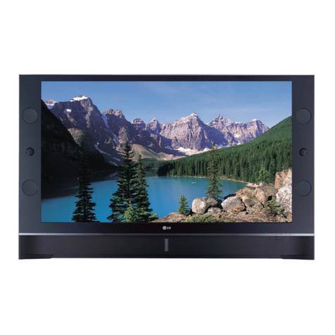
LG 56DC1D User manual

DLP Projection TV
SERVICE MANUAL
CAUTION
BEFORE SERVICING THE CHASSIS,
READ THE SAFETY PRECAUTIONS IN THIS MANUAL.
CHASSIS : MD-61A
MODEL : 56DC1D
MODEL : 56DC1D-AB
website:http://biz.LGservice.com
e-mail:http://www.LGEservice.com/techsup.html

- 2 -
CONTENTS
CONTENTS ................................................................................................................... 2
SAFETY PRECAUTIONS ..............................................................................................3
CONTROL DESCRIPTIONS ..........................................................................................4
SPECIFICATIONS .........................................................................................................7
ADJUSTMENT INSTRUCTIONS ..................................................................................11
PRINTED CIRCUIT BOARD.........................................................................................20
BLOCK DIAGRAM .......................................................................................................28
EXPLODED VIEW .......................................................................................................32
EXPLODED VIEW PARTS LIST...................................................................................33
REPLACEMENT PARTS LIST ....................................................................................34
SVC. SHEET ....................................................................................................................

- 3 -
SAFETY PRECAUTIONS
Many electrical and mechanical parts in this chassis have special safety-related characteristics. These parts are identified by in the
Schematic Diagram and Replacement Parts List.
It is essential that these special safety parts should be replaced with the same components as recommended in this manual to prevent
X-RADIATION, Shock, Fire, or other Hazards.
Do not modify the original design without permission of manufacturer.
General Guidance
An isolation Transformer should always be used during the
servicing of a receiver whose chassis is not isolated from the AC
power line. Use a transformer of adequate power rating as this
protects the technician from accidents resulting in personal injury
from electrical shocks.
It will also protect the receiver and it's components from being
damaged by accidental shorts of the circuitry that may be
inadvertently introduced during the service operation.
If any fuse (or Fusible Resistor) in this TV receiver is blown,
replace it with the specified.
When replacing a high wattage resistor (Oxide Metal Film Resistor,
over 1W), keep the resistor 10mm away from PCB.
Keep wires away from high voltage or high temperature parts.
Due to high vacuum and large surface area of picture tube,
extreme care should be used in handling the Picture Tube. Do
not lift the Picture tube by it's Neck.
Before returning the receiver to the customer,
always perform an AC leakage current check on the exposed
metallic parts of the cabinet, such as antennas, terminals, etc., to
be sure the set is safe to operate without damage of electrical
shock.
Leakage Current Cold Check(Antenna Cold Check)
With the instrument AC plug removed from AC source, connect an
electrical jumper across the two AC plug prongs. Place the AC
switch in the on position, connect one lead of ohm-meter to the AC
plug prongs tied together and touch other ohm-meter lead in turn to
each exposed metallic parts such as antenna terminals, phone
jacks, etc.
If the exposed metallic part has a return path to the chassis, the
measured resistance should be between 1MΩand 5.2MΩ.
When the exposed metal has no return path to the chassis the
reading must be infinite.
An other abnormality exists that must be corrected before the
receiver is returned to the customer.
Leakage Current Hot Check (See below Figure)
Plug the AC cord directly into the AC outlet.
Do not use a line Isolation Transformer during this check.
Connect 1.5K/10watt resistor in parallel with a 0.15uF capacitor
between a known good earth ground (Water Pipe, Conduit, etc.)
and the exposed metallic parts.
Measure the AC voltage across the resistor using AC voltmeter
with 1000 ohms/volt or more sensitivity.
Reverse plug the AC cord into the AC outlet and repeat AC voltage
measurements for each exposed metallic part. Any voltage
measured must not exceed 0.75 volt RMS which is corresponds to
0.5mA.
In case any measurement is out of the limits specified, there is
possibility of shock hazard and the set must be checked and
repaired before it is returned to the customer.
Leakage Current Hot Check circuit
1.5 Kohm/10W
To Instrument’s
exposed
METALLIC PARTS
Good Earth Ground
such as WATER PIPE,
CONDUIT etc.
AC Volt-meter
IMPORTANT SAFETY NOTICE
0.15uF

- 4 -
DESCRIPTION OF CONTROLS
- When using the remote control aim it at the remote control sensor of the set.
- There maybe a defect in operation of this remote control in an excessively bright room when viewing this set.
OK
TVD/A
INPUT
DVD
ARC
EXIT
VOL
TEXT
UPDATE
INDEX
Q.VIEW
MUTE
PR
FAV
LIST
I/II
MENU
SLEEP
GUIDE
MULTI
INFO
VCR
POWER
123
456
789
0
SSMPSM
HOLD
SIZE
MIX
TIME
REVEAL
APM
?
MODE
selects another device.
POWER
switches the set on from standby or off to
standby.
INFO
displays information on top of the screen
whilst watching the TV.
(In Digital mode only)
COLOURED BUTTONS
These buttons are used for teletext (only
TELETEXT models) or programme edit.
VCR BUTTONS
controls a video cassette recorder.
MULTI (MULTIMEDIA)
selects the Component, RGB or HDMI
modes.
switches the set on from standby.
OK
accepts your selection or displays the
current mode.
DD/ EEor FF/ GG
adjusts menu settings.
selects menu item.
Q.VIEW
returns to the previously viewed
programme.
NUMBER buttons
switches the set on from standby.
SSM
to select the sound appropriate to your
viewing programme character.
I/II
selects the sound output or the audio
mode.
APM (Adaptive Picture Mode)
Concurrently, compare with the
Dynamic
,
Standard
,
Mild
and
User
on the screen.
FAV (FAVOURITE)
selects a favourite programme.
D/A
selects analogue or digital mode.
switches the set on from standby.
INPUT
selects the TV, AV, Component, RGB or
HDMI modes.
switches the set on from standby.
ARC
changes the picture format.
GUIDE
shows a programme schedule.
(In Digital mode only)
EXIT
clears all on-screen displays and returns to
TV viewing from any menu.
MENU
displays on screen menus one by one.
exits the current menu.
memorizes menu changes.
TEXT
These buttons are used for teletext.
For further details, see the ‘Teletext’ section.
selects Subtitle on or off in
Digital
mode.
SLEEP
sets the sleep timer.
Brightness adjustment
adjusts screen brightness.
It returns to the default settings brightness
by changing mode source.
MUTE
switches the sound on or off.
LIST
displays the programme table.
PSM
adjusts the factory preset picture according
to the room.
VOL +/- (Volume Up/Down)
increases/decreases sound level.
PR +/- (Programme Up/Down)
selects a programme.
switches the set on from standby.

- 5 -
- Shown is a simplified representation of the set.
- What is shown here may be somewhat different from your set.
INPUT VOL PR
MENU OK
INPUT Button
FF/ GG
(Volume
Down/Up)
DD/ EE
(Programme Up/Down)
Operation Indicator/
Lamp Indicator/
Temperature Indicator
POWER Button
MENU Button
- Lamp indicator, operation indicator, and temperature indicator located below the front panel controls, reveal the
operating status of the DLP projection TV.
Function Status Indicators
OK Button
Front Panel Controls
Off Power Cord is not connected.
Red Power Cord is connected, TV is in standby mode.
Green TV turns on.
Orange (blinking) Power Cord is connected, TV is in booting sequence.
Orange Projection lamp is reaching the end of its life and needs to
be replaced with a new lamp. Contact your service centre.
Red (blinking) There is a problem with the lamp or around it. Contact an
authorized service centre.
Green (blinking) The lamp cover is not closed.
Orange The projection TV is overheating. Check the blocked vents
of the Projection TV .
Red The projection TV shuts down due to overheating.
Red (blinking) The projection TV shuts down, check the cooling fan.
Contact your service centre.
Operation Indicator
Lamp Indicator
Temperature Indicator

- 6 -
Back Panel Controls
RGB
(PC/DTV)
S-VIDEO
PR
PB
Y
MONO
RGBIN
COMPONENTIN
21
(L)
(R)
AUDIO
RGBDVI
(L)
(R)
AUDIO
VIDEO
(L)
(R)
AVIN 1 AVOUT
DIGITALAUDIO
OPTICALOUTPUT
ANTENNA
SERVICEONLY
VIDEO
AUDIO
HDMI
/DVIIN
RGB
(PC/DTV)
S-VIDEO
PR
PB
Y
MONO
RGB IN
COMPONENT IN
2
1
(L)
(R)
AUDIO
RGB/DVI
(L)
(R)
AUDIO
VIDEO
(L)
(R)
AV IN 1 AV OUT
DIGITAL AUDIO
OPTICAL OUT
SERVICE ONLY
VIDEO
AUDIO
HDMI
/DVI IN
ANTENNA
IN
AC IN
AV IN 2
S-VIDEO
VIDEO
(L)/
(R)
MONO
AUDIO
S-VIDEO
INPUT
AV IN 2
ANTENNA
IN AV IN 1
AC IN
COMPO-
NENT IN
1/2
SERVICE
ONLY
RGB
(PC/DTV)
VIDEO IN
RGB/DVI
AUDIO IN
DIGITAL AUDIO
OPTICAL OUT
HDMI/DVI IN
AV OUT

- 7 -
SPECIFICATIONS
NOTE : Specifications and others are subject to change without notice for improvement
.
VApplication Range
This spec sheet is applied to the DLP TV used MD-61A chassis.
VSpecification
Each part is tested as below without special appointment.
1) Temperature : 25±5°C (CST : 40°C±2°C)
2) Relative Humidity : 65±10%
3) Power Voltage : Standard input voltage(240V~ ± 10%, 50Hz)
* Standard Voltage of each products is marked by model.
4) Specification and performance of each parts are followed each drawing and specification by part number in accordance with BOM.
5) The receiver must be operated for about 20 minutes prior to the adjustment.
VTest Method
1) performance : LGE TV test method followed.
2) Demanded other specification.
Safety : CB specification
EMC : CE specification
VModel Specification
62DC1D-AB
62DC1DA-AB Australia Safety : AS/NZS 60065, EMS :AS/NZS CISPR 13
Model Name Market Remark
Side 1/ Rear 1
Rear 1(Composite Signal)
Side 1/ Rear 1
Broadcasting system
Available Channel
Tuner IF
Video Input(2EA)
Monitor Out(1EA)
S-Video Input(2EA)
Input Voltage
Market
Screen Size
Aspect Ratio
Operating Temperature
Operating Humidity
Storage Temperature
Storage Humidity
Specification
Min Typ Max Unit
PAL B/B, DTV : DVB -T
VHF 00~12
UHF 20~75
CATV 02~ 44
DTV 06~12, 27~69
PAL : 38.90MHz(Picture), 34.40MHz(Soound)
DVB-T : 36.125MHz
PAL-B/G/H/I, PAL-M, NTSC-M, NTSC-44
240V~, 50Hz
Australia
60 inch
16:9
0 40 deg
85 %
-20 60 deg
85 %
No. Item Remark
1
2
3
4
5
6
7
8
9
10
11
12
13
14

- 8 -
VFeature and Function
VExternal Interface
Rear
Side 1, Rear 1
Rear, Y Pb Pr
Rear
Rear, Analog D-Sub 15 pin
Rear
Rear, Digital Interface with HDCP
Rear
Rear
Available for AV input/ Analog TV
Analog : Teletext, Digital : Sub Title
For control/ software update(service)
8 Buttons
Double Window
Remocon Code
RF Input
AV Input
Component Input
Component Audio(L,R) Input
RGB Input
RGB Audio(L,R) Input
HDMI Input
Audio Out(L,R)
Optical Audio
Monitor Out
Teletext
Serial Port (RS-232C)
EPF(Memory Card) Input
Remote Control
Local Key
Set Installation
Initial Setup
PIP/ POP Mode
SSC(Split Screen) Mode
Favorite List
APM
Specification
LG Code
1EA 1 Tuner(PAL/DVB-T)
2EA CVBS/ L/ R/ S-VIDEO (S-VIDEO Priority)
2EA 480i/ 576i/ 480p/ 576p/ 720p/ 1080i
2EA Component 1 & 2
1EA RGB-DTV : 480p/ 576p/ 720p/ 1080i
RGB-PC : Up to WXGA 59.87Hz
1EA L, R
1EA HDMI-DTV : 480p/ 576p/ 720p/ 1080i
HDMI-PC : Up to WXGA 59.87Hz
2EA Monitor Out, Optical Audio Out
1EA Output
1EA Rear
O TOP, FLOP, LIST, 2000page
1EA
X
Wireless Remote Control
Power, INPUT, Menu, OK, VOL(F,G), PR(D,E)
Desk top
Auto programme/ Time Zone/ Password
X
X
O
Dynamic/ Standard/ Mild/ User1
No. Item Remark
1
2
3
4
5
6
7
8
9
10
11
12
13
14
15
16
17
18
19
20
21
22
Sensory test
Sensory test
Sensory test
Sensory test
Sensory test
Sensory test
Video Input Level
Video output Frequency Response
Video output S/N
S-Video Input Level(Y)
S-Video Input Level(C-Burst)
component Video Input Level(Y,CB/PB,CR/PR)
HDMI Input Level
R/G/B Video Input Level
Audio Input S/N
Audio Input Distortion
Audio Input Level
Audio Input Frequency Range
No. Item Remark
0.85
3
40
0.85
0.256
0.6
0.3
0.6
40
0.47
0.05
1
1
0.286
0.7
0.7
0.63
1.15
1.15
0.316
0.8
0.7
0.8
2
0.79
7
Vpp
MHz
dB
Vpp
Vpp
Vpp
Vpp
Vpp
dB
%
Vrms
kHz
Min Typ Max Unit
1
2
3
4
5
6
7
8
9
10
11
12

- 9 -
VComponent Video Input (Y,CB/PB,CR/PR)
720 x 480
720 x 480
720 x576
720 x 480
720 x 480
720 x 576
1280 x 720
1280 x 720
1280 x 720
1920 x 1080
1920 x 1080
1920 x 1080
No. Resolution
15.73
15.75
15.6125
31.47
31.50
31.25
44.96
45.00
37.50
33.72
33.75
28.125
59.94
60.00
50.00
59.94
60.00
50.00
59.94
60.00
50.00
59.94
60.00
50.00
13.500
13.514
13.500
27.000
27.027
27.000
74.176
74.250
74.250
74.176
74.250
74.250
SDTV, DVD 480I(525I)
SDTV, DVD 576I(625I)
SDTV 480P
SDTV 480P
SDTV 576P
HDTV 720P
HDTV 720P
HDTV 720P 50Hz
HDTV1080I
HDTV1080I
HDTV 1080I 50Hz
H-freq.(kHz) V-freq.(kHz) Pixel clock(MHz) Proposed
1
2
3
4
5
6
7
8
9
10
11
12
VRGB Input (PC)
640 x 350
640 x 480
640 x 480
640 x 480
640 x 480
800 x 600
800 x 600
800 x 600
1024 x 768
1024 x 768
1024 x 768
1280 x 720
1280 x 768
No. Resolution
31.468
31.469
37.861
37.500
35.156
37.879
48.077
46.875
48.363
56.476
60.023
45.000
47.776
70.09
59.94
72.80
75.00
56.25
60.31
72.18
75.00
60.00
70.06
75.02
60.00
59.87
25.17
25.17
31.50
31.50
36.00
40.00
50.00
49.50
65.00
75.00
78.75
74.25
79.50
EGA
VESA(VGA)
VESA(VGA)
VESA(VGA)
VESA(SVGA)
VESA(SVGA)
VESA(SVGA)
VESA(SVGA)
VESA(XGA)
VESA(XGA)
VESA(XGA)
WXGA
CVT(WXGA)
H-freq.(kHz) V-freq.(kHz) Pixel clock(MHz) Proposed
1
2
3
4
5
6
7
8
9
10
11
12
13

- 10 -
VRGB Input (DTV)
720 x 480
720 x 480
720 x576
1280 x 720
1280 x 720
1280 x 720
1920 x 1080
1920 x 1080
1920 x 1080
No. Resolution
31.47
31.50
31.25
44.96
45.00
37.50
33.72
33.75
28.125
59.94
60.00
50.00
59.94
60.00
50.00
59.94
60.00
50.00
27.000
27.027
27.000
74.176
74.250
74.250
74.176
74.250
74.250
SDTV 480P
SDTV 480P
SDTV 576P
HDTV 720P
HDTV 720P
HDTV 720P 50Hz
HDTV1080I
HDTV1080I
HDTV 1080I 50Hz
H-freq.(kHz) V-freq.(kHz) Pixel clock(MHz) Proposed
1
2
3
4
5
6
7
8
9
VHDMI Input (PC)
640 x 350
640 x 480
640 x 480
640 x 480
800 x 600
800 x 600
800 x 600
800 x 600
1024 x 768
1024 x 768
1024 x 768
1280 x 768
No. Resolution
31.468
31.469
37.861
37.500
35.156
37.879
48.077
46.875
48.363
56.476
60.023
47.776
70.09
59.94
72.80
75.00
56.25
60.31
72.18
75.00
60.00
70.06
75.02
59.87
25.17
25.17
31.50
31.50
36.00
40.00
50.00
49.50
65.00
75.00
78.75
79.50
EGA
VESA(VGA)
VESA(VGA)
VESA(VGA)
VESA(SVGA)
VESA(SVGA)
VESA(SVGA)
VESA(SVGA)
VESA(XGA)
VESA(XGA)
VESA(XGA)
CVT(WXGA)
H-freq.(kHz) V-freq.(kHz) Pixel clock(MHz) Proposed
1
2
3
4
5
6
7
8
9
10
11
12
VHDMI Input (DTV)
720 x 480
720 x 480
720 x576
1280 x 720
1280 x 720
1280 x 720
1920 x 1080
1920 x 1080
1920 x 1080
No. Resolution
31.47
31.50
31.25
44.96
45.00
37.50
33.72
33.75
28.125
59.94
60.00
50.00
59.94
60.00
50.00
59.94
60.00
50.00
27.000
27.027
27.000
74.176
74.250
74.250
74.176
74.250
74.250
SDTV 480P
SDTV 480P
SDTV 576P
HDTV 720P
HDTV 720P
HDTV 720P 50Hz
HDTV1080I
HDTV1080I
HDTV 1080I 50Hz
H-freq.(kHz) V-freq.(kHz) Pixel clock(MHz) Proposed
1
2
3
4
5
6
7
8
9

- 11 -
ADJUSTMENT INSTRUCTIONS
1. Application Object
These instructions apply to the DLP Projection TV (Chassis:
MD-61A).
2. Notes
(1) Because this is not a hot chassis,it is not necessary to use
an isolation transformer. However, the use of an insolation
transformer will help protect test equipment.
(2) The adjustments must be performed in the correct
sequence.
(3) The adjustments must be performed in the condition of
25±5°C of temperature and 65±10% of relative humidity if
there is no other specific designation.
(4) The input voltage of the receiver must maintain AC 120V,
60Hz.
(5) Unless stated otherwise, the set must be operated for at
least 5 minutes prior to adjustments.
The heat-run should be performed with a 100% white
pattern,but reception of a moving picture may also be
possible in unavoidable cases.
3. Composition of Adjustment Mode
(1) Adjustment modes are entered by pressing the ADJ key
on the Service Remote Control, after adjustments press
the ADJ key to exit.
(2) Initial Adjustment mode Menu is shown below. <Fig. 1>
(3) As shown <Fig. 1>, using the CH+ (D), CH- (E) keys to
select an item, press the ENTER or VOLUME+ (G) keys to
enter the appropriate item and begin adjustment.
(4) Change the value of adjustment by using the volume +(G),
volume -(F) keys. To change adjustment item, use the
CH+ (D), CH- (E) keys in EZ ADJ Mode.
(5) Press the ADJ key to exit, after adjustments.
(6) Preparation for Adjustment
1) Connect the power to TV Set and set “Power on”.
2) Allow set to Heat-Run for at least 5 minitues before
adjusting.
4. Adjusting the Optical Engine
(1) After placing the optical engine on the JIG, anchor it with
clamps (A) shown in the drawing(Fig. 2) and then adjust
Center position of screen.
1) Adjust up/down, left/right and Tilt with DMD control
Stage. Set Center of Cross Pattern on JIG Center.
2) Anchor using screws (B).
(2) In order to move Optical system. Tilt is adjusted to center
of the screen, adjust untill the image is level A(Projection
Lens) as shown <Fig. 3> .
<Fig. 1> Adjustment Mode OSD
A
B
<Fig. 2> HD5 Optical Engine
A
<Fig. 3> HD5 Adjustment Optical Engine Illumination system
Start
Check Focus
DMD Manual
NG
NG
NG
Restart
Restart
DMD Manual
Manual
Check DMD
Check DMD
Check DMD
DMD Chuck Back
End
Check Lens
Check Lens
Lens Chuck Open
Tighten Lens Screw .
Tighten DMD Screw.
DMD Adjustment(Tilt)
DMD Adjustment(X & Y & Tilt)
Lens Adjustment(X & Y)
DMD/Lens Chucking
Screw Fwd/Bwd
<Fig. 4> Automatic Adjustment Sequence

(3) After the automatic adjustment is concluded verify the
image is centered. Adjust the illumination system while the
screws in fig3 (A) are loose.
When you adjust the illumination system, center the
illumination system area from the margin of illumination
system.
(4) After removing the focus cover. Adjust the focus by turning
the rear of the lens.
* Note: The focus check point is not the screen center but the
upper/lower portion of the screen.
* Pattern for focus adjustment
(1) Enter the Cross Hatch using the following keys on the
remote. (CH + (D), CH - (E)) Key.
(Pattern Sequence: Cross Hatch --> Red --> Black -->
White --> Gray --> Blue --> White Balance)
(2) Use the focus knob to adjust the focus.
(3) Check and adjust the Focus as follows.
1) Focus: Center Best
2) Flare: 1.5pixel below(Engine)
(4) After adjusting, tighten the adjustment Knob.
5. Caution for DMD
(Digital Micro-mirror Device)
5-1. Caution for DMD ESD
(1) Use a grounding strap to prevent ESD (Electrostatic
Dischage) damage when handing the DMD.
(2) Connect the grounding strap to a ground point on the
workbench.
(3) Keep the DMD in an ESD Safe container when not being
used or in transit.
(4) Wearing gloves will help prevent ESD damage and help
preserve the physical condition of the DMD.
(5) All work should be performed in a static free environment.
(6) Use caution and remove any dust particles on the DMD
front glass or back pins/pads.
5-2. Caution for DMD Cleaning
(1) Use caution to prevent scratches to the DMD glass.
(2) When DMD glass stains with dust, polish the front and
back DMD glass with soft cloth. Then, rotate the DMD 180
degrees and polish again.
(3) Do not use pressure when cleaning the DMD. The static
electricity and pollution can damage the DMD.
6. MICOM Download
(1) Execute LG Term program that is a communication
program for Serial COM Port Terminal.(exution file :
LGTERM.EXE)
- 12 -
<Fig. 5> HD5 Adjustment Optical Engine Illumination system
Focus Adjustment
<Fig. 6> HD5 Optical Engine Projection Lens
<Fig. 7> Focus Pattern(Cross Hatch)
<Fig. 8>

- 13 -
(2) Verify settings for LG Term program.Check setting of LG
Term program.
Sellect the ‘Setup’ on upper Menu. -> Sellect the ‘Serial
Port’. -> Set to Port : COM1, Baud rate : 115200.
(3) If operates pressing Enter key, it means that it is
connected normally.
(4) Menu.Press d key and than Enter key to enter a Debug
Main Menu.
(5) If you want to enter a Micom Download to download
MICOM program file, input 0xf1, and if you want to finish
Menu, input 0xff.
(6) If you want to download MICOM program after select 0x1
in MICOM Download Menu, press 1 key, and if you want to
get out of the Menu, press any key.
(7) If you press 1 key, appears the massage to select MICOM
program file to download. And than select File -> Send file
in Menu, and select MICOM program file (*.hex) to
download.
(8) If appears the massage 'Micom Init End', the download is
done succesfully.
7. EDID(HDMI) Data Input
7-1. Required Test Equipment
(1) Equipment for EDID download(Dual USB to 12C)
(4) S/W for DID download(EDID Tester)
7-2. Adjustment Preparation and Setting of
Device
(1) Setup as in <Fig. 13> and turn on the PC & JIG.
(2) Operate the S/W for EDID download(EDID Tester)
7-3. Sequence of Adjustment
(1) Put the SET(or Digital Board) on the table and turn the
power on.
Connect the JIG for download to HDMI port.
(2) Open the first file DVI file for Port.
(3) Select the Digital in “Data or Target connceting check”
item of S/W menu.
(4) Perform EDID Write command with Function key F8.
(5) OK will be seen once the download is complete.
* If you turn on the power source, must use POWER-Only with
adjustment remote-control.
When the unit powers on, use the Power Only button on the
service remote to access the EDID mode.
<Fig.9>
<Fig. 10>
<Fig. 11>
<Fig. 12>
PC
JI G
DLP PJTV SET
(or digital board)
<Fig. 13> Device Setting Diagram for EDID Memory download

- 14 -
8. CPU download
(1) Execute LG Term program that is a communication
program for Serial COM Port Terminal.(exution file :
LGTERM.EXE)
(2) Verify settings for LG Term program.Check setting of LG
Term program.
Sellect the ‘Setup’ on upper Menu. -> Sellect the ‘Serial
Port’. -> Set to Port : COM1, Baud rate : 115200.
(3) If operates pressing Enter key, it means that it is
connected normally.
(4) Menu.Press d key and than Enter key to enter a Debug
Main Menu.
(5) If you want to enter a Micom Download to download
MICOM program file, input 0xf0, and if you want to finish
Menu, input 0xff.
(6) You can download CPU program if you sellect ‘0x1’ on
Flash Download Menu.
(7) If you want to select a program to download, select File ->
Send file in the Menu. Input *.* and press Enter key to see
all files, and than select the program file(*.dnf) to
download.
(8) If appears the massage 'Micom Init End', the download is
done succesfully.
9. CPLD Download Work
9-1. Required Test Equipments &
Preparation for Adjustment
(1) You need the *.jbc file to download CPLD.
(2) Connect the PC and memory JIG as shown in <Fig. 18>.
(3) Turn on JIG MAIN POWER SW.
(4) Turn on the PC and monitor, operate the “Quartus II
Programmer” software.
<Fig. 17>
<Fig. 14>
<Fig.15>
<Fig. 16>
PC
<Fig. 18 > How to connect the MEMORY JIG and PC

- 15 -
9-2. Download Program Establishment
(1) Open the CPLD program, click the (Hardware Setup)
button.
(2) Click Add Hardware in Hardware Setup.
(3) In Hardware Type/Port check ByteBlasterMV or
ByteBlaster II / LPT1, click OK.
9-3. Adjustment Sequence
(1) Click Add File button and open *.jbc file.
(2) Check three boxes of Program/configure, Verify, Blank
check.
(3) Click “Start”
(4) Check “Info:Successfully performed operation(s)”
* There should be no warning messages seen if this is
completed successfully.
(5) When you disconnect this PCB and connect another PCB,
start from step number (3).
10. HD5 Engine Rilt & Keystone
adjustment
Apply the HD5 Engine
10-1. Direction of projection lens according
to shape of picture
(1) When the upper portion of the screen is larger than the
bottom: Adjust Projection lens upward.
(2) When the upper portion of the screen is smaller than the
bottom: Adjust Projection lens downward.
(3) When the horizontal line is tilting in the Cross Pattern:
Engine Base is rotating with the left/right.
10-2. Adjustment process according to
shape of picture
(1) When the screen is rotated: Rotate the Engine to adjust
1) Distortion Type: Tilt
2) Adjustment Method:
Rotate Engine Base to left and right, and than adjust
horizontally the horizontal line of Cross Pattern.
<Fig. 20>
<Fig. 21>
<Fig. 22>
<Fig. 19>
<Fig. 23>

- 16 -
(2) In case of the upper screen size is large bottom screen
size than: upward projector
1) Distortion Type: Keystone
2) Adjustment Method:
Put up the front part of Engine Base (increase the
bottom size of screen putting downward the projection
lens) to adjust upper and bottom size of screen.
(3) In case of the upper screen size is small bottom screen
size than: upward projector
1) Distortion Type: Keystone
2) Adjustment Method:
Put down the front part of Engine Base (increase the
upper size of screen putting upward the projection lens)
to adjust upper and bottom size of screen.
11. Screen Position Adjustment
11-1. Required Test Equipment
: Adjust Remote Control (P/N : 105-201M)
112. Horizontal Position Adjustment
(1) Press the ADJ key on the remote control to enter the
adjustment mode.
(2) Select POSITION in the adjustment menu.
(3) The adjustment pattern below appears.<Fig.26>
(Initial H: 0)
(4) Select the H_position using CHANNEL key.
(5) Change data by using the VOLUME keys on the remote
control in order to adjust left/right screen semmetry.
(6) If symptom is out of adjustable range: Check the light
engine adjustment
11-3. Vertical Position Adjustment
(1) Select V_position using CHANNEL key. (Initial V: 0)
(2) Change data with using the VOLUME keys on the remote
control in order to adjust up/down screen semmetry.
(3) If symptom is out of adjustable range: Check the light
engine adjustment.
12. Component/RGB Adjustment
ADC Offset Adjustment
12-1. Required Test Equipment
: Service Remote Control, 801GF/802F pattern generator,
MSPG-925FA/ MSPG01025 (programmable video signal
generator)
12-2. 480i Component 1 Adjustment
(1) Preparation for Adjustment
1) Connect power and turn TV set on.
2) Perform Heat-Run for at least 5 minutes.
3) Enter the Component 1 mode.
4) Receive a 100% Horizontal Color Bar Pattern
(HozTV30Bar) at 480i Mode.
(2) Offset/Gain Adjustment
1) Press ADJ key on the Remote Control to enter the
adjustment mode.
2) Adjustment is automatic by pressing the VOLUME+ (G)
button in “4.ADC 480i Comp2” item of the adjustment
menu.
3) After adjustment, “ADC Component1 Success” appears
and press the ADJ button to exit.
12-3. 1080i Component/RGB-DTV Adjustment
(1) Preparation for Adjustment
1) Connect power and turn TV set on.
2) Perform Heat-Run for at least 5 minutes.
3) Enter the Component 2 mode.
4) Receive a 100% Horizontal Color Bar Pattern
(HozTV31Bar) at 1080i Mode.
<Fig. 25>
<Fig. 26> Pattern for Screen Position Adjustment
<Fig. 24>
<Fig. 27> 480i/1080i(60Hz) Hoz30TVBar Pattern

- 17 -
(2) Offset/Gain Adjustment
1) Press ADJ key on the Remote Control to enter the
adjustment mode.
2) Adjustment is automatic by pressing the VOLUME+ (G)
button in “5.ADC 1080i Comp2/RGB” item of the
adjustment menu.
3) Pop up OSD is called “ADC 1080i Comp2 Success”
After convert RGB-DTV 1080i mode, it is adjusted RGB-
DTV automatically.
4) After adjustment, “ADC RGB_DTV Success” appears
and press the ADJ key to exit.
13. Video(uPD)-Set Adjustment
13-1. Required Test Equipment
: Service remote control, Video Signal Generator(Master)
13-2. PAL Adjustment
(1) Connect Video Signal Generator (Master) to TV AV1
terminal. And then Set the equipment as bellow.
* Input pattern
- Model : 202(PAL-BDGHI)
- Pattern : 32 (100% color Bar)
- Rev button : On
* Check the color bar pattern. It must be 100 percent.
(2) With the signal supplied press the ADJ button in
adjustment R/C into ‘EZ-ADJUST’.
Select ‘6.Video(UPD)-Set’ and press (G)button to enter in
adjsutment model.
(3) Adjustment started automatically.
When it complete, you should see ‘AV1(PAL) Configuration
Success’ massage
When the progress fail, you should see ‘AV1(PAL)
Configuration Error’.
(4) After adjustment, press the ADJ button to exit.
13-3. NTSC Adjustment
(1) Connect Video Signal Generator (Master) to TV AV1
terminal. And then Set the equipment as bellow.
* Input pattern
- Model : 201(NTSC-M)
- Pattern : 32 (100% color Bar)
- Rev button : On
(2) With the signal supplied press the ADJ button in
adjustment R/C into ‘EZ-ADJUST’.
Select ‘7.uPD NTSC-Set’ and press (G)button to enter in
adjsutment model.
(3) Adjustment started automatically.
When it complete, you should see ‘AV1(NTSC)
Configuration Success’ massage
When the progress fail, you should see ‘AV1(NTSC)
Configuration Error’.
(4) After adjustment, press the ADJ button to exit.
13-4. RF Adjustment
(1) Input the RF cable. Connect the PI-11 Channel<Fig. 31>
and set the input mode to TV.
(2) With the signal supplied press the ADJ button in
adjustment R/C into ‘EZ-ADJUST’.
Select ‘8.uPD RF-Set’ and press (G)button to enter in
adjsutment model.
(3) Adjustment started automatically.
When it complete, you should see ‘RF Configuration
Success’ massage. When the progress fail, you should see
‘RF Configuration Error’.
(4) After adjustment, press the ADJ button to exit.
<caution>
Don’t adjust without RF-signal as <Fig.30>.
It is only possible to adjust with <Fig.30> pattern.
<Fig. 28>
<Fig. 29> 202(PAL-BDGHI), Pattern: 32(100% color Bar)
<Fig. 30> Model : 201(NTSC-M), Pattern :32(100% color Bar)
<Fig. 31> RF adjustment : Channel PI-11

- 18 -
14. Adjusting the Actuator
- Initial Data : ACT Gain=90(60Hz) ACT Gain=60(50Hz)
14-1. Required Test Equipment
: Service Remote Control
14-2. Preparation for Adjustment
(1) Connect a power source to the TV Set and turn TV set on.
(2) Using the Service Remote Control, enter from ADJ to
Actuator(Actuator on). And set the frequency to 50. And
adjust ACT Gain to be unified cross stripes of horizontal
line of R, G, B, Y, C, W.
(3) Using the Service Remote Control, enter from ADJ to
Actuator(Actuator on). And set the frequency to 60. And
adjust ACT Gain to be unified cross stripes of horizontal
line of R, G, B, Y, C, W.
But, when all of them are not unified, adjust the Y and C
colors matched point.
15. CWI Adjustment
(Base value --> CWI: 140)
15-1. Required Test Equipment
Service Remote control for Adjustment
15-2. Preparation for Adjustment
(1) Connect power and turn the TV set on.
(2) Press Adjust button on adjust remote control.
(3) Using the volume button, Select “CWI Adjustment” and
Press OK button.
(4) It is displayed as <Fig.33>.
15-3. Adjustment
(1) Using the Volume button, adjust CWI-Pat.1 to the left/right.
(2) During adjustment, check the appearance of noise in the
TEST Pattern.
* The average value of unified point of color purity of bottom
side on RED Pattern and Green color's disappearing point
in RAMP Pattern and is same as GREEN disappearing
value -4 on RAMP Pattern.
(3) Using CH UP/DOWN button of the Remote Control, enter
the RED PATTERN.
(4) Check the appearance of Vertical Bar in RED Ramp
Pattern. If appears Vertical Bar, adjust 2~3-step to verify it
is uniform in general.
16. White Balance Adjustment
(CCA Adjustment : Color Correction Algorithm)
16-1. Required Test Equipment
: Display Color Analyzer(CA-210), RS-232C cable, Control PC
16-2. Preparation for Adjustment
(1) Install the equipment(CA-210) be 5cm away from screen
center.
(2) RS-232C cable is connected from Control PC in the SET.
(3) Start measurement after Heat run enough.
(4) Adjustment is started at Daylight Mode.
<Fig. 32> Test Pattern
Before Actuator Adjustment After Actuator Adjustment
Starting point of noise
(appearance GREEN)
F140 G
F140 G
(COLOR WHEEL)
<Fig. 33> TEST Pattern(Lamp Gray Pattern)
Check the RED Pattern
to verify it is uniform.
<Fig. 34> TEST Pattern

16-3. Sequence of Adjustment
(1) Start the adjustment program (ccws.exe)
(2) Select the correct model in Work->Select_Model. (*cmf
file)
(3) Check ‘Cool Inspection’, Warm Inspection’, Medium
Inspection’.
* One (Cool, Warm or medium) must be selected.
(4) Color Coordinate Value
(5) Click Auto Measure.
-> There is a progress display in the right side of the 'Auto
CCA Progress' screen.
(Measurement is started automatically for automatically
to R->G->B->Y->C->Black->W OK, defective are
determined by readings in the lower right.)
(6) If the readings are good then the adjustment is over, If not
this procedure may have to be repeated up to three times.
16-4.
Program Edit.
(1) Parameter Edit: Interval time and Target White
coordinates are between command words per Mode,
adjustable to correct a common difference. (Edit -->
Parameter Edit)
(2) Serial Edit: CA-210 and RS-232C Connection setting for
SET. (Edit --> Serial Edit)
- 19 -
<Fig. 35> CCA Automatic Adjustment Set-up
X Coordinate Y Coordinate
Cool
Warm
Medium
278
315
287
279
316
289
±6
±6
±6
<Fig. 36> CCA Automatic Adjustment Program Main Screen
<Fig. 37> CCA Automatic Adjustment Program Main Screen
<Fig. 38> CCA Automatic Adjustment Program Main Screen

- 20 -
17. Adjustment of factory shipment mode
This adjustment is to verify the set conditon after finish all adjusments and tests, use remote control
pressing IN_STOP key to verify TV condition as below.
Power
Initial Channel
Set up
Picture
Audio
Time
Special
Lock
RGB Inital Mode
PIP Position
Volume
Favorite
Main Input
Booster
PSM
Contrast
Brightness
Color
Sharpness
Tint
Color temperature
SSM
AVL
Balance
Treble
Bass
Front Surround
TV Speaker
Auto Clock
Off timer
On timer
Sleep timer
Auto Off
Sub title
Child Lock
ARC
Cinema
Lock System
Set password
Block programme
Parental guidance
Aux. Block
No. Item
Stand by
Analogue : 0,1,2,3,4,5,6,7
Digital : 1,10,11,12,13,14,
15,16,100
RF(Digital)/ PR1(C43)
On
Dynamic
100
50
70
70
0
Cool
Standard
Off
0
50
50
Off
On
On
Off
Off
Off
Off
Off
Off
16:9
On
Off
“0000”
All programme unblocked
All Grade unblocked
All source unblocked
DTV
Right and bottom
30
No Program set
Time zone : (NSW/ACT)
blank
VALUE REMARK
1
2
3
4
5
6
7
8
9
10
11
12
This manual suits for next models
1
Table of contents
Other LG Projection TV manuals

LG
LG DU-52SZ61D User manual

LG
LG 52SX4D Use and maintenance manual

LG
LG 44/52SZ8R User manual

LG
LG RU-44SZ51D - - 44" Rear Projection TV User manual

LG
LG RT-52SZ30RB User manual

LG
LG 62SX4D-UB User manual

LG
LG 52SZ8D User manual

LG
LG RT-44/48/52SZ50LP User manual

LG
LG 71SA1D User manual

LG
LG RU-44SZ63D User manual
Popular Projection TV manuals by other brands

Zenith
Zenith R40W46 Series Installation and operating guide

Apex Digital
Apex Digital GB4308 Service manual

Toshiba
Toshiba TheaterWide 46HM95 Service manual

Samsung
Samsung HLM507W - HLM - 507W instruction manual

Zenith
Zenith R56W36 Installation and operating guide

Panasonic
Panasonic PT-61HX42 Operating operating instructions