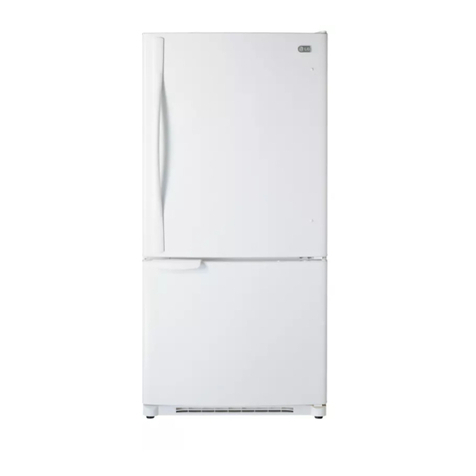
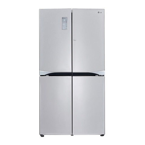
LG GC-B207GLQV User manual

CAUTION
PLEASE READ CAREFULLY THE SAFETY PRECAUTIONS OF THIS BOOK
BEFORE CHECKING OR OPERATING THE REFRIGERATOR.
REFRIGERATOR
SERVICE MANUAL
http://biz.lg vice.comres
SALES MODEL:GC-B207GLQV

WARNINGS AND PRECAUTIONS FOR SAFETY ............................................................................................... ..................... 3
................. ...........................................................................................................................................14
SPECIFICATIO SN
PARTS IDENTIFICATION....................................................................................................................................................... .15
HOW TO INSTALL THE REFRIGER ATOR .................................................................................................................... 16
MICOM FUNCTION ..............................................................................................................................................................17-19
EXPLATION FOR MICOM CIRCUIT.....................................................................................................................................20-32
62-02 ..............................................................................................................................TIUCRICBWPROFNOITANALPXE
COMPENSATION CIRCUIT FOR WEAK-COLD, OVER-COLD 92-72 ................................................MOORGNIZEERFTA
13-03..............................................................................................................................TSILDNAGNIWARDSTRAPBWP
23...........................................................................................................................................................................TIUCRIC
19-353................................................................................................................................................SISONGAIDELBUORT
26-35 ...................................................................................................................................................GNITOOHSELBUORT
97-36..........................................................................................................................................................................STLUAF
68-08..............................................................................................................................RIAPERYVAEHELCYCGNILOOC
19-78....................................................................................................................................SMIALCHTIWLAEDOTWOH
HOW TO DISASSEMBLE AND ASSEMBLE ..................................................................................................................... 92-93
DOOR...............................................................................................................................................................................92
HANDLE ...........................................................................................................................................................................93
EXPLODED VIEW ..............................................................................................................................................................94-98
CONTENTS
- 2 -
COMPRESSOR .................................................................................................................................................................. 4-7
......................................................................................... 8-13
Heavy Repair Method of Refrigerator by Application of Refrigerant
MICOM ERR 15-33 ...................................................................................................................................................EDOCRO
ERROR CODE SUMMARY ...........................................................................................................................................
33-34
TROUBLE SHOOTING WITH ERROR .....................................................................................................................
35-52

Please observe the following safety precautions in order to
use safely and correctly the refrigerator and to prevent
accident and danger during repair.
1. Be care of an electric shock. Disconnect power cord
from wall outlet and wait for more than three minutes
before replacing PWB parts. Shut off the power
whenever replacing and repairing electric components.
2. When connecting power cord, please wait for more than
five minutes after power cord was disconnected from the
wall outlet.
3. Please check if the power plug is pressed down by the
refrigerator against the wall. If the power plug was
damaged, it may cause fire or electric shock.
4. If the wall outlet is over loaded, it may cause fire. Please
use its own individual electrical outlet for the refrigerator.
5. Please make sure the outlet is properly earthed,
particularly in wet or damp area.
6. Use standard electrical components when replacing
them.
7. Make sure the hook is correctly engaged.
Remove dust and foreign materials from the housing
and connecting parts.
8. Do not fray, damage, machine, heavily bend, pull out,
or twist the power cord.
9. Please check the evidence of moisture intrusion in the
electrical components. Replace the parts or mask it
with insulation tapes if moisture intrusion was
confirmed.
10. Do not touch the icemaker with hands or tools to
confirm the operation of geared motor.
11. Do not let the customers repair, disassemble, and
reconstruct the refrigerator for themselves. It may
cause accident, electric shock, or fire.
12. Do not store flammable materials such as ether,
benzene, alcohol, chemicals, gas, or medicine in the
refrigerator.
13. Do not put flower vase, cup, cosmetics, chemicals,
etc., or container with full of water on the top of the
refrigerator.
14. Do not put glass bottles with full of water into the
freezer. The contents shall freeze and break the glass
bottles.
15. When you scrap the refrigerator, please disconnect the
door gasket first and scrap it where children are not
accessible.
WARNINGS AND PRECAUTIONS FOR SAFETY
- 3 -
Chapter 8 Compressor
1. Inverter Linear Compressor
Check for defect of the inverter linear compressor in following orders:
1-1. Method to Measure Compressor Winding Resistance
Normal Determination Criteria
The compressor winding resistance can be determined as normal if resistance values show the values as described in below figure
when measuring resistance values of the harness (connected with compressor) to connect Connect201(CON201) of the main PWB
as shown in below figure.
Defect Determination Criteria
Check connection status of the Compressor Connection Harness-P(Lead Wire) which is located at the M/Croom where resistance
values measured at the CON201 Housing are shown as infinite or several hundred . Separate connecting wires of the M/C room
(A-point in Figure) and then measure resistance values at the connecting wires again. The compressor can be determined as
normal if resistance values are shown as standard resistance value.
Check connection status of a harness.
(Defect at M/C room connection contact or CON201 Housing contact, short-circuit of harness)
Where resistance values measured at A-point are also shown as infinite or several hundred , disassemble a coverPTC of the
compressor terminal and check the terminal connecting status at the B-point in Figure.
Where there is no failure in the wiring status and resistance values are shown as infinite or several hundred , it may be
determined as defect of compressor.
Since if there is no failure in resistance values of the compressor, it may be defectiveMain PWB, replace the Main PCB and check
for normal operation of the compressor.
When determining any defect through resistancemeasuring, it can be determined as normal if resistance values show as descried
in the below figure by measuring①power and ③common terminal
resistance values are measured when measuring①power but measuring is meaningless since they cannot become
criteria for determining defect (measuring not required).
Caution
1. Be sure to powering off the refrigerator and measure after several minutes has passed.
2. If not accurately measuring resistance, wrong determination may be guided. (Difference of resistance value of several W or so may
occur.)
COMPRESSOR
●
●
●
●
●
-4-

1-2.Method to Determine Defect of Inverter Linear Drive
Determination of Comp Operation
Separate the back cover at the rear of refrigerator and determine for possible operation while touching the compressor with thehands
with insulation gloves worn.
Comp Operation
- Determine possible trip by checking operation status if cold air comes out after opening the doors of the R-Room.
Protective Logic (Trip)
- To protect the compressor from abnormal operation, this logic is used to temporally stop the refrigerator when abnormal operation
occurs and to re-operate it after abnormal signal disappears.
COMPRESSOR
Division operation condition Delay time LED time
Stroke Trip Stroke > 16.8mm 1mintue 2times
Current Trip Running Cap. voltage
voltage
Vcap > 540Vrms ( 59.5Hz 1.82Arms, 61Hz 1.86Arms) 6 mintues 6times
Lock Piston Trip Stroke < 5mm, Running Capacitor Vcap > 300V (= 1Arms)2.3mintues 5times
Overload Protection 运转频率61Hz, 以Stroke 限制运转状态 连续运转5小时0second
0second
4times
IPM Fault IPM Send Fault signal to IPM 7times
-5-

Fuse Inspection
- Visually inspect for fuse broken.
- When a fuse is destroyed, visually inspect for breaking of IPM and IC209 and additionally check it with a multi-test.
Inverter Parts Inspection
- Visually inspect for breaking of IPM and IC209 and additionally check it with a multi-test (check for short).
Bridge Diode Inspection
- Bridge diode is considered as destroyed if value of10W or less is shown in every case when measuring resistance with a multi-test
for 2 terminals of 4 diode terminals.
※Power should be turned on again after checking all parts because series of detects may occur when powering on in a simple parts
defect status for parts defect related with an inverter.
COMPRESSOR
-6-

Parts Defect Determination in Power On Status
Check of Power Application
-Check that supply power of +15V, +8V used as supply power of digital circuits is normally applied.
COMPRESSOR
+15V +8v
Measuring part
D202 Pin2-GND D203 Pin2-GND
Normal 13V-15.5V 7V-9V
Defect 13V or less 7V or less
Measures Replace board Replace board
-7-

Chapter 9 Heavy Repair Method of Refrigerator by Application of
Refrigerant
1. Outline
1-1. Checkpoints before Heavy Repair
Open the Cover ASM, Back-M/C of refrigerator and check the type of refrigerant indicated on a compressor before starting work.A
yellow label is adhered to the compressor for the refrigerator using R600a as refrigerant.
1-2. Features of R600a Refrigerant
Non-polar natural gas refrigerant (CH(CH3)3)
Since R600a is same series as butane gas, there is danger of fire when discharged into air at appropriate concentration (extreme
handling is required for heavy repair of cycle).
Explosion concentration: .8% ~ 8.4%/Vol.
Burning temperature: 494℃
1-3. Features of R600a Refrigerator
With refrigerant quantity of 60% or so for the refrigerator using R134a as refrigerant
Large vacuum level at suction pressure (at low pressure side)
COMP capacity of the refrigerator using R609a as refrigerant is large by 1.7 times than that of the refrigerator using R134a.
Labels as in Figure are displayed at the compressor of a refrigerant for R600a and the back plate of refrigerator.
1-4. Location and Environment for Heavy Repair
Check that drafting and air ventilation are well done at a working area and perform work after making drafting and air ventilation
smooth (use refrigerant return bag indoors).
Check that there are fire appliances or heating source around the working area and then remove them before work.
Since R600a refrigerant is very inflammable, they should not be discharged indoors.
Be sure to follow heavy repair SVC procedures during work.
1-5. Heave Repair Work Tool
R600a refrigerant
Bombe
Pinch Pliers
Refrigerant Discharge Hose
Refrigerant Return Bag
Vacuum Pump
Handy Welding Machine
Charging Tube
Leakage Tester
Drier
Heavy Repair Method of Refrigerator by Application of Refrigerant
Insulation Blowing Gas : Cyclopentane
15mm
●
●
●
●
●
●
●
●
●
●
●
●
●
●
●
●
●
●
●
●
-8-

2. Heavy Repair SVC Method
For the heaver repair of R600a type of refrigerator, perform work according to following SVC method.
2-1. Returnof Refrigerator Refrigerant
Required equipment: Pinch pliers, refrigerant discharging hose, refrigerant returnbag
Take power cords out and remove power between 6sec through 12sec after powering ON to open all both sides of 3way valve.
Leave doors of a refrigerator so that they are not closed.
Connect pinch pliers with a refrigerant discharging hose.
Place the outlet of a refrigerant discharging hose outside.
(Remove fire appliances or heating sources near a refrigerant discharging hose.)
Always use a refrigerant returnbag for working at the contained space.
Bore the charging pipe of a compressor with pinch pliers.
(Remove fire appliances or heating sources near a refrigerator.)
Perform refrigerant discharge for more than 7 minutes.
Heavy Repair Method of Refrigerator by Application of Refrigerant
●
●
●
●
●
●
●
-9-

2-2. Returnof Remained Refrigerant
Required equipment: Pinch pliers, hose for refrigerant recovery, vacuum pump
If refrigerant returntime of 7 minutes has passed, connect a vacuum pump at the ends of a
refrigerant returnhose outdoor. (Vacuum pump must operate outdoor.)
Operate a vacuum pump in order to returnrefrigerant remained in the pipe.
Vacuum working time should be for more than 10 minutes.
2-3. Welding Repair Step
Required equipment: Simple welding machine
Remove pinch pliers if remaining refrigerant returnis completed.
Cut the front part of a process pipe with a cutter. (Check that remaining refrigerant comes out.)
Perform welding work such as replacement of compressor and dryer, or repair of leakage part. (Be cautious of fire during welding
work.)
Heavy Repair Method of Refrigerator by Application of Refrigerant
●
●
●
●
●
●
-10-

2-4. Charging Tube Connection Step
Required equipment: Charging tube, simple welding machine
Remove a charging pipe to recharge R600a refrigerant after completing work, and then connect a charging tube with welding
2-5. Vacuum Air Removal
Required equipment: Vacuum pump
Connect a vacuum pump to a charging tube to perform vacuum cycle.
Vacuum work should be performed for an hour. (If vacuum time is short, normal cooling performance may not be exerted due to
failure of cooling cycle.)
Heavy Repair Method of Refrigerator by Application of Refrigerant
●
●
●
-11-

2-6. Refrigerant Charging
Required equipment: Bombe, R600a refrigerant (80g)
Firstly remove fire appliances and heating source for performing work when charging scaled refrigerant. (Do not spray refrigerant
indoor.)
Measure the accurate quantity (80g) of refrigerant to charge it into a Bombe.
Make the Bomber as vacuum status to charge refrigerant.
(If there is air or moisture in a Bombe, it may give effect on performance of a cooling cycle.)
Please manage refrigerant quantity as 80g±1. Differently from R134a, R600a gives much effect on
cooling performance depending on change of refrigerant quantity.
Refrigerant quantity = Weight after charging– Weight before charging (weight of vacuumed Bombe)
Connect Bombe with a charging tube to charge refrigerant.
Turn on power of refrigerator to operate a compressor.
Measure Bombe weight after 5 through 10 minutes to check remained refrigerant quantity to complete charging of refrigerant.
(After charging refrigerant, never perform welding work or work using fire appliances.)
2-7. Leak Inspection and Cycle Check
Required equipment: Leakage checking machine (foam and leakage inspection machine)
Check for leakage by using form or a leakage inspection machine at the worked part if charging of refrigerant is completed.
Check for leakage at the low pressure part with the compressor stopped, and check at the high pressure part with the compressor
being operating.
If leakage is detected, proceed to repair according to repair process again starting from“2-1. Returnof Refrigerator Refrigerant”.
(Never perform welding work or work using fire appliances.)
Check that heat remains at a discharge pipe or condenser with the hands if leakage check is completed. If heat remains, the
cooling cycle is normal.
(Take care since a discharge pipe may be hot.)
Heavy Repair Method of Refrigerator by Application of Refrigerant
●
●
●
●
●
●
●
●
●
●
●
-12-

2-8. Failure Checking Procedures
Heavy Repair Method of Refrigerator by Application of Refrigerant
-13-

SNOITACIFICEPS
- 14 -
SMETI SNOITACIFICEPS
DIMENSIONS(mm) 894(W)
X
725(D)
X
1753(H)
NET WEIGHT (kg) 110
METSYSGNILOOC Fan Cooling
lortnoCmociMLORTNOCERUTAREPMET
METSYSGNITSORFED Full Automatic
Heater Defrost
NOITALUSNI Cyclo-Pentane
ROSSERPMOC epyTgnitratS.C.T.P
ROTAROPAVE epyTebuTniF
CONDENSER Wire Condenser
REFRIGERANT R600a (80g)
LIOGNITACIRBUL FREOL @10G (310 cc)
DRIER 38.0DI
>weiVtnorF< >weiVenalP<
.cepsledoM.3
SMETI SNOITACIFICEPS
EBUTYRALLIPAC MOLECULAR SIEVE XH-7
TSORFEDTSRIF 4 - 5 Hours
ELCYCTSORFED 13 - 15 Hours
ECIVEDGNITSORFED htaehS,retaeH
retaeHrepmaDRETAEHGNIZEERF-ITNA
PMALREZEERF 40W (1 EA)
PMALROTAREGIRFER 40W (1 EA)
5 2 7
571 3
4

PARTS IDENTIFICATION
- 15-
Frame Display
Cover PWB
.oNfeR.2

1. How to Adjust Door Height of Refrigerator
dellatsnitonsirotaregirferehtfI(.tsriflevelrotaregirferehtekaM yamroodrotaregirferdnarezeerffothgieheht,roolftalfehtno
not be the same.
1. If the height of freezer door is lower than that of
refrigerator compartment :
2. If the height of freezer door is higher than that of
refrigerator compartment :
Insert a driver into the groove of adjusting screw
and rotate driver in arrow direction (clockwise) until the
refrigerator becomes horizontal.
Insert a driver into the groove of adjusting screw
and rotate driver in arrow direction (clockwise) until the
refrigerator becomes horizontal.
HOW TO INSTALL REFRIGERATOR
-16-
1
1
2
2
Adjusting
Adjusting
revirD
revirD
Even if the height can not be aligned by
using the height adjustment screw,insert
the transparent sheet supplied with the
product.
Bot tekcarbmot
snarT par teehstne
Bot egnihmot
Separate the door with the lower height,
use the (+) type screwdriver to unscrew
the screw at the botton hinge as shown
at figure , insert the transparent sheet
between the bottom hinge and the bottom
bracket,and then fix it with the screw as
shown at figure .
Insert more transparent sheets enough to
align the height.(4 sheets are supplied in
total.)

1. Monitor Panel
MICOM FUNCTION
-17-
2-1. Funnction of Temperature Selection
. .noitidnocdaolehtnognidnepedC°5.1±yravnacerutarepmetehT*
1. When power is initially applied or reapplied after power cut, “Medium” is automatically selected.
2. When the temperature selection switch in the freezer and refrigerator compartments is pressed, the light is on in the
following sequence:
"Middle" "Middle Strong" "Strong" "Weak" "Middle Weak"
3. The temperature setting condition of freezer and refrigerator compartments shall not be indicate in the standard model
( GC-A217L) when refrigerator or home bar door is closed.
Divisio Initially On
nPower 1st
Press 2nd
Press 3th
Press 4th
Press 7th
Press 8th
Press 9th
Press 10th
Press 11th
Press
-
19 °C
4 °C
-
19 °C
4 °C
-
20 °C
3 °C
-
21 °C
2 °C
-
22°C
1 °C
-
23 °C
7 °C
-
15 °C
4 °C
-
16 °C
3 °C
-
17 °C
2 °C
-
18 °C
1 °C
-
19 °C
7 °C
-
20 °C
3 °C
-
21 °C
2 °C
-
22°C
1 °C
-
23 °C
7 °C
-
15 °C
4 °C
-
16 °C
3 °C
-
17 °C
2 °C
-
18 °C
1 °C
-
19 °C
7 °C
Change
of
Indication
Lamp
Temperature
Temperature
Contro l
Middle Middle
5th
Press
-
24 °C
6 °C
-
24 °C
6 °C
Strong
6th
Press
-
14 °C
5 °C
-
14 °C
5 °C
Weak
Middle
Strong Middle
Strong Strong Strong Weak Weak Middle
Weak Middle
Weak
Freezer
Freezer
Temperature
Contro l
Refrigeration
Refrigeration
Contro l

MICOM FUNCTION
-18-
1
2
3
The control of variable-speed fan in freezer
The fan motor in freezer should change speed from Standard to High to increase the cooling speed.
High speed is used only on initial power on or when loading relevant operations. Standard speed is
used in normal operating conditions.
When the freezer or the refrigerator is open or the fan motor in the freezer is in operation (If fan motor
is rotating in high speed, the speed changes from High to Standard.).
2-3
2-2
.Door open alarm
1.When the doors of the refrigerator, freezer or home bar are kept open for 1 minute or longer, a
buzzer will sound.
2.When the door is kept open for 1 minute, the buzzer will sound 3 times at an interval of 0.5
second. After that, the buzzer sounds 3 times at the first 0.5 second of every 30 seconds.
3.The alarm will be deactivated when the doors of the refrigerator, freezer or home bar are closed.
times times times
minute 30s 30s
2-4.Buzzer sound selection button
1.Press the button on the front display for a “Ding” sound.
2-5.Buzzer alarm of forced start and forced defrost
1.Press the test button on the main PWB for a “Beep” sound.
2.When forced start is selected, the alarm sounds 3 times, on for 0.2 second and off for 1.8 second.
3.When forced defrost is selected, the alarm sounds 3 times in the following cycle: 0.2 sec
(on)-0.2 sec (off), 0.2 sec (on)-0.2 sec (off), 0.2 sec (on)-1.0 sec (off)
2-6.Defrost function
1. Under normal conditions, defrost is carried out when the accumulated operating time of the
compressor reaches 50 hours (with the doors closed). If a door has been opened, the time is
reduced by 8 minutes every second the door is opened. For defrost to be carried out, the
minimum accumulated operating time of the COMP is 7 hours.
2.On initial power-on or when repower after cutting off the power supply, defrost starts when the
accumulated operating time of the compressor reaches 4 to 4.5 hours.
3.When the defroster sensor temperature reaches 5°C, defrosting is complete. If the sensor
cannot reach 5°C after 80 minutes of defrosting, it indicates defrosting failure.
4.If the defroster sensor is defective (Wire broken or shorted), defrosting may not work.
R room,F room
or homebar
buzzer
off on off on
1minute 130s
3times 3 3 3
off

-19-
FUNCTION REMARK
2-7.Electrical device operation sequence
MICOM FUNCTION
When initial power-on and test is finished, electrical devices such as compressor,
defrosting heater, cooling fan, stepping motor damper operate in the following
sequence to reduce the noise and component damage.
The defroster
sensor tempe-
rature is over
45℃(After pur-
Defroster sensor
temperature is
below 45℃
(After cutting off
the power or
repair)
No initial
start in
case of
function
error
Load start
sequence
when the
freezer
door and
refrigerator
door are
closed
Test mode 1
(Forced start)
Test mode 2
(Check the
freezer fan)
In TEST
MODE 2, if
the S/W is
pressed
againor the
temperature
is higher
than 5℃
initial driving
starts after
returning
from the
TEST MODE
(7minutes after
the COMP).
chase or moving
in the house)
defroster
sensor
Test
mode
r e w o p l a iti n I g n i y l p p a n I
Load Operation Sequence
POWER
ON
F-FAN
&
C-FAN
ON
DAMPER
OPEN
0.6s 60s
Damper
Heater
ON
COMP
ON
0.3s
Valve
Initial
0.5s
Valve
Open
60s
0.3s
POWER
ON
F-FAN
&
C-FAN
ON
DAMPER
OPEN
0.6s 60s
Damper
Heater
ON
COMP
ON
0.3s
Valve
Initial
0.5s
Valve
Open
60s
0.3s
POWER
ON
Defrost
Heater
ON
0.3s 10s
DC
Heater
ON
F-FAN
&
C-FAN
ON
5s
Defrost
Heater
OFF
H-Bar
Heater
ON
0.3s 5s H-Bar
Heater
OFF
5s DAMPER
OPEN
60s
COMP
ON
Valve
Initial
0.5s Valve
Close
0.5s
Valve
Open
60s
0.3s
POWER
ON
Defrost
Heater
ON
0.3s 10s
DC
Heater
ON
F-FAN
&
C-FAN
ON
5s
Defrost
Heater
OFF
H-Bar
Heater
ON
0.3s 5s H-Bar
Heater
OFF
5s DAMPER
OPEN
60s
COMP
ON
Valve
Initial
0.5s Valve
Close
0.5s
Valve
Open
60s
0.3s
Other
Heater
OFF
C-FAN
ON DAMPER
OPEN
0.3s
TEST
S/W
(Press
once)
0.6s
COMP
ON
0.3s F-Fan
ON
30s
Valve
Open
0.5s
Other
Heater
OFF
C-FAN
ON DAMPER
OPEN
0.3s
TEST
S/W
(Press
once)
0.6s
COMP
ON
0.3s F-Fan
ON
30s
Valve
Open
0.5s
F-FAN
&
C-FAN
OFF
F-Fan
&
C-Fan
ON
DAMPER
CLOSE
0.3s 0.3s
TEST
S/W
(Press 2
Times)
0.6s
COMP
OFF
0.3s Valve
Close
0.5s
F-FAN
&
C-FAN
OFF
F-Fan
&
C-Fan
ON
DAMPER
CLOSE
0.3s 0.3s
TEST
S/W
(Press 2
Times)
0.6s
COMP
OFF
0.3s Valve
Close
0.5s

1. Explanation for PWB circuit
1-1. Power circuit
1. GC-A207W/R207W
Power circuit consists of SMPS (SWITCHING MODE POWER SUPPLY) power. The SMPS consist of the rectifying part
(BD1, CE1) converting AC voltage to DC voltage, the switching part (IC2) switching the converted DC voltage, transformer
transferring energy of the primary side of the switching terminal to the secondary side and the feedback part (IC3, IC4)
transferring it to the primary side.
Caution : Since high voltage (DC310V) is maintained at the power terminal, please take a measure after more than 3
minutes have passed after removing power cords in the abnormal operation of a circuit.
Voltage of every part is as follows:
EXPLATION FOR MICOM CIRCUIT
- 20 -
Part VA1
CE201
CE3 CE4 CE26 CE5
Voltage 230 Vac 310 Vdc 16 Vdc 12 Vdc 6.5 Vdc 5 Vdc
This manual suits for next models
1
Table of contents
Other LG Refrigerator manuals

LG
LG GL-D201AHPY User manual

LG
LG GN-V312RLCA User manual

LG
LG LFX25992 series User manual

LG
LG GBB59PZFZB User manual

LG
LG GL-M492GGLJ User manual

LG
LG G Series User manual

LG
LG GSJ960MCCZ User manual

LG
LG GM-652RC Series User manual

LG
LG LFX25950SB - 24.7 Cu.Ft. Refrigerator User manual

LG
LG LMX25984ST/01 User manual