5-1-2. Food storage/seasoning function
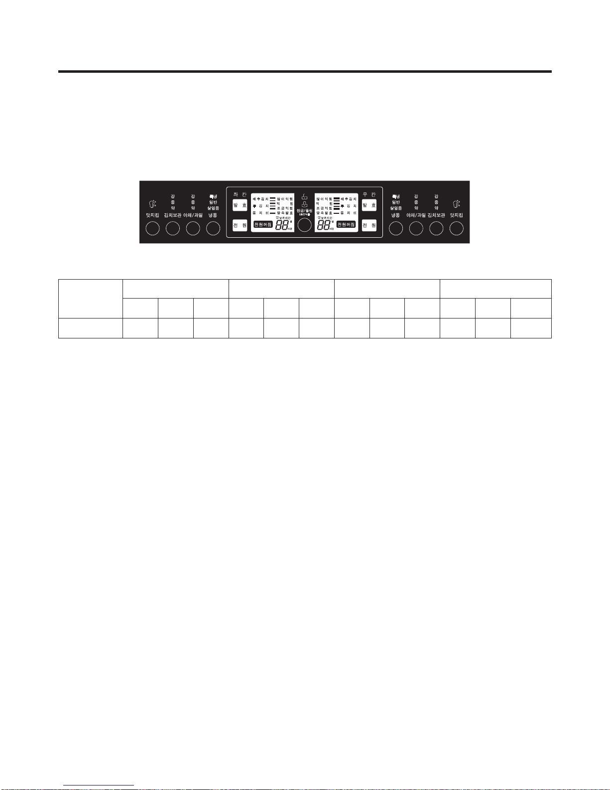
(1) When selecting food type and storing temperature
1. Press the “Lock/Unlock” button for more than 2 seconds to switch to “Unlock” status.
2. Press the “Kimchi store” button to select “Mid” ’ “Max” ’ “Min” ’ “Mid”, “Vegetable / Fruit” button “Mid” ’ “Max” ’ “Min”
’ “Mid”, and “Feezing” button “Normal” ’ “Max” ’ “Ligth Freeaing” ’ “Normal” in sequence
3. Press the “Lock/Unlock” button to complete the selection of food type and storing temperature. At this time, if a minute
passes without pressing the “Lock/Unlock” button, it will automatically switch to Lock status and end the food type and
storing temperature selection mode.
(2) When selecting rhythm fermenting (seasoning)
1. Press the “Lock/Unlock” button for more than 2 seconds to switch to “Unlock” status.
2. At this condition, press “Fermentation” button to select “Normal ” ’ ”Normal ” ’ ”More ” ’ ”Underground
Fermentation ” ’ ”Less ” ’ ” Less ” ’ ” Normal ” in sequence, and when the fermentation type is changed
from “Less” to “Normal”, the food type is selected by the order of “Cabbage kimchi” ’ ”Radish kimchi” ’ ”Broth kimchi”
in sequence. However, “Underground Fermentation ” is only for “Cabbage kimchi.”
3. Press the “Lock/Unlock” button to complete the rhythm fermenting (seasoning). At this time, if a minute passes without
pressing the “Lock/Unlock” button, it will automatically switch to Lock status and end the rhythm ferment (seasoning)
selection mode.
4. When “Rhythmic fermentation” is terminated, the remaining time is displayed, and when the fermentation is completed, “0
hour” is displayed as the remaining time and the storing temperature is automatically set to “Mid
(3) When selecting flavor keeping
1. Press the “Lock/Unlock” button for more than 2 seconds to switch to “Unlock” status.
2. Select “Kimchi store” as storing type. (Flavor keeping function is only limited to “Kimchi store”)
3. At this time, press the “Flavor keeping” button to select or cancel the flavor keeping function.
4. Press the “Lock/Unlock” button to end the flavor keeping selection mode. At this time, if a minute passes without pressing
the “Lock/Unlock” button, it will automatically switch to Lock status and end the flavor keeping selection mode.
5. If you select flavor keeping during seasoning process, it will immediately end the seasoning and switch to flavor keeping.
At this time the storing temperature will automatically be set to “Mid”.
6. If you select the flavor keeping function, the refrigerator will lower the temperature to maintain the current Kimchi flavor.
(-1 degrees for “Min”, -0.5 degrees for “Mid” and -0 degrees for “Max”.)
7. During flavor keeping operation, a cold shock operation is done every 12 hours.
8. If you select rhythm fermenting during flavor keeping, the flavor keeping function will be canceled.
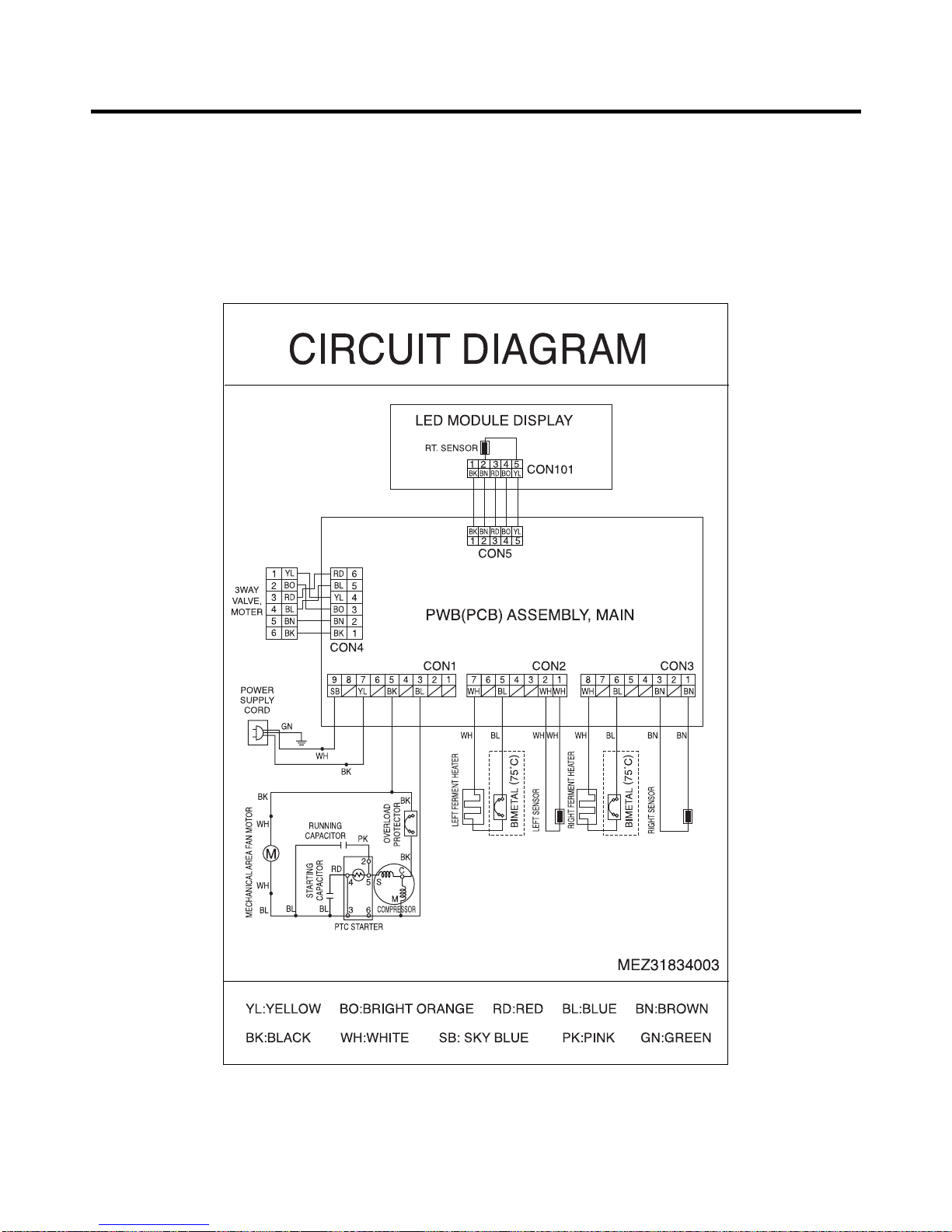
MICOM function and circuit description
- 10 -