LG LFC23760ST - Bottom Freezer Refrigerator User manual

CAUTION
BEFORE SERVICING THE UNIT,
READ THE SAFETY PRECAUTIONS IN THIS MANUAL.
REFRIGERATOR
SERVICE MANUAL
MODELS:
LFC23760ST / 04
LFC23760SW / 04
LFC23760SB / 04

ECN (Engineering Change Number)
Rev.01
Change Cover Lower (improve structure)
SVC Improvement opening door freezer (Change connector rail in order to reduce claims for bad sealing and
door misaligned. New connector rail has 1º degree of inclination)
Rev.02
Valve inclined in order to improve house connection
Rev.03
Change model to Barrierless type & Twisting Ice Maker
Rev.04
Compressor change from MQ53LAUM (PTC) to MQ53LAUM (e-PTC)

CONTENTS
SAFETY PRECAUTIONS ........................................................................................................
1. SPECIFICATIONS ...............................................................................................................
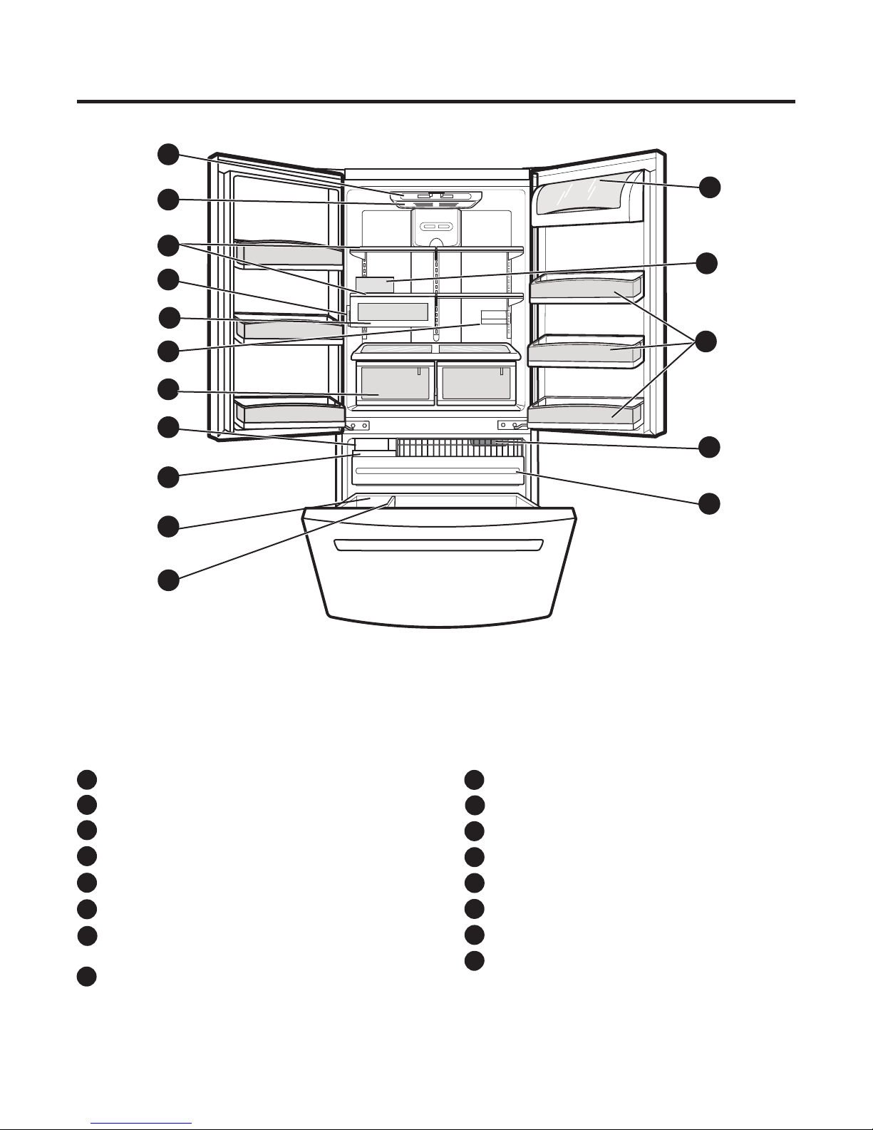
2. PARTS IDENTIFICATION ....................................................................................................
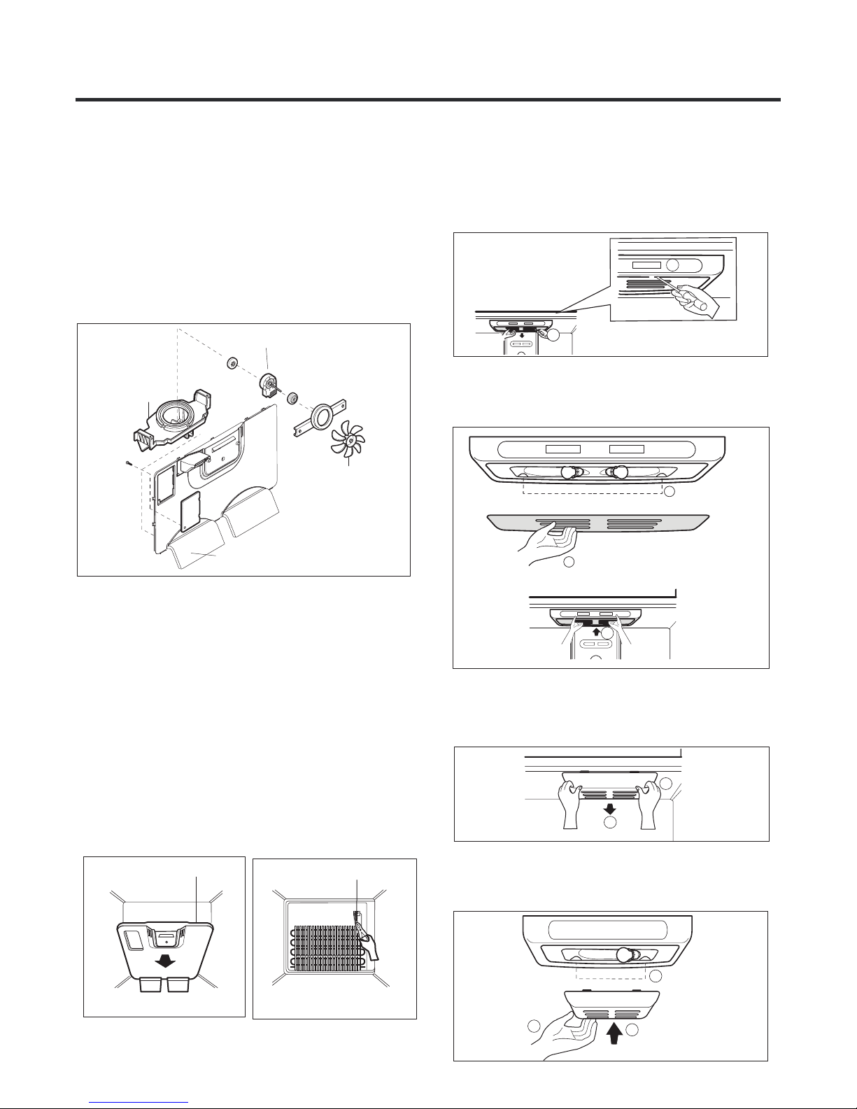
3. DISASSEMBLY ...................................................................................................................
3-1 Fan and Fan Motor..........................................................................................................
3-2 Defrost Control Assembly.................................................................................................
3-3 Lamp................................................................................................................................
3-4 Control Box Refrigerator..................................................................................................
3-5 Multiduct..........................................................................................................................
3-6 Cover Valve......................................................................................................................
3-7 Door Disassembly............................................................................................................
3-8 How to remove the Door Handle.....................................................................................
3-9 How to remove Pull out drawer........................................................................................
3-10 Closing and aligning the doors......................................................................................
4. ADJUSTMENT ....................................................................................................................
4-1 Compressor ...................................................................................................................
4-2 PTC-Starter ....................................................................................................................
4-3 OLP (overload protector) ...............................................................................................
5. CIRCUIT DIAGRAM ............................................................................................................
6. TROUBLESHOOTING ........................................................................................................
6-1 Compressor and electric components ...........................................................................
6-2 PTC and OLP .................................................................................................................
6-3 Other electrical components ..........................................................................................
6-4 Service diagnosis chart ..................................................................................................
6-5 Refrigeration cycle .........................................................................................................
7. OPERATION PRINCIPLE AND REPAIR METHOD OF ICEMAKER ..................................
7.1 Operation principle .........................................................................................................
7.2 Ice maker functions ........................................................................................................
8. CIRCUIT OF MICOM............................................................................................................
8.1 Function .........................................................................................................................
8.2 PCB function ..................................................................................................................
8.3 Resistance specification of sensor .................................................................................
9. EXPLODED VIEW ................... ............................................................................................
3
4
5
6
6
6
6
7
7
9
10
12
14
16
17
17
17
18
19
20
20
21
22
23
24
26
26
27
30
30
34
38
39
- 2 -

- 3 -
SAFETY PRECAUTIONS
Please read the following instructions before
servicing your refrigerator.
1.Check the refrigerator for current leakage.
2.To prevent electric shock,unplug before
servicing.
3.Always check line voltage and amperage.
4.Use standard electrical components.
5.Don't touch metal products in the freezer
with wet hands.This may cause frost bite.
6.Prevent water from spiling on to electric
elements or the machine parts.
7.Before tilting the refrigerator, remove all
materials from on or in the refrigerator.
8.When servicing the evaporator, wear gloves
to prevent injuries from the sharp evaporator
fins.
9.Service on the refrigerator should be
performed by a qualified technician.Sealed
system repair must be performed by a CFC
certified technician.

1. SPECIFICATIONS
- 4 -
LFC23760SW /04 LFC23760ST /04 LFC23760SB /04
Super White Stainless Black
PCM Stainless VCM
Yes (2) 40W/Blue
No
1Fix(S/Proof)+1Fold+2S/Out(S/Proof)
Embo (normal)
Vista
ICE PLUS
3 left + 3 right
Anti-freezing Heater
Drier
Full Automatic
Heater Defrost
Cyclo, Pentane
MQ53LAUM PTC Starting Type
4 Hours
7 - 40 Hours
Heater, Sheath
Water Tank Heater
FREEZER
Basket, Quantity
Tray meat
Lamp
Shelf
No
Yes (1) 40W/Blue
No
Egg Bank
REFRIGERATOR
Case Material
Door Material
Handle Type
Display Graphic
Lamp
Shelf
Ice Tray & Bank
Basket, Quantity
Compressor
Fin Tube Type
Wire Condenser
Polyol Ester (POE) RL-7H/7 cst 220 ± 10cc
First Defrost
Condenser
Lubricanting Oil
ID Ø0.75
Cooling System
Rated Rating
Climate class
Yes (Cover + Egg tray)
1B/(1EA)
MOLECULAR SIEVE XH-7
Defrost Cycle
Desfrosting Device
Evaporator
Capillary Tube
Temperature Control
Defrosting System
Insulation
MODELS
SPECIFICATIONS
Capacity
Refrigerant
Net Weight
Dimensions
GENERAL FEATURES
Color
R134a
Temperate (T)
115V~ / 60Hz
MICOM control
892 (W) x 925 (D) x 1860 (H) mm
123 Kg
23 cuft
Fan Cooling

DIMENSIONS
Depth w/ Handles
Depth w/o Handles
Depth w/o Door
Depth (Total with Door Open)
Height to Top of Case
Height to Top of Door Hinge
Width
Width (door open 90 deg. w/o handle)
Width (door open 90 deg. w/ handle)
A
B
C
D
E
F
G
H
I
Description
LFC23760**
28 ¼
36 ¼
41 ¼
45 ½
32 ¾
67 11 16
34 58
32 18
69 116

- 5 -
2. PARTS IDENTIFICATION
* On some models
ADigital Sensor Control
Durabase
Durabase Divider
Egg Compartment *
Refrigerator Door Rack
Freezer Light
Pull out Drawer
B
C
D
F
E
G
H
I
J
K
L
M
N
O
P
Ice Bin
Optibin Crisper
Keeps fruits and vegetable fresh and crisp
Chef Fresh / Snack Pan
Can Dispenser *
Temperature Control *
Shelves
Refrigerator Light
Icemaker
Dairy Compartment
*
A
B
C
G
H
I
J
E
F
K
D
L
M
N
O
P
below. The location of some of the parts may not correspond to that of your model.
Read this section to familiarize yourself with the parts and features of your new refrigerator.
NOTE: This guid ecovers different models. Your refrigerator could have some or all of the features and parts listed

* On some models
ADigital Sensor Control * Durabase
Durabase Divider
Egg Compartment *
Refrigerator Door Rack
Freezer Light
Pull out Drawer
B
C
E
D
F
G
H
N
O
I
J
K
L
M
Ice Bin
Optibin Crisper
Keeps fruits and vegetable fresh and crisper
Chef Fresh / Snack Pan
Can Dispenser *
Shelves
Refrigerator Light
Icemaker
Dairy Compartment
A
B
C
G
H
I
D
E
J
K
L
N
O
F
M
Read this section to familiarize yourself with the parts and features of your new refrigerator.
NOTE: This guid ecovers different models. Your refrigerator could have some or all of the features and parts listed
below. The location of some of the parts may not correspond to that of your model.
- 6 -

GRILLE ASSEMBLY DEFROST-CONTROL
ASSEMBLY
GRILLE
FAN MOTOR
BRACKET
MOTOR
FAN
3-1 FAN AND FAN MOTOR
1. Remove the freezer shelf. (If your refrigerator has an
icemaker, remove the icemaker first).
2. Remove the plastic guide for slides on left side by
unscrewing phillips head screws.
3. Remove the grille by removing one screw and pulling the
grille forward.
4. Remove the Fan Motor assembly by loosening 2 screw and
disassemble the shroud.
5. Pull out the fan and separate the Fan Motor and Bracket.
3-2 DEFROST CONTROL ASSEMBLY
Defrost Control assembly consist of Drefrost Sensor and
FUSE-M.
The Defrost Sensor works to defrost automatically. It is
attached to the metal side of the Evaporator and senses its
temperature.
Fuse-M is safety device for preventing over-heating of the
Heater when defrosting.
At 72°C, it turns the Defrost Heater off.
1. Pull out the grille assembly. (Fig. 1)
2. Separate the connector with the Defrost Control assembly
and replace the Defrost Control assembly after cutting the Tie
Wrap. (Fig. 2)
1. Unplug your refrigerator.
2. Pull out all of the shelves.
3. Slide a flat screwdriver (1) into the opening of the
light bulb, and pull it downwards (2).
3-3 LAMP
3-3-1 REFRIGERATOR COMPARTMENT LAMP
3-3-2 FREEZER COMPARTMENT LAMP
1. Unplug refrigerator.
2. Unlock the cover of the light bulb using your thumbs (2).
3. DISASSEMBLY
- 7 -
1
2
1
2
4. Turn the bulb counter clockwise and remove it.
5. Install the new light bulb.
6. Take the cover (1), lock the hooks (2) from the rear part
of the light bulb and push it upwards (3).
1
2
3
1
2
1
2
3. Remove the light bulb and replace it with a new one.
4. Take the cover (3), lock the hooks of it (4) and push it
upwards (5).
5. Plug the refrigerator back in.
4
5
3
Fig. 1 Fig. 2

3-5 MULTI DUCT
1. Remove an upper and lower Cap by using a flat screwdriver, and loosen 2 screws.
2. Disconnect the lead wire on the botton position.
3-4 CONTROL BOX-REFRIGERATOR
CONTROL BOX
COVER LAMP
1. First, remove all shelves in the refrigerator, than remove the Refrigerator control Box by loosening 2 screws.
2. Remove the Refrigerator Control Box by pulling it downward.
3. Disconnect the lead wire on the right position and separate the lamp sockets.
- 8 -

- 9 -
3-6 VALVE COVER (in some models)
3-6-1 DISASSEMBLE 3-6-2 ASSEMBLE
1. Unscrew the back cover.
2. Unscrew the valve from the back side.cover
3. Push to the left and release.
1. Insert the ribs tothe right side ofthe back hole.cover
2. Screw the valve from the back side.cover
3. Screw the back .cover

- 10 -
1. To remove Refrigerator door
3-7 DOOR DISASSEMBLY
IMPORTANT: Before you begin, turn the refrigerator OFF and
Unplug it. Remove all food and the shelves from the doors.
Left Door
Right Door
NOTE: The appearance of the handle might be different.
With the Philips screw driver, loose the two screws from
the upper lid (1) remove it after that.
1
2
With the 10mm socket wrench, loose the two pins from the
hinge (3) and remove it (4).
3
4
Unplug the switches cable (2) it’s optional, it’s no neccesary
do it for removing the door.
Place the door with the inner face over the surface so it
won't scratch.
5
Unplug the switches cable (6) it’s optional, it’s no
neccesary do it for removing the door.
6
Unplug the cable harness pulling up the hook located in
the upper part of it (7) and separate both parts of the
Upper view of
the harness
harness (8).

Loose the grounding screw (9) and the pins (10) located
over the hinge, after, lift the hinge and remove it (11).
8
Remove the door and place it over its inner face to avoid
scratching.
Right Door
Take the door and place it gently over the pin of the
1
Pin
Be sure the hook (2) (located in the upper part of the door)
matches with the divisor of the refrigerator's door (3).
Check that the sealing patch of the door is leveled to the
refrigerator and that it isn´t bended.
9
10
11
hinge (1).
7
Front view of
the harness
Place the hinge in its original position (4) assembly the
two pins (5) and the ground screws (6).
Plug the cable harness (7) and the switch (8) (just in case
7
8
4
5
6
3
2
Right Door
if you unplugged the switch).
Place the hinge lid (9) and install both screws (10). Be
sure the door is correctly assembled.
9
10
2. To install Refrigerator door
- 11 -

Take the left door and place it over the hinge (11).
Place the hinge in its original position (14) and place the
two screws (15).
Left Door
13
12
15
14
Be sure that the hook (12) located in the upper part of the
door) matches with the splitter of the refrigerator (13).
Check that the sealing patch of the door ends leveled with
the refrigerator and that it isn't bended.
11
Left Door
Plug the cable to the switch (16) (just in case if you
16
Place the hinge's lid (17) and screw the two screw (18).
Check that the door is well installed.
18
17
Loose the screws (1) with the Allen tool 3/32” and remove
the handle (2).
Remove the mounting screws with the ¼” Allen tool (3).
Mounting
Screws
Allen Wrench
Screws
1
2
3
unplugged the switch).
3-8 HOW TO REMOVE DOOR HANDLE
- 12 -

Install the mounting screws over the door (1) place the
1. To install the handle of the refrigerator
handle over them (2) and tight the screws up (3).
2. To remove the freezer's handle
With an 3/32” Allen tool, loose the screws (1) located on
from the door (3) with an ¼” Allen tool.
the bottom of the handle, remove it (2) remove the screws
Mounting
Screws
Screws
3
2
1
Wrench
Allen
3
2
1
3
3. To install the freezer's handle
Install the mounting screws over the door (1) place the
handle over them (2) and tight the screws up (3).
1
2
3
1
- 13 -

- 14 -
3-9 HOW TO REMOVE PULL OUT DRAWER
IMPORTANT: To avoid possible injury or damage to the
product or your property, please use two people to perform
the following instructions:
1. Removing the Pull Out Drawer
•Pull the drawer out to maximum extension. Remove the
bottom rack (1) by tilting it back a little and then lifting it
•Put pressure on the two hangers (2) with your thumbs in
•Remove the screws (3) from both sides of the rail track.
1
off the railing tracks.
order to lift it up.
Separate the left and right rail cover.
•
2
3
CAUTION: When removing the drawer, do not hold the
handle. If it comes off, it could cause personal injury.
CAUTION: To place the drawer on the floor, take care
not to damage the floor or hurt your feet with the sharp
edges on the side with the hinges.
•With both hands, hold both sides of the door and pull up
to separate it.
•With both hands, hold the center of the bar and push it
in so that it is fit to both rails simultaneously.
2. Installing the Pull Out Drawer
•With both hands, hold the center of the bar and pull it
outward so that the two rails extend out at the same
time.

•Mount door supports (1) into the tabs on the railing
•Push the drawer down into position and tighten the
•Compare the left and right rail covers on each side.
1
2
3
track (2), starting in the back first and then connecting
the part in the front last, as shown in the figure.
screws (3).
Right
Rail
Left
Rail
•Align the top holes of the rail cover with the top holes of
the door supports to mount the cover.
•With the drawer fully extended, insert the lower basket
over the front part of the rail assembly and then the
WARNING: To prevent entrapment risk and accidental
child or animal suffocation, DO NOT permit them to
play inside of the drawer.
WARNING: DO NOT step ot sit on the Freezer Door.
alignment
Verify the hole’s
4
back part (4).
- 15 -

- 16 -
3-10 CLOSING AND ALIGNING THE DOORS
Open both doors again and check to make sure that
they close easily. If not, slightly tilt the refrigerator
further back by turning both leveling screws clockwise.
It may take several more turns. Make sure that you
turn both leveling screws the same amount.
Closing the Doors
Your refrigerator has two front leveling screws, one on the
right and one on the left. If your refrigerator seems
unstable or if you would like the doors to close more easily,
simply adjust the inclination of the refrigerator by following
1. Plug the refrigerator into a 3 prong grounded outlet.
Move the refrigerator into its final position.
2. Remove the base grille (Refer to the section on
“Installation of Base Grille”).
Use a flat head screwdriver to adjust the leveling
screws, turning clockwise to raise the side of the
refrigerator and counter-clockwise to lower it. It may
NOTE: Having someone push against the top of the
refrigerator takes some weight off the leveling screws.
This will make it easier to adjust the screws.
4.
5. Ensure that the refrigerator is even by using a level.
6. Replace the base grille.
the instructions below:
3.
take several turns to adjust it to the inclination you
would like.
Aligning the Doors
If the spacing between the doors is uneven, follow the
instructions below to align them:
1.
2.
3.
With one hand, lift up the door you want to raise at
middle hinge.
With other hand, use pliers to insert snap ring as
shown.
Insert additional snap rings until the doors are aligned.
(Three snap rings are provided per unit.)

4-1 COMPRESSOR
4-1-1 Role
The compressor intakes low temperature and low pressure
gas from the evaporator of the refrigerator and compresses
this gas to high-temperature and high-pressure gas. It then
delivers the gas to the condenser.
4-1-2 Composition
The compressor includes overload protection. The PTC
starter and OLP (overload protector) are attached to the
outside of the compressor. Since the compressor is
manufactured to tolerances of 1 micron and is hermetically
sealed in a dust and moisture-free environment, use
extreme caution when repairing it.
4-1-3 Note for Usage
(1) Be careful not to allow over-voltage and over-current.
(2) If compressor is dropped or handled carelessly, poor
operation and noise may result.
(3) Use proper electric components appropriate to the
Particular Compressor in your product.
(4) Keep Compressor dry.
If the Compressor gets wet (in the rain or a damp
environment) and rust forms in the pin of the Hermetic
Terminal, poor operation and contact may result.
(5) When replacing the Compressor, be careful that dust,
humidity, and soldering flux don’t contaminate the inside
of the compressor. Dust, humidity, and solder flux
contaminate the cylinder and may cause noise,
improper operation or even cause it to lock up.
4-2 PTC-STARTER
4-2-1 Composition of PTC-Starter
(1) PTC (Positive Temperature Coefficient) is a no-contact
semiconductor starting device which uses ceramic
material consisting of BaTiO3.
(2) The higher the temperature is, the higher the resistance
value. These features are used as a starting device for
the Motor.
4-2-2 Role of PTC-Starter
(1) The PTC is attached to the Sealed Compressor and is
used for starting the Motor.
(2) The compressor is a single-phase induction motor.
Durign the starting operation, the PTC allows current
flow to both the start winding and main winding.
4-2-3 PTC-Applied Circuit Diagram
Starting Method for the Motor
4-2-4 Motor Restarting and PTC Cooling
(1) It requires approximately 5 minutes for the pressure to
equalize before the compressor can restart.
(2) The PTC device generates heat during operation.
Therefore, it must be allowed to cool before the
compressor can restart.
4-2-5 Relation of PTC-Starter and OLP
(1) If the compressor attempts to restart before the PTC
device is cooled, the PTC device will allow current to
flow only to the main winding.
(2) The OLP will open because of the over current
condition. This same process will continue (3 to 5
times) when the compressor attempts to restart until
the PTC device has cooled. The correct OLP must be
properly attached to prevent damage to the
compressor.
Parts may appear physically identical but could have
different electrical ratings. Replace parts by part
number and model number. Using an incorrect part
could result in damage to the product, fire, injury, or
possibly death.
4-2-6 Note for Using the PTC-Starter
(1) Be careful not to allow over-voltage and over-current.
(2) Do not drop or handle carelessly.
(3) Keep away from any liquid.
If liquid such as oil or water enters the PTC,
PTC materials may fail due to breakdown of their
insulating capabilities.
(4) If the exterior of the PTC is damaged, the resistance
value may be altered. This can cause damage to the
compressor and result in a no-start or hard-to-start
condition.
(5) Always use the PTC designed for the compressor and
make sure it is properly attached to the compressor.
Parts may appear physically identical but could have
different electrical ratings. Replace parts by part
number and model number. Using an incorrect part
could result in damage to the product, fire, injury, or
possibly death.
PTC STARTER SEALED
TERMINAL
COMPRESSOR
MOTOR
C
M
SM
36
5
2
S
PTC
N
L1
OVERLOAD PROTECTOR
Resistance Starter Capacitor Running
Fig. 1
4. ADJUSTMENT
C
- 17 -

4-3 OLP (OVERLOAD PROTECTOR)
4-3-1 Definition of OLP
(1) OLP (OVERLOAD PROTECTOR) is attached to the
Compressor and protects the Motor by opening the
circuit to the Motor if the temperature rises and
activating the bimetal spring in the OLP.
(2) When high current flows to the Compressor motor, the
Bimetal works by heating the heater inside the OLP,
and the OLP protects the Motor by cutting off the
current flowing to the Compressor Motor.
4-3-2 Role of the OLP
(1) The OLP is attached to the Sealed Compressor used
for the Refrigerator. It prevents the Motor Coil from
being started in the Compressor.
(2) For normal operation of the OLP, do not turn the Adjust
Screw of the OLP in any way.
- 18 -
Part
Customer part
number
Lot code/
date code
330 FBYY -S1 BOX98
12345678
termination
part number
Electrical
characteristics
part number
No. Name
Base, phenolic
(UL 94 V-0 rated)
Movable arm support,
Stationary contact support,
plated steel
Heater support, plated steel
Heater, resistance alloy
Disc, thermostatic alloy
Movable arm, spring temper
copper alloy
Contact, movable, silver on copper
Contact, stationary, silver on copper
Slug, plated steel
Cover, polyester
(UL 94 V-0 rated)
Pin connector, plated copper alloy
(To engage 2.33/2.66 mm dia. pin)
(OVERLOAD PROTECTOR cross section)
Fig. 2
Physical
plated steel.
Other manuals for LFC23760ST - Bottom Freezer Refrigerator
2
This manual suits for next models
2
Table of contents
Other LG Refrigerator manuals
Popular Refrigerator manuals by other brands

KitchenAid
KitchenAid KSBS25FJBL00 parts list

Kelvinator
Kelvinator KHBF336HWF Instruction book

Panasonic
Panasonic NR-BN34EX1 operating instructions

Panasonic
Panasonic NR-BR34B operating instructions

Hisense
Hisense RB424N4CFC Detailed instructions for use

Danby
Danby Silhouette Select SSWC056D1B Owner's use and care guide