4
CAUTION
To reduce the risk of minor injury to persons, malfunction,
or damage to the product or property when using this
product, follow basic precautions, including the following:
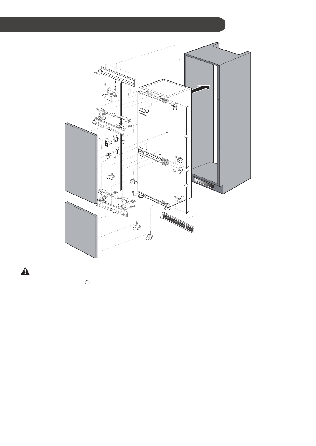
Installation
•Prepare cabinet work in accordance with the instructions to
assure adequate ventilation. Be sure that the installation has
unobstructed air flow into front air vent. If ventilation is not
adequate the normal performance of the appilance may be
impaired or prohibited.
•Install the cabinet door to the appliance in such a way to maintain
a 5 mm gap between the edge of the cabinet door and any
adjacent wall.
•Use the specified dimensions for the Integrated door panels.
Oversized integrated door panels may sag or cause interference
with the correct operation of the appliance.
•Check there is no lean on the appliacne door after attaching
the Integrated door panels. Check to see that the gasket of the
appliance is properly attached.
•Use Integrated panel material of sufficient strength to maintain
integrity of support screw/bolts under the weight of the panels. Do
not use material that will allow the screws to be pulled out easily
from the weight of the panels.
•Use Cabinet material that is sealed and will not warp or twist
from the heat generated by the appliance or from the moisture
produced by opening and closing the appliance doors.
•Install the appliance in a cabinet where the horizontal and vertical
sides are at right angles.
•For safety reasons keep children away from the installation
location and all installation materials during installation.