LG LSC27990TT User manual

CAUTION
PLEASE READ CAREFULLY THE SAFETY PRECAUTIONS OF THIS MANUAL
BEFORE CHECKING OR OPERATING THE REFRIGERATOR.
REFRIGERATOR
SERVICE MANUAL
MODEL : LSC27990TT COLOR : TITANIUM
http://aic.lgservice.com

WARNINGS AND PRECAUTIONS FOR SAFETY ................................................................................................................ 3
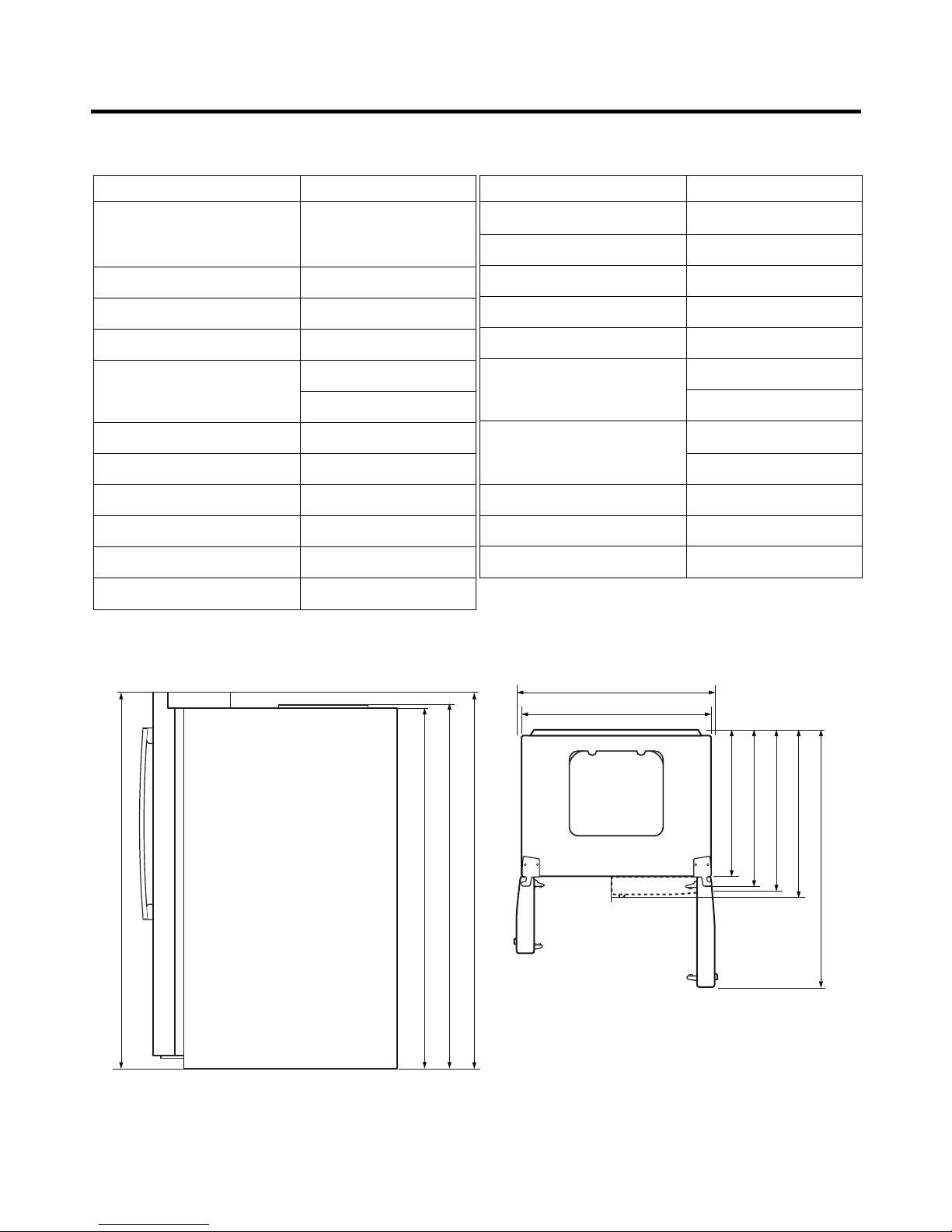
SPECIFICATIONS................................................................................................................................................................... 4
PARTS IDENTIFICATION ........................................................................................................................................................5
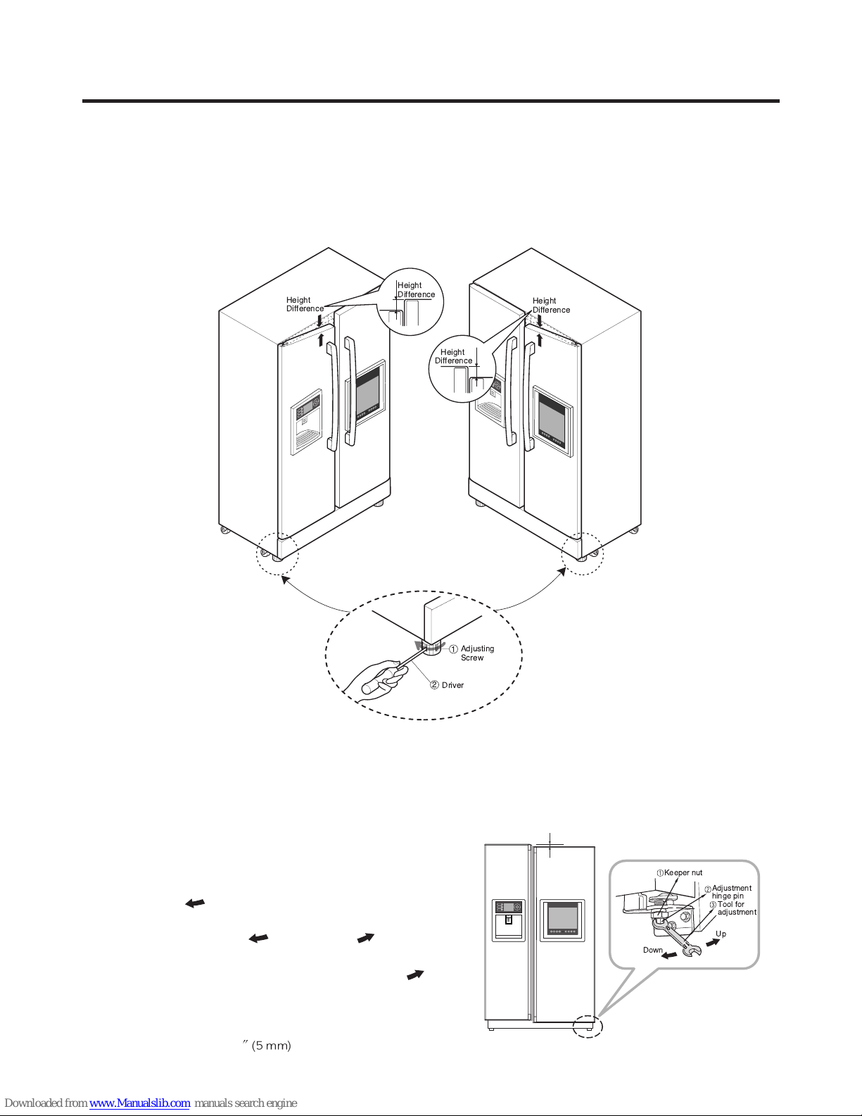
HOW TO INSTALL THE REFRIGERATOR ............................................................................................................................ 6
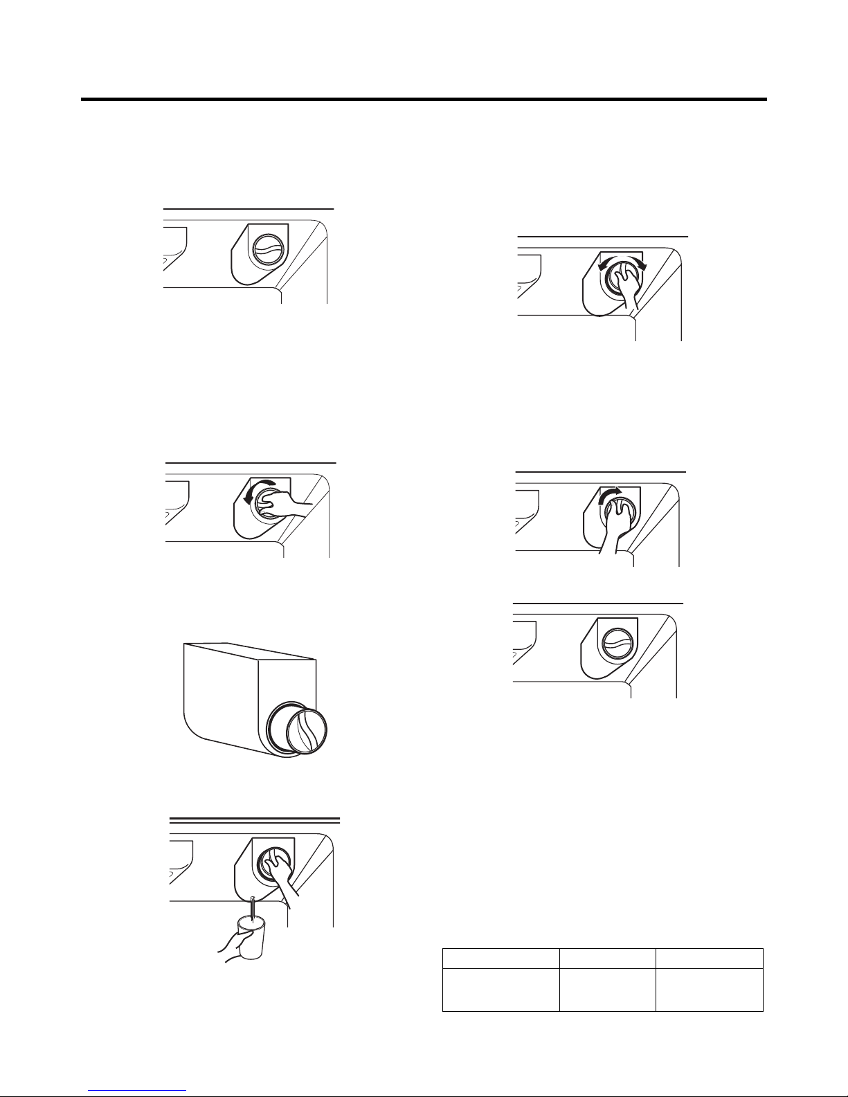
HOW TO ADJUST DOOR HEIGHT...................................................................................................................................... 6
FILTER ................................................................................................................................................................................. 7
HOW TO CONTROL THE ICEMAKER WATER SUPPLY.................................................................................................... 8
MICOM FUNCTION ................................................................................................................................................................ 9
EXPLANATION OF MICOM CIRCUIT ...................................................................................................................................22
EXPLANATION OF PWB CIRCUIT .....................................................................................................................................22
PWB PARTS DIAGRAM AND LIST.....................................................................................................................................37
PWB CIRCUIT DIAGRAM ...................................................................................................................................................43
ICEMAKER AND DISPENSER WORKING PRINCIPLES AND REPAIR ............................................................................45
WORKING PRINCIPLES.................................................................................................................................................... 45
FUNCTION OF ICEMAKER ............................................................................................................................................... 46
CIRCUIT................................................................................................................................................................................ 48
TROUBLE DIAGNOSIS........................................................................................................................................................ 49
TROUBLESHOOTING ....................................................................................................................................................... 49
FAULTS .............................................................................................................................................................................. 59
COOLING CYCLE HEAVY REPAIR ................................................................................................................................... 76
HOW TO DEAL WITH CLAIMS.......................................................................................................................................... 83
TV-RADIO ............................................................................................................................................................................. 88
SAFETY PRECAUTIONS................................................................................................................................................... 88
FEATURE ........................................................................................................................................................................... 88
CONTROLS........................................................................................................................................................................ 89
REMOTE CONTROL KEY FUNCTIONS ........................................................................................................................... 90
TROUBLESHOOTING ....................................................................................................................................................... 91
BLOCK DIAGRAM.............................................................................................................................................................. 92
TV PART DISASSEMBLE .................................................................................................................................................. 93
HOW TO DISASSEMBLE AND ASSEMBLE....................................................................................................................... 94
DOOR................................................................................................................................................................................. 94
HANDLE ............................................................................................................................................................................. 95
FAN SHROUD GRILLE ...................................................................................................................................................... 95
WATER VALVE DISASSEMBLY METHOD .........................................................................................................................96
FAN and FAN MOTOR DISASSEMBLY METHOD..............................................................................................................96
DISPENSER....................................................................................................................................................................... 97
EXPLODED VIEW ................................................................................................................................................................ 99
REPLACE PARTS LIST.......................................................................................................................................................106
CONTENTS
- 2 -

Please observe the following safety precautions to use the
refrigerator safely and correctly and to prevent accident or
injury when servicing.
1. Be careful of an electric shock. Disconnect the power
cord from wall outlet and wait for more than three
minutes before replacing PWB parts. Shut off the power
whenever replacing and repairing electric components.
2. When connecting the power cord, please wait for more
than five minutes after the power cord was disconnected
from the wall outlet.
3. Check if the power cord is pinched between the
refrigerator and the wall. If the plug or cord is damaged,
it could cause a fire or an electric shock
4. If the wall outlet is overloaded, it may cause a fire. Use a
dedicated circuit for the refrigerator.
5. Make sure the outlet is properly grounded.
Particularly in a wet or damp area.
6. Use standard electrical components.
7.Remove dust and foreign materials from the housing and
connecting parts.
8. Do not fray, damage, run over, kink, bend, pull out, or
twist the power cord.
9. Check for evidence of moisture intrusion in the
electrical components. Replace the parts or mask with
insulation tape if moisture intrusion was confirmed.
10. Do not insert fingers or tools into the icemaker. The
geared motor drive could cause an injury or damage to
tools or the icemaker .
11. Do not suggest that customers repair their refrigerator
themselves. This work requires special tools and
knowledge. Non-professionals could cause fire, injury,
or damage to the product.
12. Do not store flammable materials such as ether,
benzene, alcohol, chemicals, or gas.
13. Do not put anything on top of the refrigerator,
especially something containing water, like a vase.
14. Do not put glass bottles with full of water into the
freezer. The contents will freeze and break the glass
bottles.
15. When you scrap or discard the refrigerator, remove the
doors and dispose of it where children are not likely to
play in or around it.
16. This is a consumer grade product. It is not intended for
precise storage of medication.
WARNINGS AND PRECAUTIONS FOR SAFETY
- 3 -

SPECIFICATIONS
- 4 -
724 mm (281/2in.)
1004 mm (391/2in.)
908 mm (3911/16 in.)
779 mm (305/8in.)
829 mm (325/8in.)
897 mm (355/16 in.)
1261 mm (495/8in.)
1741.5 mm (681/2in.)
1746.5 mm (683/4in.)
1771 mm (6911/16 in.)
1. Ref No. : GR-G277STSA(LSC27990TT)
ITEMS SPECIFICATIONS
DIMENSIONS 908
X
896
X
1771 mm
W
X
D
X
H (3511/16
X
355/16
X
6911/16 in.)
NET WEIGHT 145 kg (319.7 lbs.)
COOLING SYSTEM Fan Cooling
TEMPERATURE CONTROL Micom Control
DEFROSTING SYSTEM Full Automatic
Heater Defrost
INSULATION Cyclo-Pentane
COMPRESSOR PTC Starting Type
EVAPORATOR Fin Tube Type
CONDENSER Wire Condenser
REFRIGERANT R134a (185g) (61/2oz.)
LUBRICATING OIL FREOL @10G (320 cc)
ITEMS SPECIFICATIONS
DRIER MOLECULAR SIEVE XH-7
CAPILLARY TUBE ID Ø0.83
FIRST DEFROST 4 - 5 Hours
DEFROST CYCLE 13 - 15 Hours
DEFROSTING DEVICE Heater, Sheath
ANTI-SWEAT HEATER Dispenser Duct Door Heater
Dispenser Heater
ANTI-FREEZING HEATER Water Tank Heater
Damper Heater
FREEZER LAMP 40W (1 EA)
REFRIGERATOR LAMP 40W (4 EA)
DISPENSER LAMP 15W (1 EA)
Front View Top View

1. Ref No. : GR-G277STSA(LSC27990TT)
PARTS IDENTIFICATION
- 5 -
Freezer
Compartment
Refrigerator
Compartment
Dairy Product Corner
Water Filter
Lamp
Drawer
Lamp
Automatic
Icemaker
Shelf
Door Rack
Drawer
Door Rack
Lower Cover OptiFresh Display Humidity Switch
Shelf
Shelf
Snack Drawer
Lamp
Bottle Guide
Vegetable Drawer
Door Rack
Door Rack
OptiFresh
Frame Display
Dispenser Lamp
Ice & Water
Dispenser Button
PWB Cover
Water Tubes

1. How to Adjust Door Height of Refrigerator
■Make the refrigerator level first. (If the refrigerator is not installed on a flat floor, the height of freezer and refrigerator
door may not be the same.)
1) If the freezer door is lower than the refrigerator
door:
2) If the freezer door is higher than the refrigerator
door:
Insert a driver into the groove of the adjusting
screw and turn in the direction of the arrow (clockwise)
until the refrigerator is level.
Insert a driver into the groove if the adjusting screw
and turn in the direction of the arrow (clockwise) until the
refrigerator is level.
3) When the refrigerator door is lower than the freezer door
Adjust the level when the refrigerator door is lower than the
freezer door during
the use of the refrigerator.
(1) Using the wide side of the tool for adjustment , turn the
keeper nut ( ) clockwise to loosen the keeper nut.
(2) Using the narrow side of the tool for adjustment, turn the
adjustment hinge pin ( ) clockwise or ( )
counterclockwise to level the refrigerator and freezer door.
(3) After setting the level of the door, turn the keeper nut ( )
counterclockwise to tighten.
Caution : Do not force too hard to level the height. The hinge
pin can be pulled out (Adjustable range of height:
Maximum of 2/10 ).
HOW TO INSTALL REFRIGERATOR
- 6 -
Adjusting
Screw
Driver
Height
Difference
Height
Difference
Height
Difference
1
2
Height
Difference
Keeper nut
Up
Down
Adjustment
hinge pin
Tool for
adjustment

2. Filter
Replace the filter when the indicator light comes on or the
performance of the icemker or water dispenser decreases
noticeably.
After changing the water filter cartridge, reset the water
filter status display and indicator light by pressing and
holding the FILTER Button for 3 seconds. (page 13)
1) Remove the old cartridge.
Twist the knob of the cartridge counterclockwise.
When the cartridge is removed, you will feel it click .
Pull out the cartridge.
NOTE: There will be some water (25cc) in the filter
cartridge. Some spilling may occur. Catch it in a
bowl or towel.
2) Replace with a new cartridge.
Take the new cartridge out of its packaging and remove
protective cover from the o-rings.
With cartridge knob in the vertical position, push the new
filter cartridge into the cover until it stops.
If you can’t turn the filter from side to side, it isn’t fully
inserted. Push it in firmly and twist it into place. You will
hear the snap when it clicks into place.
Using the handle, twist the cartridge clockwise about 1/4
turn.
3) Flush the Water System After Replacing Filter
Dispense water through the water dispenser for 3
minutes to purge the system.
There may be a little air in the line, causing noise or
hissing. Run the water at the dispenser until the hissing
stops to purge the air from the system.
NOTE: - To purchase replacement water filter cartridges,
visit your local appliance dealer or part distributor.
- You can also visit our website :
www.lgappliances.com or call 1-877-714-7481.
HOW TO INSTALL REFRIGERATOR
- 7 -
LG MDL PART NO MAKER
GR-G277STSA 5231JA2006A CUNO
(LSC27990TT)

3. How to Control the Amount of Water Supplied to Icemaker.
3-1. Confirm the amount of water supplied to the icemaker.
1) Confirm the amount of water supplied to the icemaker
(1) Press the button (Figure 1) to selsct the level of water (Optimum level Large Small.)
2) Icemaker Operation Test (Test mode)
(1) Press the button (Figure 1) for more than 3 seconds and It will start the Test mode.
(2) Test the operation of the operating part of the icemaker.
(3) If there is no problem with the operation, water is supplied through the water tube (up to the
selected lebel of water).
(4) The test mode is completed after the water is supplied.
Note : When using the test mode more than twice consecutively, water can overflow.
When the water overflows, wipe the ice storage bin.
* It is acceptable if the adjusted level of water is a bit smaller than optimum level.
HOW TO INSTALL REFRIGERATOR
- 8 -
Water Amount
Indicator Light
Power
Switch
Water Amount
Selection Button
Feeler
Arm
Check water level
Figure 1.

1. Monitor Panel
1-1. GR-G277STSA(LSC27990TT)
MICOM FUNCTION
- 9 -
Temperature Adjust Button
MENU Selection Button Dispenser Selection Button Lock Button Door Alarm Button
Dispenser Light Button
Calendar & Anniversary Reminder

1-2. Display Second Function
1. Door Alarm Buzzer Mute Mode
Press button to the buzzer on or off.
2. Demo Mode
Demo mode is available for displaying the refrigerator in a sales setting or similar condition.
It allows the display, dispenser, lights, and fan to operate without running the compressor.
To enter the DEMO mode, press and hold the TEMPERATURE and button simultaneously for 5 seconds until the
Ding~ sounds in the lock status.
To exit the DEMO mode and return to normal operation, press and hold the TEMPERATURE and button
simultaneously for 5 seconds until the Ding~ sounds again in the lock status.
The refrigerator will default to the NORMAL mode (DEMO mode OFF) if the power fails.
2. LCD Check Mode
Press TEMPERATURE and button simultaneously for 1 second in the lock status.
4. Communication Data Check Mode
Press MENU and button simultaneously for 6 seconds in the lock status.
MICOM FUNCTION
- 10 -
Door Alarm Buzzer
Mute Mode
Communication Data Check Mode
LCD Check Mode
Demo Mode

2. Description of Function
2-1-1. Function of Temperature Selection
* The temperature can vary ±5°F (±3°C) depending on the load condition.
❉Whenever pressing button, setting is repeated in the order of COLD ➝COLDER ➝COLDEST ➝COOL ➝COLDER.
•The actual inner temperature varies depending on the food status, as the indicated setting temperature is a target
temperature, not actual temperature within refrigerator.
•Refrigeration function is weak in the initial time. Please adjust temperature as above after using refrigerator for minimum
2~3 days.
•Freezer Notch is fixed COLDER unconcerned with display Notch during Icemaking Control Mode and Icemaker Stop
switch is selected with ON.
2-1-2. Outside temperature display function
1. The ambient temperature sensor is located under the upper right hinge cover. This sensor reads the
temperature of the room and displays it in the upper right corner of the display.
2. The ambient temperature is displayed between 16 °F and 120 °F. Outside of that range, the display will
show Er.
3. Since the ambient temperature sensor is located at the hinge, its reading may differ from other
thermometers in the room.
MICOM FUNCTION
- 11 -
Division Power Initially On 1st Press 2st Press 3th Press 4th Press
Setting
Temperature
Temperature
Control COLD COLDER COLDEST COOL COOLER
Freezer Control
-2 °F -5 °F -8 °F7°F1°F
Refrigeration 37 °F 34 °F 32 °F 46 °F 41 °F
Control

2-1-3. Lock function
1. If desiring to lock the dislay the dispenser and control panel, push on button more than 3 seconds.
Lock icon is appeared at the right of display with lock status.
2. The buzzer sound and control panel and dispenser function is not performed even if pressing display button other than
lock key in the lock status.
3. If desiring to release the lock status and pressing the lock button more than 3 seconds. Lock icon is disappeared at the
right of display with the lock release status.
2-1-4. Filter condition display function
1. There is a replacement indicator light for the water filter cartridge on the dispenser.
2. Water filter needs replacement once six months.
3. You will see a reminder pop-up window in the LCD screen 2 weeks before / 1 week before / due date to replace the filter
to notify you that the filter needs to be replaced.
4. If you want to reset the filter,use the Menu → Refrigerator → Filter Reset menu.
MICOM FUNCTION
- 12 -
LED

2-2. Dispenser use selection
You can select water or ice.
❉Select WATER, CRUSHED ICE, or CUBED ICE by pressing the DISPENSER button as you desire.
❉Use your cup to press lightly on the actuator.
•Each graphic is indicated for the selected function.
•You’ll hear a CLICK when the ice door closes 5 seconds after ice is dispensed.
REFERENCE : Hold your cup in the dispenser for a few seconds after dispensing
ice or water to catch the last few drops or pieces of ice.
2-3. ICE PLUS Freezing
Select this function to expedite freezing.
•Turn on/off the IcePlus function using the IcePlus button within the Temperature function.
•The "IcePlus" icon remains at the ON status after animation when selecting Special Refrigeration IcePlus FRZ
•ICE PLUS freezer function automatically turns off after a set time.
2-4. Dispenser Light
•The dispenser light function is repeated following below whenever pressing button.
MICOM FUNCTION
- 13 -
Pressing
Switch
<ON> <OFF>

2-5. ICE PLUS freezing
1. ICE PLUS freezing is a function to increase the cooling speed of the freezer compartment by running both the
compressor and the fan simultaneously.
2. ICE PLUS is cancelled and the refrigerator returns to its default setting in the event of a power interruption.
3. Selecting ICE PLUS changes only the speed of the cooling without affecting the set temperature.
4. The temperature can be adjusted even when ICE PLUS has been selected and is in progress.
5. The freezer operates at whatever temperature was set at the time ICE PLUS was selected.
6. If you select ICE PLUS, the compressor and fan will run until it is deselected or the cycle time has elapsed.
(3 hours : compressor and fan run / 3 ~ 24 hours : COLDEST operation)
7. If a defrost cycle occurs while an ICE PLUS is already running, ICE PLUS runs for its remaining cycle time after the
defrost cycle is completed. If the defrost cycle takes longer than 30 minutes, ICE PLUS will run for only 2 hours at the end
of the defrost cycle.
8. If you press ICE PLUS during a defrost cycle, the ICE PLUS indicator will illuminate but the compressor will not operate
until the defrost cycle is complete.
9. If you press ICE PLUS within 7 minutes of compressor cut-off, the compressor will not operate until the 7-minute delay
has passed.
10. The freezer fan motor runs at high speed during the ICE PLUS cycle.
2-6. OptiFresh Function
1. The OptiFresh bin is positioned at the bottom of the refrigerator compartment and has a separate temperature control to
allow perfect storage of fruits and vegetables.
2. OptiFresh comprises of OptiFresh sensor at the rear of OptiFresh and a damper between OptiFresh and Freezer
compartment and a temperature adjusting display at the top of it.
3. When powered on, the initial NOTCH of OptiFresh display will be on OptiFresh Crisper.
If only the refrigerator door is opened, the OptiFresh LED will be ON.
4. The OptiFresh sensor opens and closes the damper based on the temperature.
5. The OptiFresh damper will cycle every hour to prevent icing up.
•Press the button to toggle between ON and OFF.
MICOM FUNCTION
- 14 -

2-7. Control of variable type freezing fan
1. To increase cooling speed and response to load, the MICOM will vary the speed of the freezer fan between low and high.
2. The MICOM runs the fan at high speed only at power-up and for ICE PLUS cycles, and runs at low speed for all other
settings.
3. If you open the freezer door, the refrigerator door, or the home bar door, and the freezer fan was running at high speed, it
will reduce to low speed. If it was running at low speed when a door was opened, it will turn off.
4. If the MICOM determines the BLDC fan motor is locked up, (no signal for 115 seconds) it will show a failure code on the
display and cut power to the fan. To power the fan again, unplug the refrigerator for a few seconds and plug it in again.
2-8. Control of cooling fan motor
1. The cooling fan motor performs ON/OFF control by linking with the COMPRESSOR.
2. It controls at the single RPM without varying RPM.
3. Failure sensing method is same as in fan motor of freezing fan motor (refer to failure diagnosis function table for failure
display).
2-9. Door opening alarm
1. The buzzer sounds when any door is held open for more than one minute.
2. After any door has been open for one minute, the buzzer sounds three times for second each, then it sounds three
times for second each every thirty seconds until the door is closed.
3. When all open doors have been closed, the buzzer stops.
2-10. Ringing of button selection buzzer
1. If pressing the front display button, Ding ~ sound rings.
MICOM FUNCTION
- 15 -
Doors of freezer,
refrigerator, or
home bar.
BUZZER
Closing
Opening
Less than
one minute
One minute
30
seconds
30
seconds
30
seconds
Opening
Closing Closing
3 Times 3 Times 3 Times 3 Times

2-11. Ringing of manual operation, manual frost defrost buzzer
1. The buzzer sounds briefly when the test button on the main PCB is pressed.
2. If you select manual operation, the buzzer sounds three times for 2/10 second each, then it sounds three times for 2/10
second each every thirty seconds until the door is closed.
3. If you select manual defrost, the buzzer sounds three times for 2/10 second each, then it sounds three times for 2/10 second
each every thirty seconds until the door is closed.
2-12. Defrost function
1. Defrost is cycled whenever the compressor’s runtime reaches 7 ~ 7 hours.
2. In providing initial power (or returning power failure), defrost starts whenever total operation time of compressor becomes
4 ~ 4 hour.
3. Defrost is completed if temperature of a frost removal sensor becomes more than 5°C after starting frost removal. Poor
frost removal is not displaced if it does not arrive at 5°C even if two hours have passed after starting frost removal.
4. No defrost cycle is run if the defrost sensor fails.
2-13. Refrigerator room lamp automatic off
•Refrigerator room lamp turn on and off by refrigerator door switch.
•If refrigerator room lamp continuously turns on more than 7 minutes, the refrigerator room lamp turns off automatically.
MICOM FUNCTION
- 16 -

2-14. Sequential operation of components
Component products such as compressor, frost removal heater, freezing room fan, cooling fan, and step motor damper are
sequentially operated as follows for preventing noise and part damage occurred due to simultaneous operation of many
parts in applying initial power and completing test.
MICOM FUNCTION
- 17 -
Function Load Operation Sequence Remark
In applying Initial power TEST MODE
When temperature
of a frost removal
sensor becomes
more than 45°C
(At purchase,
shipping)
If error occurs
during operation,
initial operation is
not done.
■Sequence of
load operation
when closing
FREEZER and
REFRIGER-
ATOR.
If you press the
switch in the
again test mode 2
or temperature of
a frost removal
sensor is more
than 5°C, it
immediately
returns to the test
mode for initial
operation
(COMPRESSOR
operates after 7
minutes).
When
temperature of a
frost removal
sensor becomes
less than 45°C
(In power failure,
service)
Test mode 1
(Manual function)
Test mode 2
(Manual frost
removal)
POWER
ON
COMP
ON
F-FAN
&
C-FAN
ON
R-STEP
MOTOR
DAMPER
ON
OPTICHILL
STEP
DAMPER
MOTOR
ON
FROST
REMOVAL
HEATER
OFF
FROST
REMOVAL
HEATER
ON
DAMPER
&
DUCT DOOR
&
OPTICHILL
HEATER ON
DAMPER
&
DUCT DOOR
&
OPTICHILL
HEATER OFF
0.3
sec.
6.0
sec.
0.3
sec.
0.3
sec.
0.3
sec.
0.3
sec.
PIPE
&
DISP'
HEATER
OFF
0.3
sec. COMP
ON
0.3
sec. F-FAN
&
C-FAN
ON
0.3
sec. R-STEP
MOTOR
DAMPER
ON
0.3
sec.
OPTICHILL
STEP
DAMPER
MOTOR
ON
PIPE
&
DISP'
HEATER
ON
TEST
SWITCH
(PRESS
Once)
OTHER
LOAD
OFF
COMP
ON
F-FAN
&
C-FAN
ON
R-STEP
MOTOR
DAMPER
ON
OPTICHILL
STEP
DAMPER
MOTOR
CLOSE
TEST
SWITCH
(PRESS
2 Times)
COMP
OFF
F-FAN
&
C-FAN
OFF
FROST
REMOVAL
HEATER
ON
R-STEP
MOTOR
DAMPER
CLOSE
0.3
sec.
0.3
sec.
0.3
sec.
0.3
sec.
0.3
sec.
0.3
sec.
0.3
sec.
0.3
sec.
0.3
sec.
0.3
sec.
0.3
sec.
POWER
ON

2-15. Failure Diagnosis Function
1. Failure diagnosis facilitates service when a failure code shows during product operation.
2. When a failure is detected, the buttons are deactivated.
3. If a failure code is released, the MICOM resets and normal operation continues.
4. The failure code is displayed on the display screen. All display graphics that are not part of the failure code are turned off
(1) GR-G277STSA(LSC27990TT)
MICOM FUNCTION
- 18 -

✻LCD check function: If simultaneously pressing TEMPERATURE and button for a second in the lock status, a
back light is turned on and all display LCD graphics on. If releasing the button, the LCD graphic
displays the previous status.
MICOM FUNCTION
- 19 -

2-16. Test Function
1. The test function assists in diagnosing the PWB and determining the exact mode of failure.
2. The test button is on the main PCB. When test mode is engaged, it will complete its test cycle and default to normal
operation within 2 hours.
3. The buttons are disabled while the test mode is in effect.
4. When you have finished running test mode, unplug the refrigerator to reset it to normal operation.
5. If a failure is detected during test mode, release the test mode to display the failure code.
6. If a failure code is displayed, the test mode cannot be started.
MICOM FUNCTION
- 20 -
Test 1
Test 2
Normal
Status
Mode Operation Contents Remarks
Press test button once
(strong cold mode)
Press test button once at
the test mode 1 status
(forced defrost mode)
Press test button once at
the test mode 2 status
1. Continuous operation of compressor
2. Continuous operation of freezing BLDC motor
(high-speed RPM) and cooling BLDC motor
3. Defrost heater turns off
4. Stepping motor damper is completely opened
(baffle is closed)
5. OptiFresh stepping motor damper is
completely closed.
6. All display LCD graphics turn on.
1. Compressor OFF
2. Freezing BLDC motor and cooling BLDC
motor turn off
3. Defrost heater turns on
4. Stepping motor damper is completely closed
(baffle is closed)
5. OptiFresh stepping motor damper is
completely closed.
Return to the initial status.
Freezer fan turns off when
door is opened.
Return to the normal mode
when the defrost sensor is
above +5°C (+41°F)
Compressor will operate
after delay for 7 minutes
01
02
<TEST MODE 1> <TEST MODE 2>
Other manuals for LSC27990TT
6
Table of contents
Other LG Refrigerator manuals

LG
LG SXS Refrigerator User manual

LG
LG LTT581BB Series User manual

LG
LG GM-L261BNRY User manual

LG
LG LBNC12231 Series User manual

LG
LG LMX28983ST Installation guide

LG
LG LSC27921 Series User manual

LG
LG LSC27918 series User manual

LG
LG GN-M352RLCC User manual

LG
LG GR-B197WVS User manual

LG
LG LFC21776ST User manual