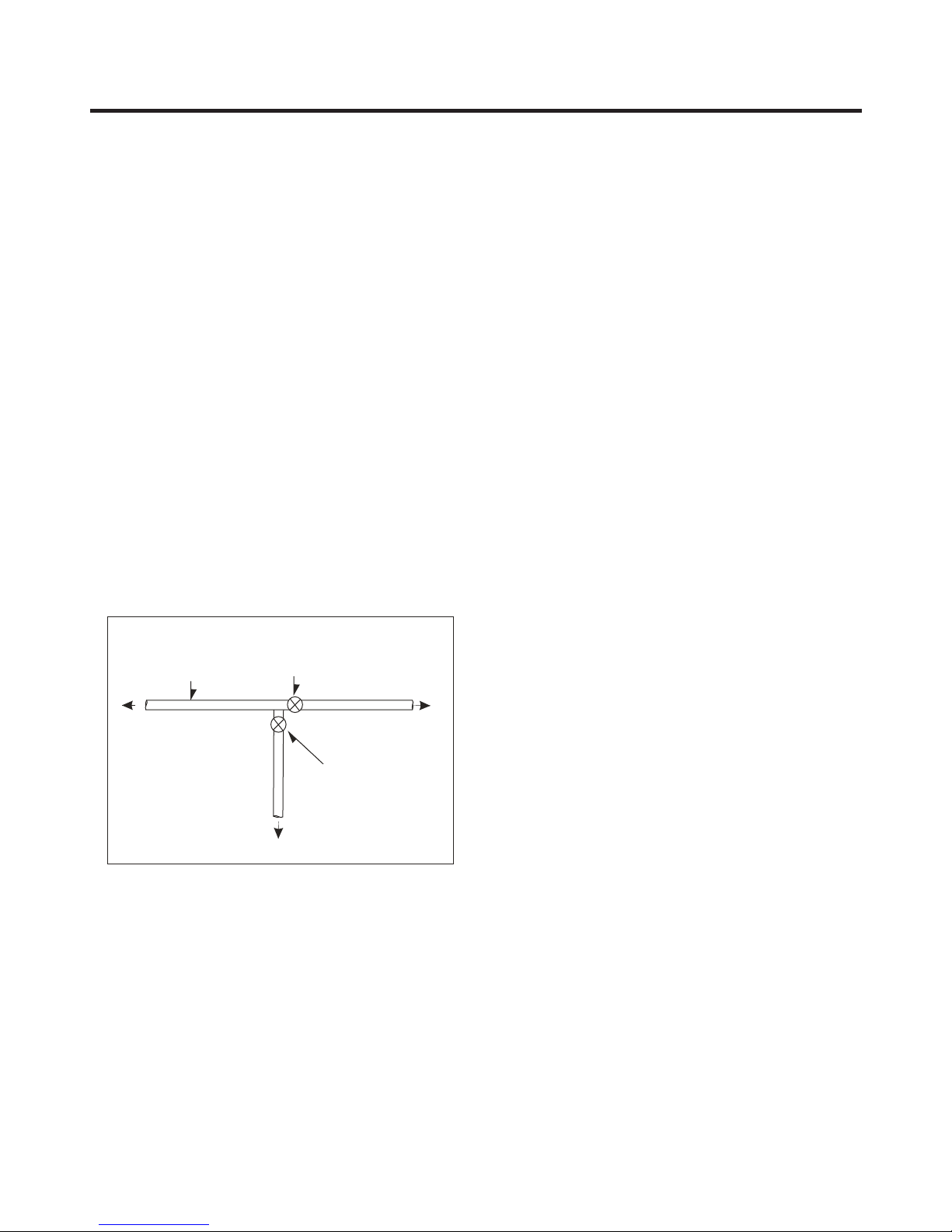
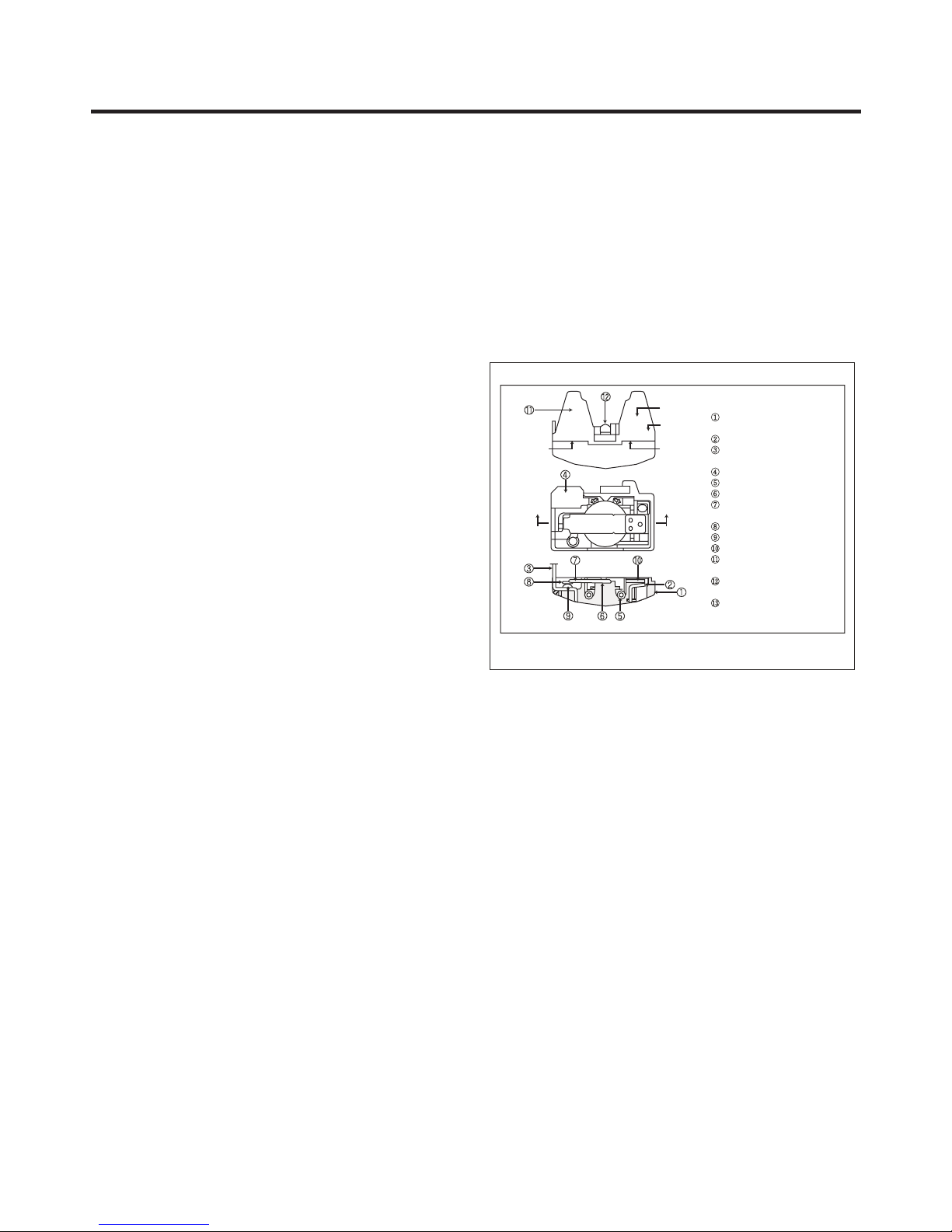
LG LTN16385PL User manual

MODELS
LTN16385PL
CAUTION:
PLEASE READ THE SAFETY PRECAUTIONS OF THIS MANUAL CAREFULLY
BEFORE REPAIRING OR OPERATING THE REFRIGERATOR
REFRIGERATOR
SERVICE MANUAL

CONTENTS
- 2 -
WARNINGS AND SAFETY PRECAUTIONS .................
..................................................................................................................................................................
......................................................................................................................................................
......................................................................................................................................................................
...............................................................................................................................................................................
......................................................................................................................................................................
.............................................................................................................................................................................
Fan and Fan motor ..........................................................................................................................................................
PCB .................................................................................................................................................................................
3.6 Shelves ...........................................................................................................................................................................
3.7 Defrost control .................................................................................................................................................................
3.8 LED ..................................................................................................................................................................................
.....................................................................................................................................................................
.....................................................................................................................................................................
......................................................................................................................................................................
.................................................................................................................................................
...............................................................................................................................................................
..............................................................................................................................
.............................................................................................................................
...................................................................................................................................................................
............................................................................................................................................
...................................................................................................................................................
...........................................................................................................................................................
...............................................................................................................................
...........................................................................................
..........................................................................................................................................................................
7.2 PCB Explanation .............................................................................................................................................................
7.3 Circuit Diagram of Internal Electronic Control (LED)........................................................................................................
8. TROUBLE SHOOTING .........................................................................................................................................................
8.1 Potential Issues ...............................................................................................................................................................
8.2 Trouble shooting (LED)....................................................................................................................................................
9. EXPLODED VIEW .................................................................................................................................................................
...................................................................................................... ......
1. SPECIFICATIONS
2. PARTS IDENTIFICATION
3. DISASSEMBLY
3.1 Doors
3.2 Door switch
3.3 Handle
3.4
3.5
4. ADJUSTMENTS
4.1 Compressor
4.2 PTC-Starter
4.3 OLP (Overload Protector)
5.CIRCUIT DIAGRAM
6. COMPRESSOR TROUBLE SHOOTING
6.1 Compressor and electric components
6.2 PTC and OLP
6.3 Other electrical components
6.4 Service diagnosis chart
6.5 Refrigeration cycle
6.6 General control of refrigeration cycle
7. DESCRIPTION AND FUNCTION OF ELECTRONIC CIRCUIT
7.1 Function
3
5
6
7
7
7
7
7
8
8
8
8
9
9
9
10
11
12
12
13
14
15
16
17
18
18
23
27
29
29
31
52

Extension tube
(load)
Con.
Hen.
Hansen
male
connector
Welding point
Service Tube Extension
Breaking point
Fig. # 1 Fig. # 2
Pressure
Vacuum
pump
gauge
SAFETY PRECAUTIONS
SAFETY AND SERVICE PRECAUTIONS
Fig. # 3
- 3 -
Please read before start your service refrigerator:
1. Disconnect your refrigerator before start the service in
order to prevent electric discharge
2. Check visually there's no a gas leakage or short circuit in
the refrigerator
3. In case of realize tests with the connected refrigerator,
use rubber gloves to prevent any accident
4. If you use any appliance, verify voltage and capacity
regularly
5. Don't touch metallic parts with humid hands, they could
be adhered
6. Make sure there's no water drain to electric or metallic
parts
7. When the freezer door is open and you're checking the
low part, be careful when you lift. You head could be hited.
8. Remove all the glasses, metal u other freely parts when
you tilt the refrigerator.
9.When servicing the evaporator, wear gloves
to prevent injuries from the sharp evaporator
fins. The vacuum process to the system starts as soon as the
pump starts to work. The refrigerator system must be
maintained under vacuum until the low pressure meter
indicate Absolute 0 or -1 atm, -760 mmhg (See Fig. #3) In any
case, the pump must not be working for more than 30
minutes.
In case of leakage and the vacuum couldn't be realized, it's
necessary to apply a small amount of Freon to the system. If
the vacuum isn't achieved (the lower pressure meter doesn't
indicate Absolute 0 or -1 atm, -760 mmhg) turn on the
refrigerator and try to localize the leakage with a leakage
locator. If you identify a welding failure, open the valve to
normalize the interior pressure with the same exterior
pressure before welding. The molten solder could be
suctioned o expelled and block the cycle tubes if the vacuum
system isn't stabilized.
As soon as the vacuum process finish, charge the correct
refrigerant R-134a gram amount in the system. Remember,
each system use an exact R-134a amount with a tolerance of
±5 grams. (See Fig. #4)
It's necessary to realize the welding process with the
opened valve to allow the freely output of gasses from oil.
Use a female connector to join the new tube extension and
the Hansen connector with the vacuum pump. (See Fig. #3)
SERVICE CAUTIONS
Test compressor operation before recharge the refrigerant,
this is important in order to detect immediately failures and
assure compressor motor reliability.
If the failure has been localized, clean possible R-134a
remnants' in the system breaking the end of the compressor
service tube in the thinnest part. As shown in Fig. #1
Change the filter and any other damaged part. Disjoint and
pull away the rest of the service tube. Put a new tube
extension in the Hansen male connector. Weld the new
tube. (See Fig. #2)
Refrigerant Charge to Compressor
Refrigeration
System
Cylinder of R-134a
Fig. # 4

Vacuum pump
Valve must be closed
after achieving a
vacuum
Charging
the cylinder
Refrigerator
system
Refrigerant
Loading tube
Valve should be open
when refilling the gas
Fig. # 5
- 4 -
To know the refrigerant amount that contains and that needs
to be charged to the system, review the graduated scale
cylinder. In example, if we have 750 grams Freon in the
cylinder and we must charge 165 grams to the system, this
amount will be reached when the cylinder indicator shows 585
grams. Remember that the charge indicator shows a lower
lever than real. Do this after select the scale that correspond
to gas pressure indicated in the pressure meter attached in
the column upper part.
Before achieve this operation, make sure that the valve
attached between the vacuum pump and recharge cylinder is
closed in order to keep the Freon to be charged into the
system. (See Fig. #5)
To make R-134a flow to the system, open the valve which is
attached in the cylinder base and is connected to the filling
tube. The Freon gas amount must not be completely charged
in one session because it could block the compressor motor;
therefore, charge 20~30 grams and immediately close the
valve, the pressure increase and the compressor motor start
the suction, this make pressure decrease, open the valve
again and repeat the previous steps until rise the established
amount of R-134a gas for the system. When the system is
under operation, the suction pressure must stabilize between
0.30 and 0.6 atmosphere of pressure.

1. SPECIFICATIONS
- 5 -
Models
Color Platinum Silver 2
Dimensions (in) 31 (W) * 29 (D) * 71 (H)
Net Weight 86Kg
Capacity 16 cuft
Refrigerant R134A
Climate Class Template (N)
Rating 115V /60 Hz
Cooling System Fan Cooling
Temperature Control MICOM Control
Defrosting System Full Automatic / Heater Defrost
Insulation Cyclo Pentanane
Compressor MA53LCCM
Evaporator Fin Tube Type
Condenser Wire
Lubricanting Oil Polyol Ester(POE) 220+_ 10cc
Drier Molecular Sieve XH-7
Capillary Tube ID Ø 0.80
First Defrost 4 Hours
Defrost Cycle 7-50 Hours
Defrosting Device Heater Cord L
Case Material Embo
Door material PET
Handle Type Vertical
Basket Door 4 full
Ice Tray Single
Lamp Yes (LED)
Shelf Glass (3)
Meat Tray No
Egg Tray Yes (1)
Cover TV (Tray Vegetable) Magic Crisper + Plastic
Vegetables Tray Yes (1)
Basket Door 2 Full
Lamp No
Shelf Plastic (1)
FREEZER REFRIGERATOR
Specifications LTN16385PL
GENERAL FEATURES

2. PARTS IDENTIFICATION
- 6 -
A
B
C
D
E
G
K
J
I
H
F
Read this section to familiarize yourself with the parts and features of your new refrigerator.
NOTE: This guide covers different models. Your refrigerator could have some or all of the features and parts listed below.
The location of some of the parts may not correspond to that of your model.
Ice Tray
Freezer Shelf (Plastic)
Temperature Control (Freezer)
Temperature Control (Refrigerator)
Refrigerator Shelves (Glass)
Refrigerator Lamp (LED)
Vegetables Drawer
Keeps fruits and vegetables fresh
Freezer Door Racks
Eggs Tray
Refrigerator Door Rack
Leveling Screws
A
H
B
C
D
E
F
E
E
G
K
I
J

3. DISASSEMBLY
3-1 DOOR
FREEZER DOOR
- 7 -
1. Using the Phillips screwdriver, loose the screw from the top-
hinge cover (a) after this remove it with a flat head screwdriver
(b) (See Fig. 6).
2. Using either a 10 mm or 13/32 in. socket wrench, remove
the three bolts and lift off the top hinge. Set parts aside (See
Fig. 7).
3. Carefully lift up the freezer door. Place the door on a non-
scratching surface. (See Fig.8)
Figure 6
(a)
(b)
Screw
Figure 7
Figure 8
REFRIGERATOR DOOR
1. Loosen and remove the two bolts using the socket wrench
(See Figure 9).
2. Remove the middle hinge bracket (See Figure 10).
3. Carefully lift up the door. Place the door on a non-
scratching surface (See Figure 11).
Figure 9
Middle Hinge
Bracket
Figure 10
Figure 11
3-2 DOOR SWITCH
1. To remove the door switch, remove it with a screwdriver as
shown Figure 12.
2. Disconnect the lead wire from the switch.
Figure 12
3-3. HANDLE DISASSEMBLY
1. Remove the handle deco using a screwdriver to pull it out.
2. With a star screwdriver, remove the screws that holding the
handle with door.
3. Remove the handle, pulling it out for disassembly.

COVER
GRILL DEFROST CONTROL
3-8 LED DISASSEMBLY
12
4
3
- 8 -
3-7 DEFROST CONTROL
The control assembly consists of a transmitter and a
malleable fuse, that with heat opens. The sensor function is
to control the temperature and finish automatically the
defrost, the transmitter is placed on one side of the metal part
of the evaporator. Malleable fuse is a safety device for
preventing overheating of the melt strength at the time of
working.
At a temperature of 77 ° C the fuse opens and stops emitting
heat resistance.
1. Remove the cover from the refrigerator, then remove the
fan grill.
2. Split the connector that is connected to the defrost control
assembly and replace if necessary.
1. Remove the refrigerator .
2. Remove the cover lamp by pressing the bottom to release
the hooks that hold it and then pull to remove.
3. Remove the PCB connector of the LED's.
4. Using a screwdriver, remove the PCB LED's and take it, if
necessary.
5. To reinstall, repeat the same steps but in order opposite.
shelves
3-5 PCB DISASSEMBLY
12
4
3
5
1. Loosen the cover screws.
2. Remove the cover.
3. Disconnect all terminals.
4. Remove the PCB by pressing the hooks to the ends of
cover PCB.
5. Remove and replace the PCB main if necessary.
3-4 FAN AND FAN MOTOR
1. Remove the freezer shelf.
2. Remove the freezer cover lamp, loosening screw fixed to
the ceiling of freezer. (See figure 13).
3. Remove the grill by pulling it out.
4. Remove the cover and remove the fan motor by loosening
two screws.
5. Remove the fan and pull the motor, base and guide fan.
(See figure 14).
Figure 13
Cover Grill
Guide fan
Fan
Fan Motor
Cover Fan
Figure 14
3-6. SHELVES DISASSEMBLY
In order to remove the
refrigerator shelves follow the
next instructions:
1. Take the shelf from the back.
2. Lift it from the bottom by
using the necessary strength
(figure 1).
Shelves
3. Release the locks (figure 2).
4. Slide it towards outside
(figure 3).
NOTE: Make sure that the shelf
is installed in the horizontal
manner. If not secured it can
cause the shelves to fall, which
will cause your stored food to
spill.
Holder
Shelf

PTC
36
S
5
M
SM
TERMINAL
HERMETIC
OLP (OVERLOADED PROTECTOR)
PTC STARTER
RSIR
COMPRESSOR
Figure 20
4-1 COMPRESSOR
4-1-1 Function.
4-2-3 PTC- Circuit Diagram Applied.
- 9 -
4. ADJUSTMENTS
The compressor sucks evaporated gas in low pressure and
lowers the temperature form the evaporator or fridge and
compress this gas at high temperature and high pressure
and passes it on to the condenser.
• According to starting motor method.
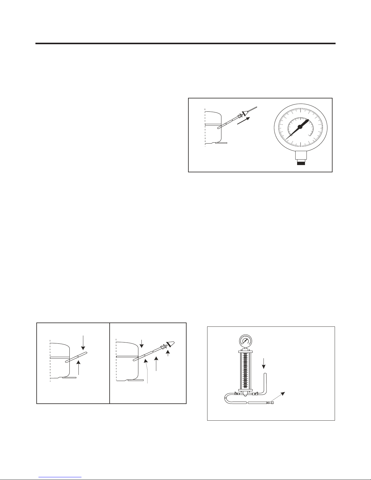
4-1-2 Composition.
Compressor is made up of a system that compresses the
gas, the motor of the compressor and the cover that protects
the device. On the exterior of the compressor is found the
PTC (thermistor) and the OLP (overload protector).
Treat and repair in carefully, because it contains components
of processing accuracy of 1/1000 mm and is sealed dust or
moisture after manufacture.
4-1-3 Notes for use.
(1) Protect your refrigerator of an over voltage or over
current.
(2) Do not hit:
If is forced or hit (dropping or careless treatment), Noise can
originate or have an inefficient operation.
(3) Use appropriate electrical components for the
compressor.
(4) Note for storing the compressor: If the compressor gets
wet during rain and oxidized in the hermetic terminal, may
have a poor operation and cause poor contact.
(5) Ensure that dust, moisture and soldering flux are not
introduced to the compressor during its replacement. Dust,
moisture or flux are introduced to the pipe can cause noise or
clog it.
4-2-1 PTC Composition
(1) The PTC (thermistor) is a semiconductor component that
uses starting ceramic material which is composed of
BaTiO 3.
(2) The higher the temperature, the greater the resistance
value. These characteristics are used for engine starting.
4-2 PTC STARTER
4-2-2 PTC Function
(1) The PTC is attached to the hermetic compressor and is
used for starting the refrigerator compressor.
(2) The compressor of a household refrigerator, uses a motor
of an induction phase, the normal engine operation is started
at the time of starting, the current flows through the auxiliary
winding. Once the boot is completed, the current is cut in the
auxiliary winding because the PTC is connected in series
and this increases its resistance. The characteristics of the
PTC have the above functions. Then, the PTC is used as an
engine starting system.
4-2-4 Restarting the engine and cooling of the PTC
(1) For the restart after power failure during normal operation
of the compressor motor, connect the power cord after 5
minutes for the pressure of the refrigeration cycle to stabilize
and cool the PTC.
(2) During normal operation of the compressor motor, the
elements of PTC generate heat continuously. Hence, if the
PTC is not cooled at some time after power failure, the
engine could not operate again.
4-2-5 Relation between the PTC and OLP
(1) If your power goes out during operation of the
compressor and is reestablished before the PTC has cooled,
(off in a span of 2 minutes or reconnect the power cord due
to a bad connection), the PTC cooling is reached and the
resistance value increases. As a result, the current cannot
flow to the auxiliary winding and the motor cannot start,
because the OLP operates on current flow through the main
winding.
(3) While the OLP repeat the operation on and off about 3 to
5 times, the PTC cools the compressor and the engine
operates normally. If the OLP does not operate when the
PTC is hot compressor motor will overheat causing a short
circuit or even fire. Then, use a flawless OLP.
4-2-6 Note for Using the PTC-Starter
(1) Be careful not to allow over-voltage and over-current.
(2) Do not drop or handle carelessly.
(3) Keep away from any liquid. If liquid such as oil or water
enters the PTC, PTC materials may fail due to breakdown of
their insulating capabilities.
(4) Do not change the PTC at your own convenience. Do not
disassemble the PTC or the mold. Damage to the exterior of
the PTC, the resistance value is altered and can cause
failures on the compressor motor. Use a PTC in good
conditions.

- 10 -
4-3 OLP (OVERLOAD PROTECTOR)
4-3-1 Definition of OLP.
(1) OLP (OVERLOAD PROTECTOR) is attached to the
Compressor and protects the Motor by opening the
circuit to the Motor if the temperature rises and
activating the bimetal spring in the OLP.
(2) When high current flows to the Compressor motor, the
Bimetal works by heating the heater inside the OLP,
and the OLP protects the Motor by cutting off the
current flowing to the Compressor Motor.
4-3-2 OLP Function.
(1) The OLP is attached to the Sealed Compressor used
for the Refrigerator. It prevents the Motor Coil from
being started in the Compressor.
(2) For normal operation of the OLP, do not turn the Adjust
Screw of the OLP in any way.
Part
Customer part
number
Lot code/
date code
330 FBYY -S1 BOX98
12345678
Physical
termination
part number
Electrical
characteristics
part number
No. Name
Base, phenolic
(UL 94 V-0 rated)
Movable arm support, plated steel
Stationary contact support,
plated steel
Heater support, plated steel
Heater, resistance alloy
Disc, thermostatic alloy
Movable arm, spring temper
copper alloy
Contact, movable, silver on copper
Contact, stationary, silver on copper
Slug, plated steel
Cover, polyester
(UL 94 V-0 rated)
Pin connector, plated copper alloy
(To engage 2.33/2.66 mm dia. pin)
Quick-connect terminal, brass,
conforms to UL 310, MEMA
DC-2, DIN 46344
(OVERLOAD PROTECTOR cross section)

- 11 -
5. CIRCUIT DIAGRAM
2
4
3
* P.T.C. START OPTION
6
MA,MC COMP'
5
EG COMP'
CON101
3
CON2
PR
1
BL
45
F,R DOOR
S/W
A
F-FAN
BK:NEGRO/BLACK
YL:AMARILLO/YELLOW
WH:BLANCO/WHITE
5
CON3
3
RD BO
BO
1 2
BN
4
YL
76 8
PR
BN
1
BN
BN
YL
3
C-FAN
M
6 245
BK
M
3
1CON1
2
RD
2
BN
BL
1
BOBO
2
CON4
5
GY
4
3
WH
WH
6
5
C
M
OLP
S
P W B (P C B)
P.T.CSTART
RT-SENSOR
PR:VIOLETA/PURPLE
SB:AZULCIELO/SKY BLUE
BO:NARANJA/BRIGHT ORANGE
A S S E M B LY, M A I N
COMPRESSOR
EARTHPART/
6 7
PK
HEATER, CORD-L
HEATER, PLATE
RD:ROJO/RED
DEF-SENSOR
BL:AZUL/BLUE
GY:GRIS/GREY
R-SENSOR
DOOR S/W
PK:ROSA/PINK
PWB(PCB) ASSEMBLY, DISPLAY
GN:VERDE/GREEN
6
YL
BL
7
BN:CAFE/BROWN
A B
B
PLUGTYPE/
TIPODEENCHUFE
PARTEDETIERRA
GN/YL
WH
SB
YL
BL
FUSE-M2
FUSIBLE-M2
BL
FUSE-M2,FUSE-M3, PTCSTARTOPTION ANDCOMPRESSOREARTHPARTSONCIRCUIT
DIAGRAMARESUBJECTTOCHANGE INDIFFERENTLOCALITIESANDACCORDANCEWITH
THEPLUGTYPE,PLUGEARTH,PLUGWIRESCOLOR,CAPACITOR,F-LEDMODULE, F,RDOORS/W,
ENDIFERENTESLOCALIDADESY DEPENDIENDODELMODELO.
F-LEDMODULE, F,RSWITCHDE LAPUERTA, FUSIBLE-M2, FUSI BLE-M3,PTCSTARTOPTION
YLAS PARTES DETIERRADELCOMPRESOREN
MODEL
TYPE.
ESTEDIAGRAMADECIRCUITOESTANSUJETOSACAMBIO
ELTIPODEENCHUFE, CONECTORDETIERRA, COLORDELOSCABLESDELENCHUFE, CAPACITOR,
FUSE-M1
FUSIBLE-M1
CAPACITOR
RUNNING
F,R SWITCHPUERTA
WH RD
9
C D
C
F-LED
MODULE
R-LED
MODULE
D
63
24 5 8
FUSE-M3
FUSIBLE-M3
BK
BN
2 5
3 6
CIRCUIT DIAGRAM
MEZ46929622

OLP connected?
No voltage
Replace OLP
Reconcect.
YES
YES
Replace compressor
Check OLP
Replace PTC
O.K
Replace OLP
NO
YES
YES
YES
NO
YES
NO
YES
YES
NO
2
2
1
2
5
3
2
4
4
3
5
1
Power Source
3
4
5
Rated voltage ±10%
3
2
NO
NO
NO
NO
6-1 COMPRESSOR AND ELECTRIC COMPONENTS
- 12 -
6. TROUBLESHOOTING
Remove PTC from
compressor (be careful don't
touch the parts loaded),
then measure the voltage
between the blue terminal
(OLP) and terminal 5 or 6 of
PTC.
Voltage applied is not in
range of Rated Voltage
±10%
Advise to customer that
need to use a voltage
regulator.
Check connection
condition.
Check the resistance
between M-C, S-C and
M-S in compressor.
Must be below to
50ohms.
Check resistance of
PTC terminals.
Check
starting state
Check if are using the
correct OLP OLP works during 30
seg. in forced operation
when turned on and off.
Measure minimum voltage
starting after 5 minutes to
balance pressure of the cycle
and cool the PTC.
Components start at the
voltage nominal ±10%

6-2. PTC AND OLP
Replace OLP
YES
NO
Value is ¥
Replace PTC
65
Fig. 1 Fig. 2
?
- 13 -
Normal operation of
compressor is impossible
or poor.
Separate PTC-Starter
from Compressor and
measure resistance
between No. 5 and 6
(RSIR type) or No.4 and 5
from PTC with a tester or
rectifier Wheatstone (see
figure 1).
Separate OLP from
compressor and check
resistance value between
terminals of OLP whit a
tester (see figure 2).
Observation value from
PTC QP2-6R8MD: 6.8W
±20%
Check another
components.
Check another
components.
Resistence value is 0 or
many hundred ohms.

Short
Raise voltage.
Low voltage.
Replace each
component.
Cause
Coil is shorted
Damaged contact
Short
Replace
compressor.
Compressor
coil
Lack of capacity.
a.
Starting devices
Short, open or broken
Poor cooling performance
Not cooling at all
Items shown up are
OK?
b. OLP
c. Compressor coil
d. Wiring harness
Coil open or shorted.
- 14 -
6-3. OTHER ELECTRIC COMPONENTS
Compressor doesn't run. Check if the power flows at
next components:
Poor contact
or shorted.
Poor contact
or shorted.
Compressor runs
poorly. Check a starting voltage.
Check if power flows to
another components.
Replace each
component.
Replace each
component.
Replace each
component.
Replace each
component.
Check if power flows to
compressor coil.
Check rating of OLP.
Poor/ broken / open
contact.
Fan motor doesn't run.
Heavy frost buildup on
EVAPORATOR.
Check rating of OLP.
Check fan motor.
Check current flow in
the following
components:
- Def control assy
Check current flow in
the following
components:
- L-CORD, HEATER
PLATE

- 15 -
6-4. SERVICE DIAGNOSIS CHART
COMPLAINT POINTS TO BE CHECKED REMEDY
Other possible problems:
Check if frost forms in
the freezer.
Check components
of the defrosting
circuit.
Check the
refrigeration system.
Check the
Thermistor.
Not
defrosting
The system
is faulty. Perform sealed
system repair.
Replace the
thermistor.
The operation of
the thermistor is
incorrect.
No Cooling.
Cools poorly.
Foods in the
Refrigerator
are frozen.
Condensartion or ice
forms inside
the unit.
Condensartion forms
in the Exterior Case.
There is abnormal
noise.
Door does not
close well.
Ice and foods
smell unpleasant.
•
• Check if the power switch is set to OFF.
• Check if the fuse of the power switch is shorted.
• Measure the voltage of the power outlet.
• Check if the unit is placed too close to the wall.
• Check if the unit is placed too close to the stove,
gas cooker, or in direct sunlight.
•Is the ambient temperature too high or
•Check if food put in the refrigerator is hot.
•Did you open the door of the unit too often
•
• Check if the control is set to MAX.
•
• Check if food put in the refrigerator is hot.
• Did you open the door of the unit too
• Check if the ambient temperature and humidity
of the surrounding air are high.
•
•
• Are any unnecessary objects placed
• Check if the Tray Drip is not firmly fixed.
• Check if the cover of the compressor enclosure
in the front lower side is taken out.
• Check if the door gasket is dirty with
an item like juice.
•
•
• Check if the inside of the unit is dirty.
•
• The unit smells of plastic.
• Plug into the outlet.
• Set the switch to ON.
• Replace the fuse.
• If the voltage is low, correct the wiring.
• Place the unit about 4 inches (10 cm) from the wall.
• Place the unit away from these heat sources.
• Lower the ambient temperature.
• Put in foods after they have cooled down.
• Don't open the door too often and close
it firmly.
• Place foods in the high-temperature section.
(front part)
• Set the control to MID.
• Seal liquid foods with wrap.
• Put in foods after they have cooled down.
• Don't open the door too often and close
it firmly.
• Wipe moisture with a dry cloth. It will disappear
in low temperature and humidity.
• Fill up the gap.
• Adjust the Leveling Screw, and position the
refrigerator in a firm place.
• Remove the objects.
• Fix the Tray Drip firmly in the original position.
• Place the cover in its original position.
• Clean the door gasket.
• Position in the firm place and level the
Leveling Screw.
• Make sure food stored in shelves does not prevent
the door from closing.
• Clean the inside of the unit.
• Wrap foods that have a strong odor.
• New products smell of plastic, but this
will go away after 1-2 weeks.

Troubleshooting Chart
- 16 -
6-5. REFRIGERATION CYCLE
¥
¥
¥
¥
¥
¥
¥
¥
¥
¥
¥
¥
¥
CAUSE
TEMPERATURE
OF THE
COMPRESSOR
REMARKS
STATE OF
THE UNIT
STATE OF THE
EVAPORATOR
LEAKAGE
CLOGGED BY DUST
DEFECTIVE
COMPRESSION
PARTIAL
LEAKAGE
Freezer
compartment and
refrigerator don’t
cool normally
COMPLETE
LEAKAGE
PARTIAL
CLOG
WHOLE
CLOG
MOISTURE
CLOG
COMPRE-
SSION
NO
COMPRE-
SSION
Freezer
compartment and
refrigerator don’t
cool normally
Freezer
compartment and
refrigerator don’t
cool normally
Freezer
compartment and
refrigerator don’t
cool.
Cooling operation
stops periodically.
Freezer and
refrigerator don’t
cool.
No compressing
operation.
Low flowing sound of
refrigerant is heard and frost
forms in inlet only.
Flowing sound of refrigerant
is not heard and frost isn’t
formed.
Flowing sound of refrigerant
is heard and frost forms in
inlet only.
Flowing sound of refrigerant is
not heard and frost isn’t
formed.
Flowing sound of refrigerant
is not heard and frost melts.
Low flowing sound of
refrigerant is heard and frost
forms in inlet only.
Flowing sound of refrigerant
is not heard and there is no
frost.
A little higher than
ambient
temperature.
- Refrigerant level is low due to a
leak.
- Normal cooling is possible by
restoring the normal amount of
refrigerant and repairing the leak.
Equal to ambient
temperature.
- No discharging of refrigerant.
- Normal cooling is possible by
restoring the normal amount of
refrigerant and repairing the leak.
A little higher than
ambient
temperature.
- Normal discharging of the
refrigerant.
- The capillary tube is faulty.
Equal to ambient
temperature.
- Normal discharging of the
refrigerant.
Lower than ambient
temperature.
- Cooling operation restarts when
heating the inlet of the capillary
tube.
A little higher than
ambient
temperature.
- Low pressure at high side of
compressor due to low
refrigerant level.
Equal to ambient
temperature
- No pressure in the high
pressure part of the compressor.
Leakage Detection
YES
YES
Check if compressor
runs.
Check if frost
forms in
Evaporator.
Observe the discharged
amount of Refrigerant.
Inject refrigerant in compressor
and check cooling operation.
Clogged by dust. Gas leakage.
Faulty
Compressor.
Moisture Clog
Check if oil
leaks.
Frost formed normally
Normal amount
None or too much
(Find the leak and repair it)
Frost formed normally
No frost
or frost forms
in inlet only
Check Compressor
Observe the discharging point of the refrigerant, which may be in the oil discharging part of the compressor and in a hole
in the evaporator.

- 17 -
6-6. GENERAL CONTROL OF REFRIGERATING CYCLE
NO. ITEMS SPECIFICATIONS REMARKS
H ç 0 Chemical composition.
Ag: 30%, Cu: 27%, Zn: 23%, Cd: 20%
Welding temperature: 710~840°
CBcuP2 Chemical composition.
Cu: About 93%
P: 6.8~7.5%
Rest: 0.2%
Welding temperature:
735~840°C
2 FLUX Composition and preparation:
Borax 30%
Borax 35%
Fluoride Kalium: 35%
Water: 4%
Mix ingredients and boil until the liquid
becomes
Prepare only the amount daily. Life time: 1 day.
Closing the container cover to prevent dirt from
mixing with the flux.
Store in a stainless steel container.
3 DRIER ASSEMBLY Assembly the dryer in a period no longer
than 30 minutes after unpacking.
Maintaining the dryer unpacked to a
temperature of 80 ~ 100 ° C.
Not having the dryer on the outside because it
could be damaged by the moisture.
4 VACUUM When calculating loading machine with a
vacuum gauge vacuum gauge should be
around 1 Torr.
If the vacuum cycle is:
-10Torr low pressure and 20 Torr high
pressure, indicating no leak.
The vacuum gauge of the pump must be
less than 0.05 Torr after 5 minutes.
The vacuum gauge should have the same
value as in (2) for 20 minutes.
Use a vacuum gauge without failure.
Perform vacuum operation up to a proper
degree of vacuum (-8 ~ -10 Torr).
If not reached a suitable degree of vacuum, it's
necessary to check the leaks in the cycle and
the adapter connection.
5 AIR DRY &
NITROGEN GAS
Air dry pressure should be between
12~16Kg/cm.
Temperature should be between
20 ~ -70°C.
Keep the pressure between 12~6Kg/cm
when the air be substituted by nitrogen gas.
6 NIPLE & COPLE Check leaks using water with soap.
Replace the coupling in case of leaks.
Check if gas is leaking in connection coupling.
7 PIPE Placing all the cooper connecting tubes in a
clean box and close it to prevent dust and
moisture.
1 Recommended H34 containing 34% Ag in the
service center.
ROD WELDING

7-1. FUNCTION
DESCRIPTION AND FUNCTION OF ELECTRIC CIRCUIT
R0 R1 R2 R3 R4
Temp
Medium
/
Medium
/
Control Low Low
Medium
High Alta
TEMP(ßC)
COMPARTMENT REFRIGERATOR
: ON :OFF
7-1-1 TEMPERATURE CONTROL FUNCTION.
- 18 -
7. ELECTRIC CIRCUIT
1. When the appliance is plugged, temperature is set “medium”. Every time that button is pushed, Lower display is set in
“R2” →“R3” →“R4”→“R0” →“R1”.
2. When power is applied or is restore after blackout, is set automatically “3” against power interruption.
1. This feature is for reducing refrigerator cooling time holding the compressor, fan works a moment. When 'Express
freezing” button is pushed. LED turns on and the compressor keeps working. After 2 hours “Express Freezing” mode will be
deactivated.
2. When defrost mode begins, while "express freezing" is working, the defrost is done. After this, "express freezing"
continues for the time remain.
3. When Button of “Express freezing” is pushed during defrost mode, “Express freezing” begins 7 minutes after that defrost is
done , although “ express freezing “ LED turns on.
4. If an electrical failure appears, while “express freezing” is working, this will be canceled when the energy returns.
5. If “Express freezing” is selected when not out 7 minutes from compressor stopped, the compressor begins to work after
remained periods.
7-1-2 EXPRESS FREEZING
1. When freezer door or refrigerator door is opened. The motor fan stops immediately, when the door is closed, motor fan
starts to work.
7-1-3 FAN CONTROL IN FREEZER ROOM

- 19 -
1. This function activate an alarm every time that door is opened for more than 1 minute
2. After 1 minute with door opened. The alarm sounds 3 times in intervals of 30 sec.
3. The alarm stops sounding when the door is closed or when the function of “door open alarm” is turned off.
This function could be deactivated or activated pushing DOOR ALARM button, the status is shown by a LED.
7-1-4 DOOR OPEN ALARM
SOUND
Close
Open
1 min
30s 30s 30s
Freezer and
Refrigerator
Doors
Less
1 min
Open
Close Close
Door
Alarm
LED
ON
OFF
3 times 3 times 3 times 3 times
The operation defrost start when the total time of compressor achieve 7h.
After to connect the refrigerator (or after the energy interrupted) the defrost will start after at 4h total of work compressor.
When the temperature of defrost sensor achieve 13 °C or more, the defrost was concluded. If after 2h is not achieve the
temperature of 13 °C, the display show a code of error on control display and will finish the defrost.
Starting the normal cycle of cooling (refer to diagnostic mode error, 8.1.4)
When the defrost sensor was damage (the sensor was damage or short circuit) the defrost operation will not make
(after detected the fail is necessary change the sensor).
7-1-5 DEFROST

- 20 -
The operation of electric components such as compressor, the defrost resistence and fans, sequentially starts it is to avoid noise
and damage in the components, the which can result when some components are same time in operation or after finish test.
7-1-6 OPERATION SEQUENCE OF ELECTRIC COMPONENTS
Operating Conditions Sequence of Operation
If the sensor temperature is
When you return to test mode
ALL LOADS 7 min COMP 0.5s FAN
OFF ON ON
When the refrigerator is turned
Connect
0.5s 0.5s
Compressor Fan
Turn on
Connect
0.5s
Defrost
Resistance
10s
0.5s 0.5s
Compressor Fan
On On
25 °C or more (when installed
or after to buy) Turn on
Turn on Turn off
If the sensor defrost
(After a power failure)
temperature is less 25°C
MIN MAX
REF. TEMP. CONTROL
7-1- 7 DIAGNOSTIC MODE ERROR
1. Diagnostic mode error allows to diagnostic service know when a failure is affected to refrigerator performance while in
operation.
2. To press the button for change temperature and case to present a failure the indicators remain the same and the change
temperature will not do it.
3.Ones the problem is solved and goes to work the refrigerator, the error will disappear.
4.The error code is showed in the indicator of temperature (LED’s which adjust the temperature of the refrigerator).
Other manuals for LTN16385PL
3
Table of contents
Other LG Refrigerator manuals
Popular Refrigerator manuals by other brands

Kuppersbusch
Kuppersbusch IKE1660-3 user manual

Amica
Amica AR5222R operating instructions

KitchenAid
KitchenAid KURS24LSBS - ARCHITECT Series II 5.7 cu. Ft.... Dimension Guide

Asko
Asko RFB31231EI Instructions for use

Frigidaire
Frigidaire FRT18JRGD0 Factory parts catalog

Summit
Summit BDR190NACSS Dimensional drawing