manuals.online logo
Brands
  1. Home
  2. •
  3. Brands
  4. •
  5. LG
  6. •
  7. Washer
  8. •
  9. LG FH 96/B8 D Series User manual

LG FH 96/B8 D Series User manual

This manual suits for next models

1

Other LG Washer manuals

LG WT4801CW User manual

LG

LG WT4801CW User manual

LG WM2688H*M User manual

LG

LG WM2688H*M User manual

LG WSC0906WH User manual

LG

LG WSC0906WH User manual

LG WM8100H A Series User manual

LG

LG WM8100H A Series User manual

LG FAV309WNE User manual

LG

LG FAV309WNE User manual

LG WT18WV6 User manual

LG

LG WT18WV6 User manual

LG WM3988HWA Instruction Manual

LG

LG WM3988HWA Instruction Manual

LG WD-12471BDM User manual

LG

LG WD-12471BDM User manual

LG F14A8JDS0H User manual

LG

LG F14A8JDS0H User manual

LG WM8100H A Series User manual

LG

LG WM8100H A Series User manual

LG F0P2CYV2E User manual

LG

LG F0P2CYV2E User manual

LG FWV686WTE User manual

LG

LG FWV686WTE User manual

LG F4J7FH Series User manual

LG

LG F4J7FH Series User manual

LG WD(M)-16220(5)FB User manual

LG

LG WD(M)-16220(5)FB User manual

LG WT1101CW User manual

LG

LG WT1101CW User manual

LG TWC1450S2W User manual

LG

LG TWC1450S2W User manual

LG WM6998HBA User manual

LG

LG WM6998HBA User manual

LG FV1209S5WA User manual

LG

LG FV1209S5WA User manual

LG T9503TEET1 User manual

LG

LG T9503TEET1 User manual

LG WT21VT6HKA User manual

LG

LG WT21VT6HKA User manual

LG P1961RWNT User manual

LG

LG P1961RWNT User manual

LG WT6001H Series User manual

LG

LG WT6001H Series User manual

LG W17600H*A Series User manual

LG

LG W17600H*A Series User manual

LG WD-12270FD User manual

LG

LG WD-12270FD User manual

Popular Washer manuals by other brands

Zanussi ZWF 14080 W user manual

Zanussi

Zanussi ZWF 14080 W user manual

Zanussi FV 825 N Instruction booklet

Zanussi

Zanussi FV 825 N Instruction booklet

Whirlpool 3RGSC9400 Use and care guide

Whirlpool

Whirlpool 3RGSC9400 Use and care guide

Zanussi TJ 1284 H instruction manual

Zanussi

Zanussi TJ 1284 H instruction manual

AEG KO-LAVAMAT 74740 User information

AEG

AEG KO-LAVAMAT 74740 User information

Beko WSRE7512PRA user manual

Beko

Beko WSRE7512PRA user manual

Whirlpool LA5OOOXP Use and care guide

Whirlpool

Whirlpool LA5OOOXP Use and care guide

Miele PW 6207 operating instructions

Miele

Miele PW 6207 operating instructions

GE GE Profile WWSE3160AAA Specifications

GE

GE GE Profile WWSE3160AAA Specifications

Bush WMNB712EB instruction manual

Bush

Bush WMNB712EB instruction manual

ALLIANCE UW60AV Information manual

ALLIANCE

ALLIANCE UW60AV Information manual

Bosch WAN280H3 User manual and installation instructions

Bosch

Bosch WAN280H3 User manual and installation instructions

Maytag MAT15MNAW installation instructions

Maytag

Maytag MAT15MNAW installation instructions

Indesit IWC 61481 Instructions for use

Indesit

Indesit IWC 61481 Instructions for use

Electrolux EWF12843 user manual

Electrolux

Electrolux EWF12843 user manual

Indesit WIN 70 Instructions for use

Indesit

Indesit WIN 70 Instructions for use

Whirlpool Cabrio WTW6400SW2 quick start guide

Whirlpool

Whirlpool Cabrio WTW6400SW2 quick start guide

Bosch WGB25400BY User manual and installation instructions

Bosch

Bosch WGB25400BY User manual and installation instructions

manuals.online logo
manuals.online logoBrands
  • About & Mission
  • Contact us
  • Privacy Policy
  • Terms and Conditions

Copyright 2025 Manuals.Online. All Rights Reserved.

WASHING MACHINE
SERVICE MANUAL
CAUTION
READ THIS MANUAL CAREFUL LY TO DIAGNOSE TROUBLE
CORRECT LY BEFORE OFFERING SE RVICE.
MODEL : FH*96/B8(T/Q)D(1~9)
website : http://biz.lgservice.com
e-mail : http://LGEservice.com/techsup.html
2
CONTENTS
1. SPECIFICATIONS ............................................................................................................................. 3
2. FEATURES & TECHNICAL EXPLANATION ..................................................................................... 4
3. PARTS IDENTIFICATION ................................................................................................................. 6
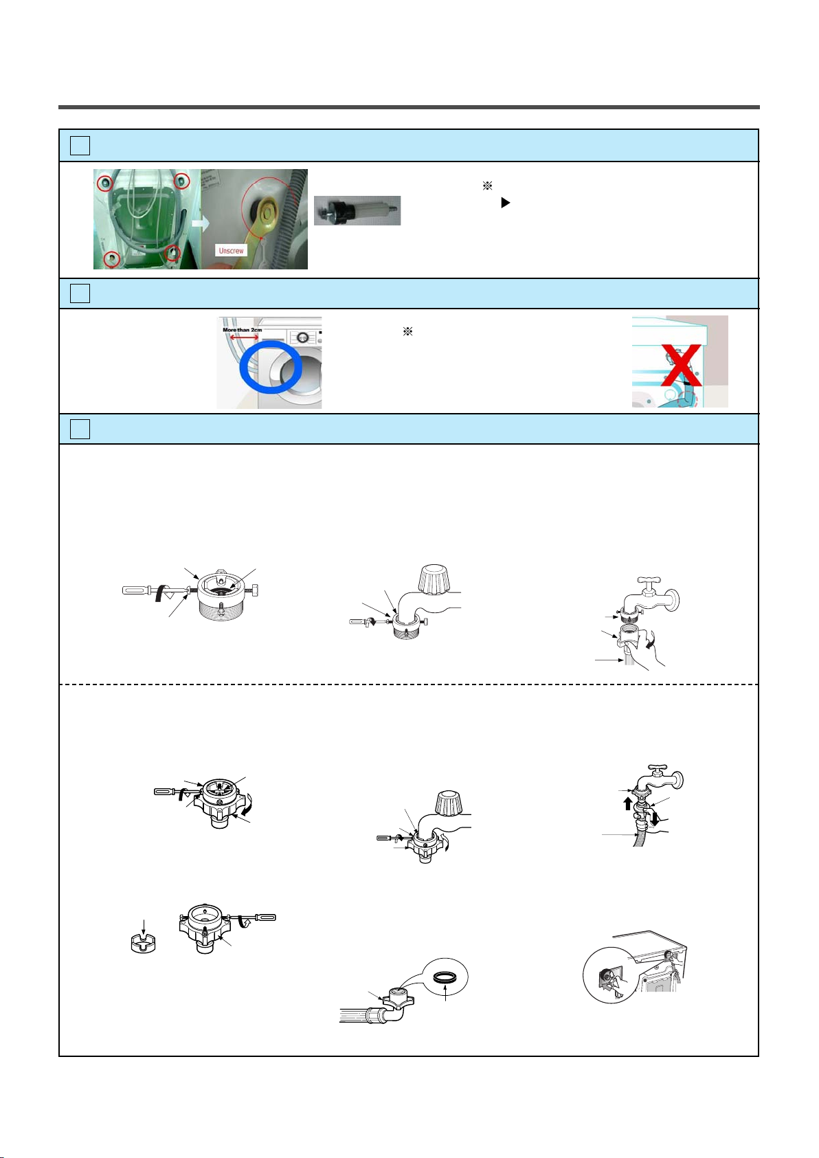
4. INSTALLATION .................................................................................................................................. 7
5. OPERATION ...................................................................................................................
.........................
................ 12
5-1. F**96(T/Q)D(1~9), F**B8(T/Q)D(1~9), WD14022D6, WD12021D6 ............. 12
6. WIRING DIAGRAM / PCB LAYOUT / PROGRAM CHART ............................................................ 16
7. TROUBLESHOOTING......................................................................................................................17
7-1.BEFORE PREFORMING SERVICE ......................................................................................... 17
7-2.LOAD TEST MODE .................................................................................................................. 17
7-3.HOW TO KNOW THE WATER LEVEL FREQUENCY ............................................................. 17
7-4.ERROR DISPLAY ..................................................................................................................... 18
7-5.TROUBLESHOOTING WITH ERROR ..................................................................................... 19
• IE (Water Inlet Error) .............................................................................................................. 19
• UE (Unbalanced Error) ........................................................................................................... 20
• OE (Water Outlet Error) .......................................................................................................... 21
• FE (Flow over Error) ............................................................................................................... 23
• PE (Pressure Sensor S/W Error) ............................................................................................ 24
• DE (Door open Error) ............................................................................................................. 25
• tE (Thermistor (Heating) Error) ............................................................................................... 26
• LE (Motor Lock Error) ............................................................................................................. 27
8. TROUBLESHOOTING WITHOUT ERROR CODES ...................................................................... 29
• PF (Power Failure or no power) ............................................................................................. 29
• Vibation & Noise in spin ......................................................................................................... 30
• Detergent & Softener does not flow in .................................................................................... 31
• Water Leak ............................................................................................................................. 32
9. DISASSEMBLY INSTRUCTIONS ................................................................................................... 34
10. EXPLODED VIEW ......................................................................................................................... 41
3
1.SPECIFIC ATION
POWER SUPP LY
PRODUCT WEIGHT
OPER ATION WATER PRESSURE
CONTROL TYPE
WASH CAPACITY
DIMENSION
DOOR SWITCH TYPE
WATER LEVEL
DELAY FINISH TIME
SENSING OF THE LAUND RY AMOUNT
FUZZY LOGIC
DISPLAY OF THE REMAINING TIME
ERROR DIAGNOSIS
POWER AU TO OFF
CHILD LOCK
AUTO RESTART
ELECTRICITY
CONSUMPTION
WASHING
SPIN (1400rpm)
DRAIN MOTOR
WASH HEATER
REVOLUTION
SPEED
WASH
SPIN
FH2** (T/Q)D(1~9) No Spin~1200 rpm
FH4** (T/Q)D(1~9) No Spin~1400 rpm
50rpm
100-800kPa (1.0-8.0kgf/
㎠)
Electronic
Cotton 8kg (Max.)
600mm(W)x550mm(D)x850mm(H)
Bi-Metal type
9steps (by sensor)
From 3 hours to 19 hours
Available
Available
Available
10 items
Available
Available
Available
135W
530W
30W
2000W
220-240V~, 50Hz
64kg
ITEM
Refer to 1 page
2-1. FEATURES
Anti Crease function
With the alternate rotation of the drum, creasing in the laundry is
minimized.
More economical by Fuzzy Logic System
FUZZY Logic System detects the amount of load and water
temperature, and then determines the optimum water level and
washing time to minimize energy and water consumption.
Child-Lock
The Child-Lock system has been developed to prevent children
from pressing any button (except Power button) to change the
programme during operation.
Low noise speed control system
By sensing the amount of load and balance, this system
automatically distributes load evenly to minimize the spinning
noise level.
Direct Drive System
The advanced Brushless DC motor rotates the drum directly
without a belt and a pulley.
Built-in heater
Internal heater automatically heats the water to the best
temperature on selected cycles.
4
2. FEATURES & TECHNICAL EXPLANATION
5
2-2. DETERMINE WASHING TIME BY FUZZY LOGIC
To get the best washing performance optimal time is determined by sensing of water temperature,
selected washing temperature and laundry amount.
2-3. WATER LEVEL CONTROL
This model uses a pressure sensor to determine the water level in the tub.
When the preset water level reached, water supply is stopped and the program proceeds.
Water needs to be below a preset level before spining will proceed.
water
temperature
washing time
rinse time
the best
washing
performance
spin rhythm, time
laundry
amount
FUZZY
LOGIC
selected
washing
temperature
SENSING EFFECT
PROCESSING
DETERMINATION
2-4. THE DOOR CAN NOT BE OPENED
While program is operating.
While Door Lock light turns on.
6
3. PARTS IDENTIFICATION
Drawer
Door
Adjustable Feet
Power Plug
Control Panel
Drain Pump Filter
Drain Plug
Lower cover cap
If the supply cord is
damaged, it must be
replaced by the
manufacturer or its
service agents or a
similarly qualified
person in order to
avoid a hazard.
ACCESSORIES
Inlet hose(1EA) Option : Hot / Cold(2EA) Spanner
Drum
Lower cover
(For datergent and
fabric softener)
7
4. INSTALLATION
INSTALLATION
The appliance should be installed as follows.
Check the conditions of installation area.
1. Check level ground.
On raised foundations or upper level homes, the vibrations can be caused by the type of flooring.
It may be necessary to move the machine to a different area in the home or have the floor
reinforced to properly support the operation of the unit.
2. Check humidity or any foreign objects under the feet.
Clean the floor, and there should not be any foreign objects under the feet.
If the unit has foreign objects underneath the feet, this will prevent the unit from being leveled properly
and will cause vibrations and slipping.
Remove any foreign objects, if any from underneath the machine and level unit properly.
See below for examples of foreign objects.
1
Open the box and check appliance condition.
2
horizontal
Capet Paper Laminated
paper
Washer
Base Packing
Wrench
This leveling (or spanner) wrench must
be used to remove the shipping bolts
and level the unit. This should be kept
for future use.
Packing Support
Purchased
stopper
8
Use spanner to remove transit bolts.
3
Confirm the distance between the appliance and the wall.
4
The tap connection and hose connection must be parallel.
5
Without removal of transit bolts
Spin noise and shaking.
X 4 EA
Transit bolts
More than 2cm If the distance is less than 2cm,
the water supply hose will
kink or fold.
1. Normal Tap without thread & screw type inlet hose.
1. Unscrew the fixing screw to
attach the tap.
2. Push the connector up till the
rubber packing is in tight contact
with the tap. Then tighten the 4
screws.
3. Push the water supply hose
vertically upwards so that the
rubber packing within in the hose
can adhere completely to the tap
and then tighten it by screwing it
to the right.
1. Untighten the upper connector
screw.
2. Push the upper connector up
till the rubber packing is in
tight contact with the tap. Then
tighten the 4 screws.
3. Connect the water supply hose
to the middle connector, pushing
the plate down.
•In case the diameter of the tap
is large remove the guide plate. •Turn the middle connector not to
have water leaked.
•Make sure that the rubber seal is
inside the hose connector.
•To separate the water supply
hose from the middle connector
shut off the tap.
Then pull the inlet hose down,
pushing the plate down.
•Make sure that there are no
kinks in the hose and that it is
not crushed.
2. Normal Tap without thread & one touch type inlet hose (Single inlet models)
Upper
Connector
Fixing screw
Guide plate
Connector
Rubber packing
Upper
Connector
Rubber packing
Upper
Connector Plate
Water supply
hose
Rubber seal
Hose connector
Upper
Connector
Middle
connector
Rubber
packing
Upper
Connector
Fixing screw
Middle
connector
Rubber
packing
Upper
Connector
Plate
Water supply
hose
9
Connect Drain Hose.
6
Connect power plug.
7
If the drain hose is not installed properly, the unit will not drain properly.
This allows water to back flow into the unit which can cause odors.
Refer to Owner Manual for proper drain hose installation.
The odor could also be coming from the home’s drain to which the drain hose is attached.
In this type of drain hose installation, the odor could be coming from the standpipe.
This odor can come up the drain hose and into the unit.
Pour a cup or two of bleach or vinegar down the home drain
and let it sit for 24 hours before running another cycle.
This will help eliminate odor from the home drain.
If a cycle is started too soon after doing this, it will not help the issue.
Connect the power plug to the wall outlet. Avoid connecting several electric devices,
it may be the cause of a fire.
about 100 cm
about 145 cm
about 105 cm
Laundry tub
Max. 100cm
min. 60cm
Max. 100cm
min. 60cm
Retainer
Tie
strap
Hose
min. 60 cm
max. 100 cm
10
Check the horizontality with a level (Gage).
8
1 Step
If washing machine legs are loose or not screwed, then screw up with the spanner wrench.
Using the level, level the washing machine from front to back and side to side.
2 Step
Using the spanner wrench to adjust leg for horizontality and try for Diagonal test.
3 Step
Perform a Rinse and Spin with some clothing in the machine.
To do this, put 2~3kg of clothing in the unit, power on the unit, press the Rinse and Spin
button, and then start. When the unit reaches the spin cycle, watch for vibrations.
If the unit is vibrating, make small adjustments to the leg until they subside. (Try 2Step again)
4 Step
Tighten the lock nut against the base of the machine to lock the position leg.
Lower the foot until there is no gap between floor and foot.
And only use adjustment rubber when difference at the leg adjustment is more than 10mm.
Place your right hand on the back, right corner and your left hand on the front,
left corner of the unit, then attempt to rock the unit from corner to corner.
Then, move your right hand to the front, right side and your left hand to the
back, left corner and attempt to rock the unit from corner to corner.
If the unit is level, it will not rock. However, if the unit is not level, it will rock.
If the unit rocks, it will be necessary to adjust the leveling feet of the unit.
Adjust the foot under the hand that is on the front of the machine.
How to perform a diagonal test:
A level
Higher
Tighten
Adjustable feet
Diagonal test
Tighten
Adjustable feet
Higher
Tighten
Adjustable feet
Lower Lock nut
10mm
Adjustable bolt
Tighen the lock nut
4620ER3001B
(Gray)
for Wooden floors
Rubber Cup
4620ER3001A
(Black)
for Tile floors