Libec QH1 User manual

QH1
QH3

安全のための注意事項を守らない場合、けがをすることがあります。この取扱説明書は必ずお読みください。事故を防ぐための重要な注意事項と製品の取り扱い方法を記載しております。十分理解のうえ、安全に正しくお使いください。お読みになったあとは分かりやすい場所に必ず保管して、いつでも読み返すことができるようにしておいてください。本製品は安全を充分考慮して設計されておりますが、誤った使い方をすると破損や搭載カメラの落下により人にけがを負わせることがあります。●使用の前にこの「安全上のご注意」をよくお読みのうえ、正しくお使いください。●ここに示した注意事項は、安全に関する重要な内容を記載しておりますので必ず守ってください。
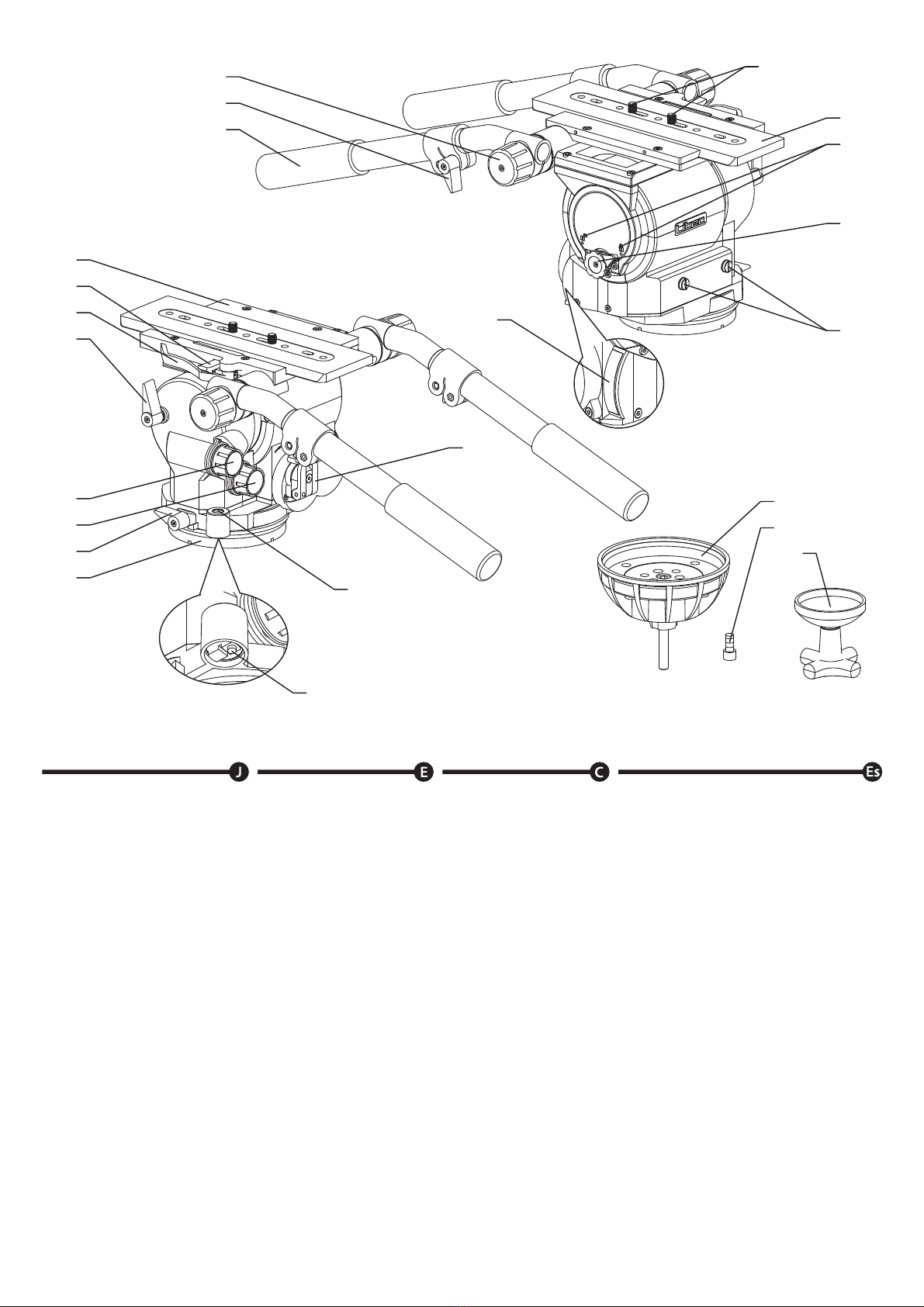
次の注意事項を守らない場合、けがをすることがあります。●重量制限を守る:取り付けられるカメラ等の重量は
QH1:40kg以下、QH3:69kg
以下です。搭載荷重の制限を超えるとヘッドや脚に過負荷がかかり、破損やカメラの落下を招き人にけがを負わせる原因となることがあります。●バランス調整や機材から離れる時は、安全の為に水平ロックツマミを有効にしてください。●各ロックツマミやレバー及び脚ロックレバー、カメラネジなどの締め付け具は確実に締め付けてロックする:締め付けが弱いと、ずれたり外れたりして、カメラの破損や人にけがを負わせる原因となることがあります。●脚は確実に開いてからカメラを取り付ける:
開脚が不充分のままカメラを取り付けると、転倒してカメラの破損や人にけがを負わせる原因となることがあります。
●分解や改造はしない:分解や改造をすることにより人にけがを負わせたり、故障の原因となることがあります。故障したら使用せず、販売店または弊社サービス担当にご相談ください。
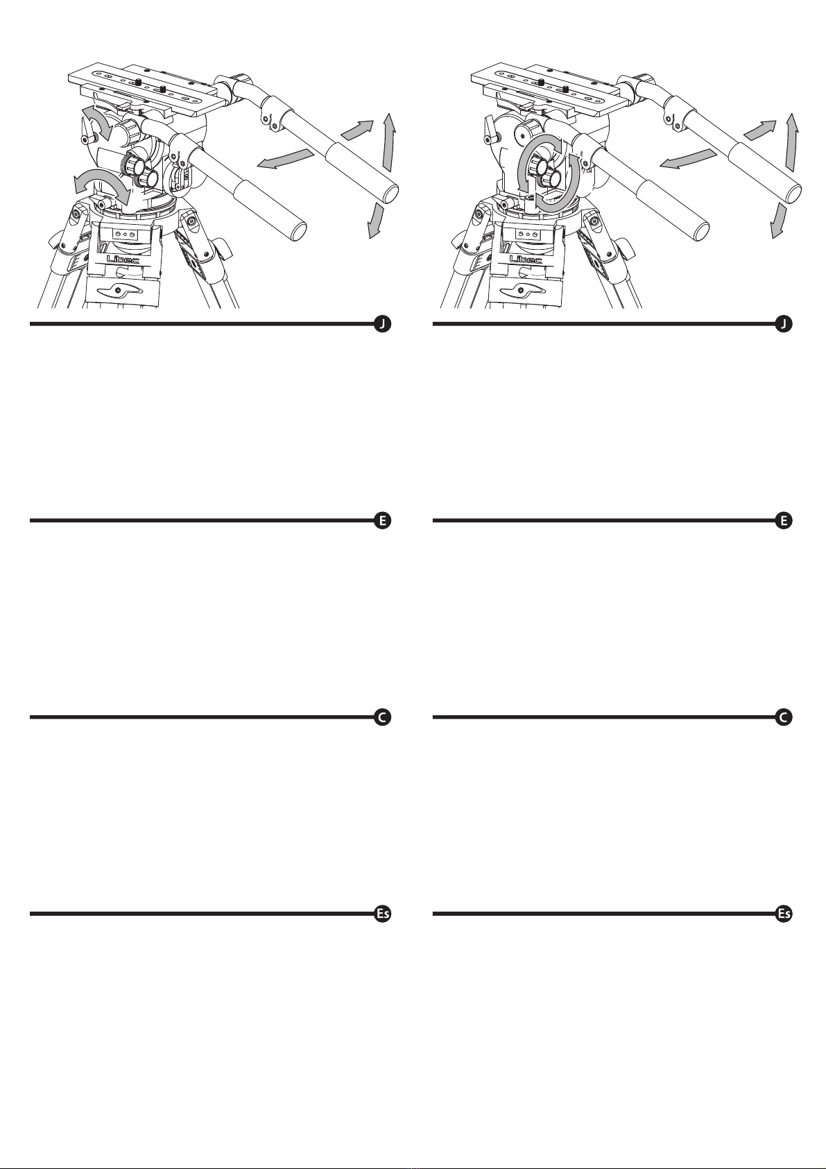
1.使い終わったら、必ずカメラをヘッドから取りはずしてください。カメラ等を付けたまま持ち運ばないでください。2.パンハンドルを持って運ばないでください。3.ティルティング、パンニング操作はティルトロックツマミ、パンロックツマミを確実にゆるめて行ってください。4.ヘッドを長時間使用しない時は、カウンターバランス調整ツマミをゆるめた状態で保管してください。If not installed and used in accordance with this manual, this equipment may
cause harm.
Operating procedures and cautions were written to prevent accident from
occurring.
For your own safety, read and follow these instructions before operating it. With
adequate understanding, proper and safe operations will be achieved. Please
retain this manual for future references. This product has been designed with
consideration for your safety. However, improper operations may cause camera
equipment to collapse, which may result in damage to equipment and/or cause
personal injury.
・Please read all the cautions and procedures before use.
・Please follow all the written cautions and safety contents.
Caution
Injury may happen if the guidelines are not followed.
・Do not exceed the maximum capacity:The maximum load capacity for QH1:40kg/88.2lb,QH3:69kg/152.1lb.
Exceeding the load capacity may cause damage to equipment and/or may cause
personal injury.
・When balancing the camera or leaving the equipment unattended,
please activate the Center Tilt Lock for safety.
・Firmly tighten all locks, screws and clamp:
Failing to do so may cause damage to the camera or injury to others.
・Mounting of camera on a proper positioned tripod:
Mounting the camera on a improperly setup tripod may results in damages
and/or personal injuries.
・Do not dismantle or modify:Dismantling and modifying the equipment may inflict injury to self or others,
and may lead to defects.
Do not operate when the equipment is out of order; contact the dealer or our
customer service for repair. ྲн৲➗ᵜᤷইᆹ㻵઼֯⭘ˈሶ㜭䙐ᡀᦏՔDŽѪҶᛘⲴᆹޘˈ䈧৲➗ԕл䈤᰾DŽᵜ֯⭘䈤᰾Җ䇠䖭ᴹ亴䱢һ᭵⭏Ⲵ䟽㾱⌘һ亩ԕ৺ӗ૱Ⲵ֯⭘䈤᰾DŽ䈧ݵ࠶⨶䀓Ⲵสкˈᆹޘ↓⺞֯⭘DŽ䈕䇮༷ࡽˈ䈧Ԅ㓶䰵䈫ᵜ䈤᰾ᒦ؍ᆈᆳԕׯሶᶕ֯⭘৲㘳DŽᵜӗ૱Ⲵ䇮䇑ᐢ㘳㲁ࡠ֯⭘ᆹޘᙗDŽնᱟн↓⺞Ⲵሶ䙐ᡀᩴۿᵪӾй㝊к䏼㩭ˈԕ㠤֯䇮༷ᡆӪઈࡠᦏՔDŽȘֵ⭞ᵢӝࢃ䈭䇚ⵕ䰻䈱ᆿޞ⌞ᝅӁ亯ȾȘ൞↚ᡶ⽰⌞ᝅӁ亯䇦ᖋީᆿޞⲺ䠃㾷ᇯθ䈭ࣗᗻ䚫ᆾȾ⌞ᝅྲн৲➗ԕл䈤᰾ᆹ㻵઼֯⭘ˈሶ㜭䙐ᡀᦏՔDŽȘ䈭䎻䗽ᴶཝᢵ䠃φ҈䖭ᩴۿᵪ㌫㔏Ⲵ䟽䟿䲀ࡦѪ˖4+˖NJԕлˈ4+˖NJԕлDŽ䎵䗷ᴰབྷ䟽ሶᦏՔ䇮༷ᒦ⭏н亴⍻ⲴཆDŽȘ䈹᮪ᢎᶵࢃփ㖤ᰬθᡌᬃ֒㘻㾷⿱ᔶಞᶆᰬθᓊሼإԦѣᗹ䬷ṉ䬷рȾȘ㍝ര䬷䫤Ƚ᩺܅ᵰരᇐ㷰䪿Ƚ㷰ѓૂᢁφྲ䬱䫞⋑ᴹ㍗Ⲵ䈍ˈᩴۿᵪᴹ㜭ඐ㩭ᦏˈᒦ㜭ሬ㠤ӪઈՔDŽȘ䈭ݾ⺤䇚п㝐Ѱどᇐ⣬ᘷθ߃ᆿ㻻᩺܅ᵰφྲй㝊ᆹ㻵н↓⺞ᡆᵚ᤹↔䈤᰾Җᆹ㻵ˈሶ㜭ሬ㠤ಘᶀᦏՔᡆӪઈՔDŽȘ䈭䳅ᝅমᡌ᭯㻻φ䈧䲿নᡆ᭩㻵ˈഐѪ䘉ሶ㜭ሬ㠤ಘᶀᦏՔᡆӪઈՔDŽ⭏᭵䳌ᰦ䈧֯⭘ᒦ㚄㌫䬰୶DŽֵ⭞ࢃ䆜ᜋᩢ䘆䗽ぁѣθ᩺܅ᵰᗻ亱〱䲚Ⱦ䈭ᨗжᢁ䘑㺂ᩢ䘆θሼ䙖ᡆ㝐ᦕ՚Ⱦᖉ䘑㺂إԦᡌ≪ᒩࣞ֒ԛ䘑㺂᩺ᖧᰬθ䈭ᇂޞ䠀᭴രᇐ䬷䫤Ⱦ䮵ᰬ䰪уֵ⭞Ӈᰬθ䈭ሼࣞᘷᒩ㺗䈹᮪㠩ᴶᶴⲺ⣬ᘷȾSi no se instala y utiliza de acuerdo con este manual, este equipo puede causar
daños.
Los procedimientos de operación y las precauciones fueron escritas para prevenir
accidentes.
Por su propia seguridad, lea y siga estas instrucciones antes de operarlo. Con la
comprensión adecuada, se lograrán operaciones adecuadas y seguras. Conserve
este manual para futuras referencias. Este producto ha sido diseñado teniendo en
cuenta su seguridad. Sin embargo, las operaciones incorrectas pueden provocar el
colapso del equipo de la cámara, lo que puede provocar daños en el equipo y / o
lesiones personales.
・Antes de utilizar el equipo, lea por favor las siguientes notas de seguridad.
・Por favor, siga todas las precauciones escritas y contenidos de seguridad.
Precauci n
Este equipo puede causar lesiones si no se instala o usa de la manera en que se
especifican en las instrucciones.
・No exceder la capacidad máxima:La capacidad de carga máxima de QH1: 40kg / 88.2lb, QH3: 69kg / 152.1lb.
Superar la capacidad de carga puede causar daños al equipo y / o lesiones
personales.
・Al balancear la cámara o dejar el equipo desatendido, active el seguro de
inclinación central para mayor seguridad.
・Apriete firmemente todos los seguros, tornillos y abrazaderas:
Si no lo hace puede causar daños a la cámara y / o lesiones a otras personas.
・Montaje de la cámara en un trípode colocado correctamente:
Montar la cámara en un trípode mal instalado puede causar daños y / o lesiones
personales.
・No desarme o modifique este equipo:El desmontaje y la modificación del equipo pueden causar lesiones a sí mismos
oa otros, y pueden provocar defectos.
No operar cuando el equipo está fuera de servicio; Póngase en contacto con el
distribuidor o con nuestro servicio de atención al cliente para su reparación.
Precauciones antes de su uso
1. Retire la cámara de la cabeza del trípode. No lleve la cabeza del trípode
con la cámara instalada.
2. No sujete el cabezal por el maneral durante el traslado.
3. Cuando se inclina o se desplaza, es importante aflojar completamente el
seguro de la inclinación o paneo.
4. Cuando la cabeza no esté en uso por un período de tiempo, ajuste el
contrapeso al mínimo para el almacenamiento.
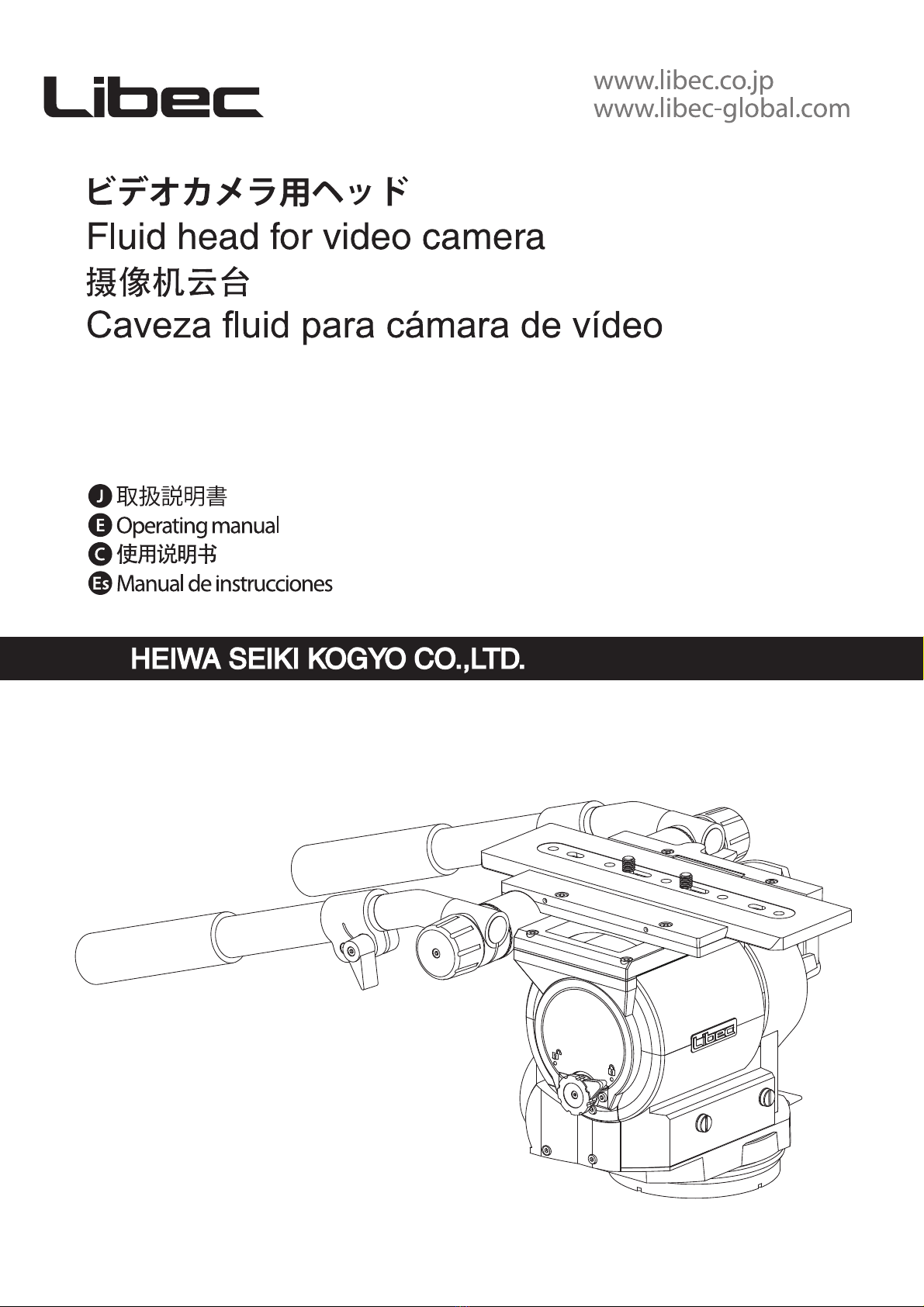
このたびは本製品をお買い上げいただきありがとうございます。安全上のご注意使用上のご注意
Precaution before use
1. Please remove the camera from the tripod head. Do not carry the tripod
head with the camera attached.
2. Do not hold the head by the pan handle during relocation.
3. When tilting or panning, it is important to loosen the tilt or pan lock
completely.
4. When the head is not in use for a period of time, set the counterbalance
to the minimum for storage.
2

A: 各部の名称A: Part name A: 䜞Ԭ〦A: Nombre de la pieza
1
2
3
4
5
6
7
8
9
10
11
12
13
14
15
16
17
18
19
20
21
22
23
1
2
3
4
5
6
7
8
9
10
11
12
13
14
15
16
17
18
19
20
21
22
23
1
2
3
4
5
6
7
8
9
10
11
12
13
14
15
16
17
18
19
20
21
22
23
1
2
3
4
5
6
7
8
9
10
11
12
13
14
15
16
17
18
19
20
21
22
23
ヘッドプレートロックフックプレートロックレバーティルトロックツマミティルトトルク切替ツマミパントルク切替ツマミパンロックツマミフラットベース水準器照明スイッチ水準器カウンターバランス調整ツマミメーターパンハンドル(L、R)パンハンドル伸縮ロックツマミパンハンドルロックツマミカメラネジスライドプレート水平ロックアイコン水平ロックツマミスペアカメラネジネジ穴(3/8-16 UNC)ボールレベラーボールレベラー取付けネジ3/8
ボールレベラー締付ハンドルHead
Slide plate safety release lock
Quick release mechanism
Tilt lock
Tilt drag control
Pan drag control
Pan lock
Flat base
Level illumination switch
Bubble level
Counterbalance knob
Counterbalance meter
Pan handle (L , R)
Telescopic clamp
Pan handle clamp
Camera screw
Slide plate
Center Tilt Lock Icons
Center Tilt Lock
Spare camera screw
Screw hole (3/8-16 UNC)
Ball leveler
Ball leveler fixing screw 3/8"
Bowl clamp
Cabeza
Cierre de seguridad para placa deslizante
Mecanismo de liberación rápida
Seguro de inclinación
Control de arrastre de inclinación
Control de arrastre de paneo
Seguro de paneo
Base plana
Interruptor de iluminación de nivel
Nibel de burbujas
Perilla del seguro de contorapeso
Medido de contrabalance
Abrazadera de deslizamiento (L , R)
Sujetadoe de la extension
Abrazadera de maneral
Perilla del seguro de la placa
Placa deslizante
Iconos de seguro de inclinación central
Seguro de inclinación central
Tornillo de repuesto de la cámara
Orificio de tornillo (3 / 8-16 UNC)
Nivelador de bola
Tornillo de fijación 3/8 para nivelador de bola
Manija de fijación de nivelador de bola
Ӂ━ᶯ䬱䫙━ᶯ䬱ᵶ؟Ԡ䬱؟Ԡ䱫ቬẓս䫞≤ᒣ䬱≤ᒣ䱫ቬẓս䫞ᒣᓅᓅᓗ≤ᒣ⌑➗᰾ᔰޣ≤ᒣ⌑ࣘᘱᒣ㜭䈳ᮤ䫞ࣘᘱᒣ㜭ᕪᓖ䇑ᐖˈ᭦㕙പᇊ䬱പᇊ䬱ᩴۿᵪപᇊ㷪эᢈᶯ؟Ԡѝᗳ䬱ḷᘇ؟Ԡѝᗳ䬱ṃ༷⭘ᩴۿᵪപᇊ㷪э㷪эᆄ81&⨳⻇≤ᒣಘ㤡㷪э⨳⻇≤ᒣಘ䈳ᮤᢺA
1
2
3
4
5
6
7
8
20
21
22
23
11
9
12
3
14
13
15
10
16
17
18
19

B: フラットベース仕様のヘッドを取り付ける4本のボールレベラー取付けネジ3/8で確実に固定してください。●P1000にセットする際は、P1000の取扱説明書にしたがってください。フラットベース仕様からボールレベラー仕様に変更するスライドプレートをはずし、フラットベースが上になるようにヘッドを置きます。ボールレベラーをフラットベースに被せて、各穴を合わせます。六角レンチを使用し、ボールレベラー取付けネジ3/8で確実に固定します。(4カ所)※動作時のガタ等に影響しますので、4箇所とも確実に締めて固定してください。ボールレベラー仕様のヘッドを取り付けるヘッドのボールレベラー締付ハンドルをゆるめて取りはずします。ヘッドを三脚に取り付けます。ヘッドの水平を調整する水準器の気泡が円の中に入るように、ヘッドを動かします。※水準器照明スイッチを押すと照明が10〜15秒間点灯します。また点灯中に水準器照明スイッチを押すと照明が消灯します。ボールレベラー締付ハンドルを確実にしめて固定してください。使いやすい位置と長さにパンハンドルを調整するゆるめる位置を調整する長さを調整するロックする1
2
3
4
5
6
7
8
9
10
11
12 機材にヘッドを取り付けるB:
1
2
3
4
5
6
7
8
9
10
11
12
Placing the tripod head.
B:
1
2
3
4
5
6
7
8
9
10
11
12 ሼӇᆿ㻻㠩᭥ಞᶆрB:
1
2
3
4
5
6
7
8
9
10
11
12
Colocando la cabeza del trípode.
B
Attaching a flat-base head
Secure the head with 4x 3/8" screws.
・Refer to the P1000 operation manual when attaching the head onto the
P1000.
Changing the flat-base configuration to a ball-base configuration
Remove the slide plate and place the head with the flat-base facing up.
Place the ball leveler on top of the flat base and match each hole.
Use the hexagon wrench to firmly attach the 4x 3/8" screws.
※Make sure the screws are securely fastened or they may become loose
during usage.
Mounting the ball-base configuration head
Loosen the bowl clamp and remove it from the head.
Set the head on to the tripod.
Leveling the head
Hold the head, look at the bubble level and glide the ball leveler while
keeping the bubble at the center.
※Press the level illumination switch and bubble level will light up for
about 10 to 15 sec, LED will cut off after this period or by pressing the
switch again.
Firmly tighten the bowl clamp.
Adjusting the pan handle to the preferred length
Loosen the telescopic clamp.
Adjust the position.
Adjust the length.
Lock the telescopic clamp.
ᆿ㻻ᒩᓋӇሶഋ㤡㷪э⺞ᇎപᇊDŽƽᆹ㻵Ҿ3䱽ᰦˈ䈧৲䰵3䱽֯⭘䈤᰾ҖDŽሼӇԄᒩᓋṭᕅ᭯㻻Ѱ⨹⻍ṭᕅሶᢈᶯনˈᒦሶӁᒣᓅᓅᓗᵍк᭮㖞DŽሶ⨳⻇≤ᒣಘⴆҾᒣᓅᓅᓗѻкˈᒦሩ߶㷪эᆄDŽ֯⭘ޝ䀂ᢣሶഋ㤡㷪э⺞ᇎ䬱㍗DŽĆྲ㷪э⋑ᴹ⺞ᇎ䬱㍗ˈሶ൘ᰦӗ⭏ᱳࣘDŽᆿ㻻⨹⻍Ӈሶ⨳⻇≤ᒣಘ䈳ᮤᢺ䖜ᶮᒦлDŽሶӁᆹ㻵㠣й㝊кDŽ䈹᮪ӇⲺ≪ᒩ䈳ᮤӁս㖞ˈ䇙≤ᒣ⌑ᖃѝⲴ≄⌑㜭䘋ޕ≤ᒣ⌑ⲴശസDŽĆ᤹≤ᒣಘ➗᰾ᔰޣˈ≤ᒣಘሶӞ⚟㓖。➴⚝DŽӞ⚟ᰦ⅑᤹≤ᒣಘ➗᰾ᔰޣࡉޣ⚟DŽ⺞ᇎሶ⨳⻇≤ᒣಘ䈳ᮤᢺ䖜㍗ԕപᇊӁDŽሼᢁ䈹᮪㠩ӄֵ⭞Ⲻփ㖤ф䮵ᓜ䖜ᶮ䈳ᮤս㖞䈳ᮤ䮯ᓖ䬱㍗Colocando una cabeza de base plana
Asegure la cabeza con 4x 3/8" tornillos.
・Consulte el manual de funcionamiento de P1000 cuando coloque la cabeza
en el P1000.
Cambio de la configuración de base plana a una configuración de
base de bola
Retire la placa deslizante y coloque la cabeza con la base plana hacia arriba.
Coloque el nivelador de bola encima de la base plana y haga coincidir cada
orificio.
Use la llave hexagonal para sujetar firmemente los tornillos de 4x 3/8.
※Asegúrese de que los tornillos estén bien apretados o podrían aflojarse
durante el uso.
Montaje del cabezal de configuración de base de bola
Desajustar la abrazadera de fijación de niveladora de bolas y retirarla.
Colocar la cabeza en el trípode.
Ajuste el nivel de la cabeza
Sostenga la cabeza, mire el nivel de la burbuja y deslice el nivelador de la
bola mientras mantiene la burbuja en el centro.
※Apriete el interruptor de iluminación y el nivel de burbuja se iluminará
aproximadamente de 10 a 15 segundos, la luz se cortará después de este
período o apretando el interruptor otra vez.
Ajuste la abrazadera de fijación del nivelador de bola firmemente.
Ajuste el maneral a la longitud preferida
Afloje la abrazadera telescópica
Ajustar la posición
Ajustar la longitud
Asegura la abrazadera telescópica
4
2
3
4
8
7
9
10
9
11
12 12
10 ※

C: パンニングパンロックツマミを確実にゆるめます。パンハンドルを左右任意の方向に動かします。ロックする場合は、パンロックツマミを確実にしめてロックしてください。ティルティングティルトロックツマミを確実にゆるめます。パンハンドルを上下任意の方向に動かします。ロックする場合は、ティルトロックツマミを確実にしめてロックしてください。●必要に応じて水平ロックツマミを有効にしてください。1
2
3
4
5
6パンニング・ティルティング及びロックC:
Pannig
Release the pan lock for left and right movement.
Firmly tighten the pan lock, if locking is necessary.
Tilting
Relase the tilt lock for up and down movement.
Firmly tighten the tilt lock, if locking is necessary.
・When necessary, activate the center tilt lock.
1,2
3
4,5
6
Panning and Tilting
C: ≪ᒩࣞ֒䟺᭮≤ᒣ䬱䫞DŽ䘋㹼≤ᒣࣘDŽྲᴹ䴰㾱പᇊ≤ᒣᯩˈࡉሶ≤ᒣ䬱䫞⺞ᇎ䬱㍗DŽإԦࣞ֒䟺᭮؟Ԡ䬱䫞DŽ䘋㹼؟ԠࣘDŽྲᴹ䴰㾱പᇊ؟Ԡᯩˈࡉሶ؟Ԡ䬱䫞⺞ᇎ䬱㍗DŽƽᴹᗵ㾱ᰦˈሶ؟Ԡѝᗳ䬱ṃ䬱㍗DŽ1
2
3
4
5
6≪ᒩࣞ֒ȽإԦࣞ֒Ƚԛ䬷ᇐC:
Deslizamiento
Libere la perilla del seguro de deslizamiento para el movimiento de
izquierda a derecha.
Si es necesario, ajuste la perilla del seguro firmemente.
Inclinación
Libere la perilla del seguro de inclinación para el movimiento de arriba
hacia abajo.
Si es necesario, ajuste la perilla del seguro firmemente.
・Cuando sea necesario, active el seguro de inclinación central.
1,2
3
4,5
6
Deslizamiento e inclinación
D:パンとティルトのトルクは、7段階の切替が可能です。撮影に応じて、トルク切替をおこなってください。パントルク切替パントルク切替ツマミを回し、最適なトルクの目盛に合わせます。パンニングさせてトルクの強さが変化したことを確認します。ティルトのトルク切替ティルトトルク切替ツマミを回し、最適なトルクの目盛に合わせます。ティルティングさせてトルクの強さが変化したことを確認します。1
2
3
4パン・ティルトのトルク切替D:
You can choose from 7 different levels of torque for panning and tilting.
Choose the level of torque depending on the type of filming to be done.
Change torque for panning
Use the pan torque knob to select desired level of torque.
Pan the camera to check the level of torque is correct.
Change torque for tilting
Use the tilt torque knob to select desired level of torque.
Tilt the camera to check that the amount of torque is correct.
1
2
3
4
Changetorquefor panningandtilting
D:ᵜӁᨀ≤ᒣо؟ԠẓսⲴ䱫ቬԕ࠷ᦒDŽ䱫ቬⲴ䘹ᤙߣҾᩴᡰ䴰Ⲵ㊫රDŽᦘ≪ᒩ䱱ቲ֯⭘≤ᒣ䱫ቬẓս䫞ԕ䘹ᤙᡰ䴰Ⲵ䱫ቬḷ߶DŽ≤ᒣ᩷ࣘӁԕỰḕ䱫ቬᮠᱟ↓⺞DŽᦘإԦ䱱ቲ֯⭘؟Ԡ䱫ቬẓս䫞ԕ䘹ᤙᡰ䴰Ⲵ䱫ቬḷ߶DŽ؟Ԡ᩷ࣘӁԕỰḕ䱫ቬᮠᱟ↓⺞DŽ1
2
3
4ᦘ≪ᒩૂإԦⲺ䱱ቲD:
Puede elegir entre 7 niveles diferentes de torque para deslizamiento e
inclinación. Elija el nivel de torque según el tipo de filmación a realizar.
Cambiar el torque para deslizamiento
Use la perilla del seguro de deslizamiento para seleccionar el nivel de
torque deseado.
Deslice la cámara para controlar que el nivel de torque sea correcto.
Cambiar el torque para inclinación
Use el seguro de inclinación para seleccionar el nivel de torque deseado.
Incline la cámara para controlar que la cantidad de torque sea la correcta.
1
2
3
4
Cambiar el torque para
deslizamiento e inclinación
C D
5
5
5
2
2
1
3
4
4
2
2
4
6
13

3
4
4
6
5-2
5-1
7-2
7-1
1-2
2-1
2-2
※1
1-1
E
6

E: ※安全のためヘッドからカメラ等を着脱する際は、以下の作業を行ってください。①ティルトトルク切替ツマミを、7番に入れる②カウンターバランス調整ツマミを、目盛りの半分以上を目安に設定する③水平ロックツマミを、有効にする④ティルトロックツマミを、確実にしめるスライドプレートを取りはずすプレートロックフックを上に持ち上げた状態(1-1)で、プレートロックレバーを引張り(1-2)、スライドプレートのロックを解除します。プレートロックフックを下に押し下げた状態(2-1)で、スライドプレートを取り出します(2-2)。スライドプレートを取り付けるカメラネジでアダプタープレート等にスライドプレートを固定してください。※1スペアーカメラネジを使用する場合:ヘッド正面に3/8”サイズのスペアカメラネジが装着されています。必要に応じてコイン等で取りはずしてご使用ください。カメラをヘッドに取り付ける水平ロックツマミを有効にし、ティルトロックツマミを確実にしめてください。スライドプレートの右端をヘッド上面右側(プレートロックフックの反対側)にかみ合うように差し入れて(5-1)、カチンと音がするまで押し下げてください(5-2)。取り付け終わったら、カメラを支えながらプレートロックレバーの反対側に一度傾けるようにして、スライドプレートがはずれないことを確認します。スライドプレートを任意の位置にスライドさせ(7-1)、プレートロックレバーで確実に固定してください(7-2)。水平ロックと解除ロック解除
1
2
3
4
5
6
7カメラを取り付けるE: ※For your own safety, while installing or removing the camera,
please set the head with the following instructions.
①Turn the tilt torque to the 7th step
②Dial the counterbalance knob and set the counterbalance
strength to more than 50% in the counterbalance range
③Lock the Center Tilt Lock
④Lock the Tilt Lock firmly
Removing the slide plate
Pull the quick release mechanism (1-2) and pull up the slide plate safety
release lock (1-1) to unlock the slide plate.
Push down on the slide plate safety release lock (2-1) and remove the slide
plate (2-2).
Attaching the slide plate
Set and tighten the camera screw of the slide plate to the camera adapter plate.
※1 3/8" spare screw is installed on the platform as shown.
Use these screws for additional reinforcement.
Attaching the camera to the head
Activate the center tilt lock and secure the tilt lock knob.
Put the right side of the slide plate into the right side of the slide gap (5-1),
and push down the left side of the slide plate until hearing a "click" sound
(5-2).
After attaching the camera, hold the camera and check if the slide plate is
securely on the head.
Slide the slide plate to a preferred position (7-1), and use the quick release
mechanism to lock the slide plate firmly (7-2).
Activating and deactivating the center tilt lock
Activate
Deactivate
1
2
3
4
5
6
7
Mounting of the camera
E: ĆѪ؍䳌ᛘⲴᆹޘˈ൘ᆹ㻵о䲔ᩴۿᵪоᩴۿᵪ䝽Ԧᰦˈ䈧ݸሶӁ䇮ᇊྲлDŽķሶ؟Ԡ䱫ቬ䈳ᮤᡀㅜ㓗ĸሶࣘᘱᒣ㺑࣋ᓖ䈳ᮤ㠣ࣘᘱᒣ㺑ᕪᓖ㤳തⲴаԕкĹሶ؟Ԡѝᗳ䬱䬱кᒦሶӁപᇊŝሼإԦ䬷⺤ᇔ䬷രমᢎᶵሶᢈᶯ䬱䫙ᖰкᢣ䎧(1-1)ᒦሶᢈᶯ䬱ᵶࠪ(1-2)ԕ䀓䬱ᢈᶯDŽሶᢈᶯ䬱䫙ᖰл᤹л(2-1)ᒦлᢈᶯ(2-2)DŽᆿ㻻ᢎᶵሶᢈᶯ䇮㖞Ҿᩴۿᵪ䘲䝽ಘ⡸кˈᒦԕ㷪э䬱㍗DŽ※1֯⭘༷⭘㷪эᰦ˖Ӂࡽ䶒ᴹ༷⭘㤡㷪эˈᗵ㾱ᰦлԕڊപᇊѻ⭘DŽᆿ㻻᩺܅ᵰሶ؟Ԡѝᗳ䬱ṃ䬱㍗ˈᒦ䬱㍗؟Ԡ䬱䫞DŽሶᢈᶯㄟ᭮ޕӁкᯩחⲴ━⋏ᢈᶯ䬱䫙Ⲵ৽חԕ㠣(5-1)ˈᒦллᢈᶯⴤࡠࡠǍரǎ༠(5-2)DŽᆹ㻵ᆼᡀˈᢦྭᩴۿᵪᒦᢈᶯ䬱䫙Ⲵ৽חٮᯌᯭ࣋ˈԕ⺞䇔ᢈᶯᱟᐢ㓿㻵࿕ˈ⋑ᴹ㝡㩭DŽሶᢈᶯ━ࣘ㠣䴰㾱Ⲵս㖞(7-1)ˈ⭘ᢈᶯ䬱ᵶ⺞ᇎപᇊ(7-2)DŽإԦѣᗹ䬷ṉфެ䀙䲚䬱㍗䀓䲔
1
2
3
4
5
6
7ᆿ㻻᩺܅ᵰE: ※Por su propia seguridad, mientras instala o retira la cámara,
coloque la cabeza con las siguientes instrucciones.
①Gire el par de inclinación al séptimo paso
②Marque la perilla de contrapeso y ajuste la resistencia del
contrapeso a más del 50% en el rango de contrapeso
③Cierre el Seguro de Inclinación Central
④Cierre firmemente el Seguro de Inclinación
Retire la placa de deslizamiento
Tire del mecanismo de liberación rápida (1-2) y levante el seguro de liberación
de seguridad de la placa deslizante (1-1) para asegurar la placa deslizante.
Presione el seguro de liberación de seguridad de la placa deslizante (2-1) y
retire la placa deslizante (2-2).
Sujete la placa de deslizamiento
Ajuste y apriete la parilla de cámara a la placa adaptor de cámara.
※1 Se instala un tornillo extra de 3/8"en la placa
de deslizamiento, como se muestra en la figura.
Use estos tormillos como refuerzo adicional.
Cómo montar la cámara
Active el seguro de inclinación central y asegure la perilla de seguro de
inclinación.
Coloque el lado derecho de la placa deslizante en el lado derecho del espacio
de la diapositiva (5-1), y empuje hacia abajo el lado izquierdo de la placa
deslizante hasta que oiga un "clic" (5-2).
Después de colocar la cámara, sosténgala y verifique si la placa deslizante
está firmemente puesto en la cabeza.
Deslice la placa deslizante a una posición preferida (7-1) y use la palanca de
seguro de la placa deslizante para de mecanismo de liberación rápida
firmemente (7-2).
Activación y desactivación del seguro de inclinación central
Activar
Desactivar
1
2
3
4
5
6
7
Montaje de la cámara
7

F: カメラを手で支えながら、プレートロックフックを上に持ち上げた状態(1-1)
で、プレートロックレバーを引張り(1-2)、スライドプレートのロックを解除します。カメラを手で支えながら、スライドプレートを前または後ろにスライドさせて(2-1)、任意の位置でプレートロックレバーで確実に固定してください(2-2)。1
2カメラの前後バランスを調整するF:
Adjust the front-back balance of the camera by adjusting the slide plate's
position.
・Before adjusting the slide plate's position, lock the center tilt lock.
・Hold on to the camera while performing this procedure. The head might
tilt and may cause damage to equipment and/or lead to personal injury.
While supporting the camera, pull up the slide plate release lever (1-1) and
pull the quick release mechanism (1-2) to unlock the slide plate.
While supporting the camera, slide the camera with the slide plate to the
front or back direction (2-1), and lock the slide plate when the camera is at
a balanced position (2-2).
1
2
Adjust the front-back balance
F: 䈳ᮤᢈᶯⲴࡽս㖞ԕ䈳ᮤᩴۿᵪⲴࡽ䟽ᗳDŽ●䈳ᮤᢈᶯᰦˈ࣑ᗵ䬱㍗؟Ԡѝᗳ䬱ṃDŽ●䈳ᮤᢈᶯᰦӁ㜭Պٮᯌˈᢦྭᩴۿᵪԕ䚯ݽ━㩭DŽ⭘ᢦྭᩴۿᵪˈᢈᶯ䬱䫙ᖰкᢣ䎧(1-1)ᒦሶᢈᶯ䬱ᵶࠪ(1-2)ԕ䀓䬱ᢈᶯDŽ⭘ᢦྭᩴۿᵪˈሶᢈᶯࡽ━ࣘ㠣䘲ᖃս㖞(2-1)ˈᒦ᧘എᢈᶯ䬱ᵶԕപᇊᢈᶯ(2-2)DŽ1
2䈹᮪ࢃ䠃ᗹᒩ㺗F:
Ajuste el balance delantero-trasero de la cámara ajustando la posición de la
placa deslizante.
・Antes de ajustar la posición de la placa deslizante, asegura el seguro de
inclinación central.
・Sostenga la cámara mientras realiza este procedimiento. La cabeza podría
inclinarse y causar daños al equipo y / o provocar lesiones personales.
Mientras sostiene la cámara, levante la palanca de liberación de la placa
deslizante (1-1) y tire del mecanismo de liberación rápida (1-2) para retirar la
placa deslizante.
Mientras sostiene la cámara, deslice la cámara con la placa deslizante hacia la
dirección frontal o posterior (2-1), y segure la placa deslizante cuando la
cámara esté en una posición equilibrada (2-2).
1
2
Ajustar el balance delantero-trasero
Fスライドプレートの位置を動かし、カメラの前後バランスを調整してください。●スライドプレートを動かす時は、必ず水平ロックツマミを有効にしてください。●必ずカメラを支えながら作業してください。ヘッドが傾きカメラを破損する場合があります。8
2-1
1-1
1-2
2-2

G: 強い弱い●カウンターバランスの強さは、メーターの針を参考にしてください。メーターの針の位置: 上方向(強い) > 下方向(弱い)●カウンターバランス調整ツマミの操作は、ヘッドを水平状態にして水平ロックし、カメラを手で支え、バランスの確認をしながら行ってください。1
2カウンターバランスの調整G:
The counterbalance mechanism uses an inner spring to maintain the loaded
camera to any still position no matter the direction or angle selected.
Counterbalance tension can be adjusted by the counterbalance knob. Turning
it clockwise increases the tension, counter clock-wise decreases the tension.
Select the tension suitable for your needs.
Increase
Decrease
・The strength of the counterbalance is shown on the counterbalance meter.
The position of the pointer: Up (Strong) > Down (Weak)
・While operating the counterbalance knob, keep the head at a horizontal
position and lock the center tilt lock. Keep holding the camera and check
the front-back balance while adjusting the counterbalance.
1
2
Adjusting the counterbalance
G: ࣘᘱᒣ㺑㻵㖞㜭࡙⭘䜘Ⲵᕩ㉗ᶕ᭟ᩴۿᵪⲴ䟽䟿ˈ൘ԫօ䀂ᓖⲴ؟Ԡ⣦ᘱл䜭㜭؍ᤱަս㖞DŽࣘᘱᒣ㺑Ⲵᕪᓖ⭡䈳ᮤ䫞䘋㹼䈳㢲DŽ亪ᰦ䫏䖜໎ᕪˈ䘶ᰦ䫏䖜߿ᕡDŽ䈧ᦞᩴۿᵪ䟽ᗳ儈о䟽䟿ᶕ䈳ᮤᡰ䴰㾱Ⲵࣘᘱᒣ㺑ᕪᓖDŽ໎ᕪ߿ᕡ●ࣘᘱᒣ㺑ᕩ㉗Ⲵᕪᓖˈ䘿䗷ᕪᓖ䇑ᶕ䘋㹼৲㘳DŽᕪᓖ䇑ᤷ䪸ս㖞˖кᯩᕪ!лᯩᕡ●䘋㹼ࣘᘱᒣ㺑Ⲵ䈳ᮤᰦˈ享ሶӁ؍ᤱ൘≤ᒣ⣦ᘱˈ䬱㍗؟Ԡѝᗳ䬱ṃˈᒦ⭘ᢦྭᩴۿᵪˈа䗩⺞䇔ᒣ㺑⣦ᘱа䗩䈳ᮤDŽ1
2䈹᮪ࣞᘷᒩ㺗G:
El mecanismo de contrapeso usa un resorte interno para mantener la cámara
en la posición central sin importar la dirección o ángulo seleccionado.
La tensión del contrapeso puede ajustarse mediante el seguro de contrapeso.
Al moverlo en el sentido de las agujas del reloj aumenta la tensión.
Al moverlo en el sentido contrario a las agujas del reloj disminuye la tensión.
Seleccione la tensión adecuada para sus necesidades.
Subir
Bajar
・La resistencia del contrapeso se muestra en el medidor de contrapeso.
La posición del puntero: Arriba (Fuerte)> Abajo (Débil)
・Mientras opera la perilla de contrapeso, mantenga la cabeza en posición
horizontal y segure el seguro de inclinación central. Siga sosteniendo la
cámara y verifique el equilibrio de la parte delantera y trasera mientras
ajusta el contrapeso.
1
2
Ajuste de contrapeso
G
カメラを前後どの角度に傾けても、内蔵スプリングの力を利用してその位置で保てます。カウンターバランスの強さは、カウンターバランス調整ツマミを回すことによって調整できます。右回転で強く、左回転で弱くなります。最適なバランスに調整してご使用ください。9
1
2
1
2

10
5
6
7
89
10
11
H
H-1 H-2 ※2
※1
1
2
3
4

H: 水準器照明<各部の名称>水準器照明ホルダー水準器照明スイッチ水準器照明基板電池電池の交換方法(使用電池:CR1220)スライドプレートをはずし、フラットベースが上になるようにヘッドを置きます。水準器照明ホルダーをゆるめて取りはずします。水準器照明ホルダーから水準器照明基板を取りはずします。水準器照明基板から電池を取りはずします。※1電池は電池取り出し口の反対側から、先端の細い道具を使うとスムーズに押し出すことができます。新しい電池をプラス面が上になるよう、電池取り出し口から入れてください。水準器照明基板を電池取り付け面が下になるよう水準器照明ホルダーに差し込みます。※2水準器照明基板が水準器照明ホルダーの基板差込み用の溝に入ったことを確認してから奥へスライドさせてください。水準器照明ホルダーの水準器照明スイッチを押し、点灯することを確認してください。●点灯しない場合は、電池がしっかり取り付いているか確認してください。水準器照明ホルダーを確実にしめつけます。H-1
1
2
3
4
H-2
5
6
7
8
9
10
11 水準器照明H:
Parts of level illumination
Level illumination holder
Level illumination switch
PCB unit
Battery
How to replace the battery (Using battery : CR1220)
Remove the slide plate and place the head with the flat-base facing up. Loosen and remove the level illumination holder.
Remove the PCB unit from the level illumination holder.
Turn over the PCB unit and remove the battery.
※1Using any pointed tools to push out the battery from the opposite side
of the opening.
New battery with positive face up and insert into the opening.
Insert PCB unit into level illumination holder with the battery side face down.
※2Ensure that the PCB unit is plug into the groove of the level illumination
holder and slide to the end.
Functional check by pressing the level illumination switch.
・If it is not lit, please check the attachment of the battery.
Ensure to tighten the level illumination holder.
H-1
1
2
3
4
H-2
5
6
7
8
9
10
11
Level illumination
H: ≪ᒩ⌗➝᱄ઞ䗯䜞Ⲻ䇼ࡡ≤ᒣ⌑➗ᓅᓗ≤ᒣ⌑➗᰾ᔰޣ≤ᒣ⌑➗᰾สᶯ⭥⊐ᴪᦘ⭫⊖Ⲻᯯ⌋ֵ⭞⭫⊖φ&5ሶᢈᶯনˈᒦሶӁᒣᓅᓅᓗᵍк᭮㖞DŽሶ≤ᒣ⌑➗᰾ᓗ䖜ᶮࠪDŽӾ≤ᒣ⌑➗᰾ᓗᖃѝࠪ➗᰾สᶯDŽሶ≤ᒣ⌑➗᰾สᶯ㘫䶒ˈࠪ⭥⊐DŽĆ֯⭘ቆ㓶ⲴᐕާӾ⭥⊐㻵Ⲵ৽ח䖫ᶮൠሶ⭥⊐᧘ࠪDŽሶᯠⲴ⭥⊐Ӿ㻵㻵ޕˈ⭥⊐↓ᶱ䶒кDŽሶสᶯⲴ⭥⊐ᆹ㻵䶒лˈᒦᨂޕ≤ᒣ⌑➗᰾ᓅᓗDŽĆ⺞䇔≤ᒣ⌑➗᰾สᶯᐢ㓿ᆼޘ䘋ޕสᶯᨂˈ━ࣘสᶯDŽ᤹≤ᒣ⌑➗᰾ᓅᓗⲴ≤ᒣ⌑➗᰾ᔰޣˈ⺞䇔ᱟӞ⚟DŽȘྸ⚥уӤθ䈭⺤䇚⭫⊖ᱥ↙⺤ᆿ㻻Ⱦ≤ᒣ⌑➗᰾ᓅᓗ⢒⢒Ⲵ䬱տDŽH-1
1
2
3
4
H-2
5
6
7
8
9
10
11 ≪ᒩ⌗➝᱄H:
Partes de nivel de iluminación
Sosten de nivel de iluminación
Interruptor de nivel de iluminación
Unidad PCB
Batería
Cómo reemplazar la batería (Batería a usar : CR1220)
Retire la placa deslizante y coloque la cabeza con la base plana hacia arriba. Afloje y quite al sosten de nivel de iluminación.
Quite la unidad de PCB del sosten del nivel de iluminación.
Voltie la unidad de PCB y remueva la batería.
※1Utilizar alguna herramienta con punta para empujar la batería del lado
opuesto de la apertura.
Cuando remplace la bateria aseugurece de que el lado + positivo esta hacia
arriba y desliceen la abertura.
Inserte la unidad PCB en el sotenedor de nivel de iluminación con la batería
viendo hacia abajo.
※2Asegure que la unida PCB sea conectado a la ranura del sosten del nivel
de iluminacion y deslisarlo hasta el fondo.
Verifique el funcionamineto Apretando el interruptor del nivel de iluminación.
・Si no enciende, verificar la conneccion de la batería.
Asegure de apretar el sosten del nivel de iluminación.
H-1
1
2
3
4
H-2
5
6
7
8
9
10
11
Nibel de iluminación
11

(No.D81028)
アフターサービス■品質保証書の保証規定にもとづき、サービスを致します。■調子が悪いときは、まずチェックを この取扱説明書をもう一度ご覧になってお調べください。 それでも調子の悪いときは、お買上げのお店、または弊社サービス担当者にご相談ください。 ※ご相談になるときは、型名、故障の状態(できるだけ詳しく)、お買上げの日(年/月/日) をお知らせください。■仕様および外観は、改良のため予告なく変更することがありますのであらかじめご了承ください。HEIWA SEIKI KOGYO CO.,LTD. - Headquarters
TEL:+81(0)48 995 1301
Libec Sales of America, Inc - U.S. Sales office
TEL:+1 310 787 9400
Libec Asia Pacific Pte. Ltd. - Singapore office
TEL:+65 6296 9930
This manual suits for next models
1
Table of contents
Other Libec Camera Accessories manuals